CRUISE CONTROL
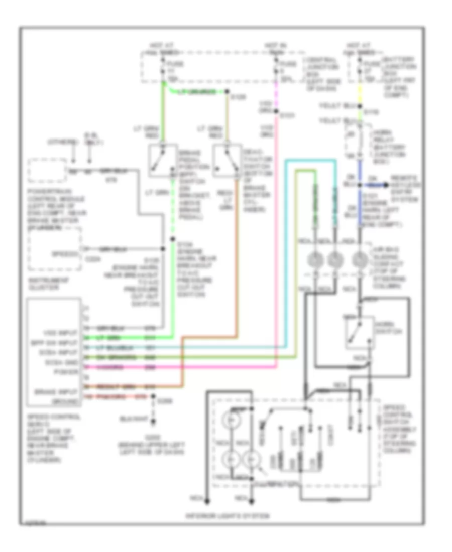
Cruise Control Wiring Diagram for Ford Econoline E250 2000
List of elements for Cruise Control Wiring Diagram for Ford Econoline E250 2000:
- (6.8l only)
- (others)
- Accel set/
- Air bag sliding contact (top of steering column)
- Battery junction box (left frt of eng compt)
- Bpp sw input
- Brake input
- Brake pedal position (bpp) switch (on bracket, above brake pedal)
- C224
- Central junction box (left side of dash)
- Coast
- Deac- tivator switch (bottom of brake master cyl- inder)
- Fuse 10a
- Fuse 15a
- G202 (behind upper left left side of dash)
- Ground
- Horn relay (battery junction box)
- Horn switch
- Hot at all times
- Hot at all times
- Hot in run
- Illumination
- Instrument cluster
- Interior lights system
- Nca
- Off
- Ohms
- Power
- Powertrain control module (left rear of eng compt, near brake master cylinder)
- Remote keyless entry system
- Resume
- S116
- S129
- S131
- S134 (engine harn, near breakout to a/c pressure cut-out switch)
- S135 (engine harn, near breakout to a/c pressure cut-out switch)
- S268
- Scsa gnd
- Scsa input
- Speed control servo (left side of engine compt, near brake master cylinder)
- Speed control switch assembly (top of steering column)
- Speedo
- Vss input
 Čeština
 Dansk
Dansk Deutsch
 Ελληνικά
 English
 English
 Español
 Suomi
Suomi Français
 Français
 עברית
עברית Hrvatski
 Magyar
 Italiano
 日本語
日本語 한국어
한국어 Nederlands
 Polski
 Português
 Português
 Русский
 Slovenčina
 Slovenščina
 Svenska
 Türkçe
 中文 (中国)
 Română