NAVIGATION
Crew Chief Wiring Diagram for Ford F-250 Super Duty King Ranch 2014


List of elements for Crew Chief Wiring Diagram for Ford F-250 Super Duty King Ranch 2014:
- 5vpwr
- 5vtb
- Battery junction box (bjb) (left side of engine compt)
- Body control module (bcm) (right kick panel)
- C2280b
- Cgnd
- Computer data lines system
- Fuse 30a
- Fuse 5a
- G203 (lower left center of dash)
- Gnd
- Gnd1
- Hot at all times
- Hot in start or run
- Hs can+
- Hs can-
- Hsc1-c
- Hsc2-c
- Igrun-c
- Inline fuse (right end of dash)
- Modem-antenna (top center of dash)
- Nca
- Pwr ground
- Red
- Run start
- Rxd
- S272
- S273
- S274
- Telematics module (right end of dash)
- Txd
- Vb1
- Vbatt
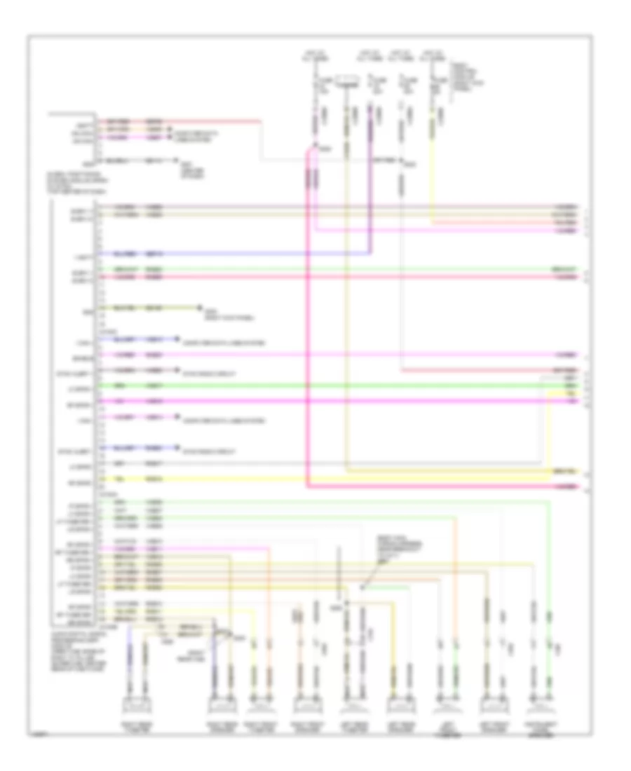
Navigation Wiring Diagram, with Sony (1 of 3) for Ford F-250 Super Duty King Ranch 2014
List of elements for Navigation Wiring Diagram, with Sony (1 of 3) for Ford F-250 Super Duty King Ranch 2014:
- (body main wiring harness, near breakout to c311) s291
- (right rear cab)
- Audio digital signal processing (dsp) module (crew cab: base of right "c" pillar) (super cab: center rear of cab floor)
- Body control module (right kick panel)
- C207
- C2280a
- C2280b
- C2280d
- C3154a
- C3154b
- C3154c
- C555
- C655
- C755
- C855
- Cls32
- Computer data lines system
- Enable
- Fuse 15a
- Fuse 20a
- Fuse 5a
- G201 (center of dash)
- G302 (right kick panel)
- Gd114
- Gd139
- Global positioning system module (gpsm) (w/ sync) (top center of dash)
- Gnd
- Hazard
- Hot at all times
- I can +
- I can -
- Instrument panel speaker
- Ip spkr +
- Ip spkr -
- Left front speaker
- Left front tweeter
- Left rear speaker
- Left rear tweeter
- Lf spkr +
- Lf spkr -
- Lf tweeter +
- Lf tweeter -
- Lr spkr +
- Lr spkr -
- Ms can+
- Ms can-
- Nca
- Rf spkr +
- Rf spkr -
- Rf tweeter +
- Rf tweeter -
- Right front speaker
- Right front tweeter
- Right rear speaker
- Right rear tweeter
- Rme06
- Rme07
- Rme08
- Rme09
- Rme10
- Rme11
- Rme12
- Rme17
- Rme18
- Rme22
- Rme55
- Rme80
- Rr spkr +
- Rr spkr -
- S222
- S228
- S292
- S300
- S301
- Sbp19
- Sbp29
- Sme23
- Subw 1+
- Subw 1-
- Subw 2+
- Subw 2-
- Sync alert +
- Sync alert -
- Sync radio circuit
- V batt
- Vbatt
- Vdb06
- Vdb07
- Vdb13
- Vdb14
- Vme06
- Vme07
- Vme08
- Vme09
- Vme10
- Vme11
- Vme12
- Vme17
- Vme18
- Vme22
- Vme55
- Vme80
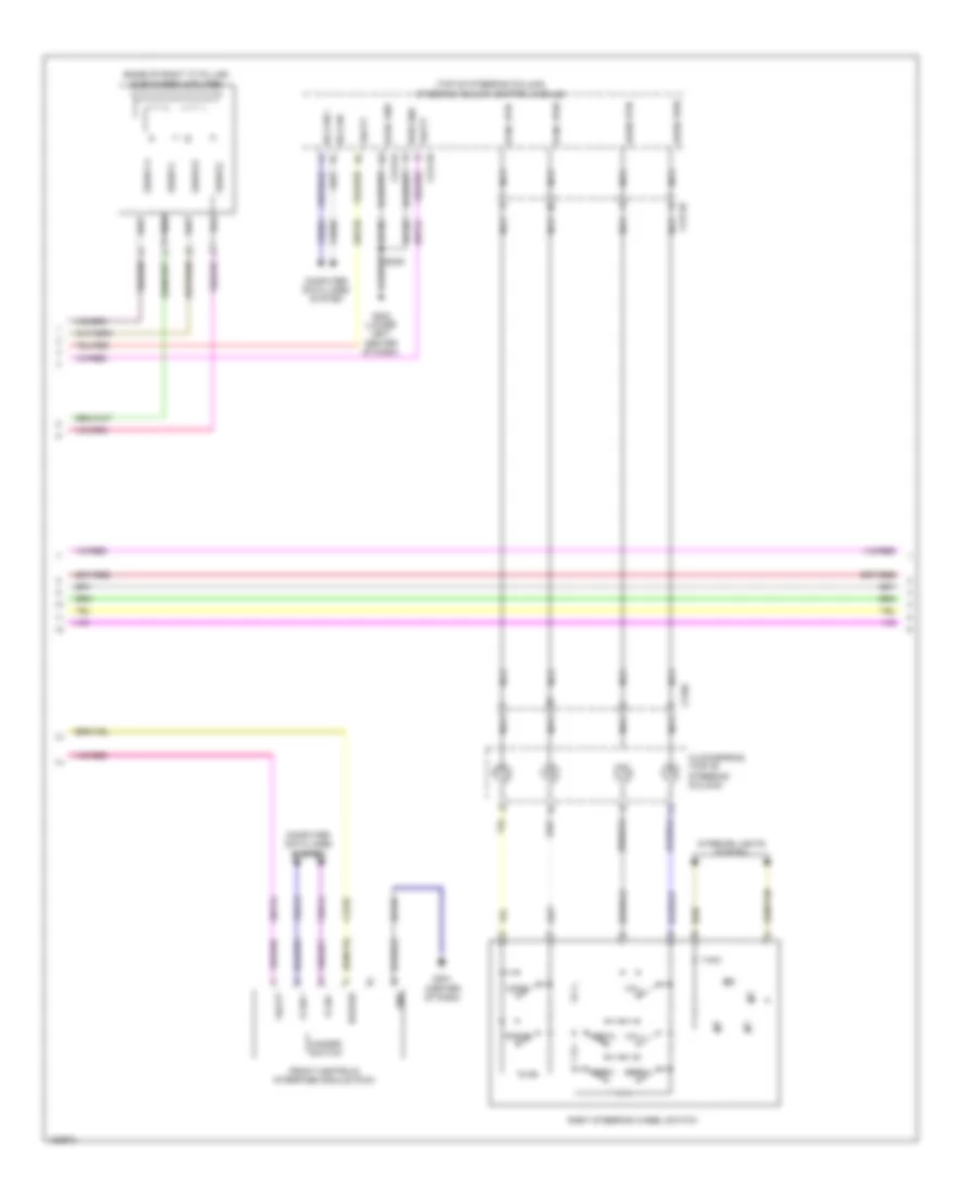
Navigation Wiring Diagram, with Sony (2 of 3) for Ford F-250 Super Duty King Ranch 2014
List of elements for Navigation Wiring Diagram, with Sony (2 of 3) for Ford F-250 Super Duty King Ranch 2014:
- (base of right "c" pillar) subwoofer amplifier
- (top of steering column)
- Audio pwr
- Audio rtn
- C218c
- C2414a
- C2414b
- C2414d
- Clockspring (top of steering column)
- Cls32
- Computer data lines system
- Front controls interface module (fcim)
- G201 (center of dash)
- G202 (lower left center of dash)
- Gd184
- Gd185
- Gnd
- Hazard
- Hazard switch
- Hs can +
- Hs can -
- I can +
- I can -
- Interior lights system
- Logic gnd
- Media
- Nca
- Phone
- Pwr gnd
- Right steering wheel switch
- S239
- Sbp24
- Sbp26
- Seek+
- Seek-
- Steering column control module
- Subw 1+
- Subw 1-
- Subw 2+
- Subw 2-
- Sync pwr
- Sync rtn
- Vbatt
- Vdb04
- Vdb05
- Vdb13
- Vdb14
- Voice
- Vol+
- Vol-
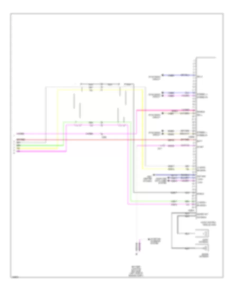
Navigation Wiring Diagram, with Sony (3 of 3) for Ford F-250 Super Duty King Ranch 2014
List of elements for Navigation Wiring Diagram, with Sony (3 of 3) for Ford F-250 Super Duty King Ranch 2014:
- Am/fm antenna
- Amp gnd
- Antenna
- Audio control module (acm)
- Batt
- Battery junction box (bjb) (left side of engine compt)
- C211
- C265
- C290a
- C290b
- Cdc38
- Computer data lines system
- Dme17
- Enable
- G201 (center of dash)
- Gd114
- I can+
- I can-
- Lf spkr +
- Lf spkr -
- Nca
- Rf spkr +
- Rf spkr -
- Rme17
- Rme18
- Rme52
- Rme53
- Sbp29
- Sdars ant
- Sdars antenna
- Sdl-h
- Sdl-l
- Shield
- Sme23
- Start
- Starting/ charging system
- Stereo l+
- Stereo l-
- Stereo r+
- Stereo r-
- Sync radio circuit
- Vdb13
- Vdb14
- Vme17
- Vme18
- Vme52
- Vme53
- Vme90
- Vme91
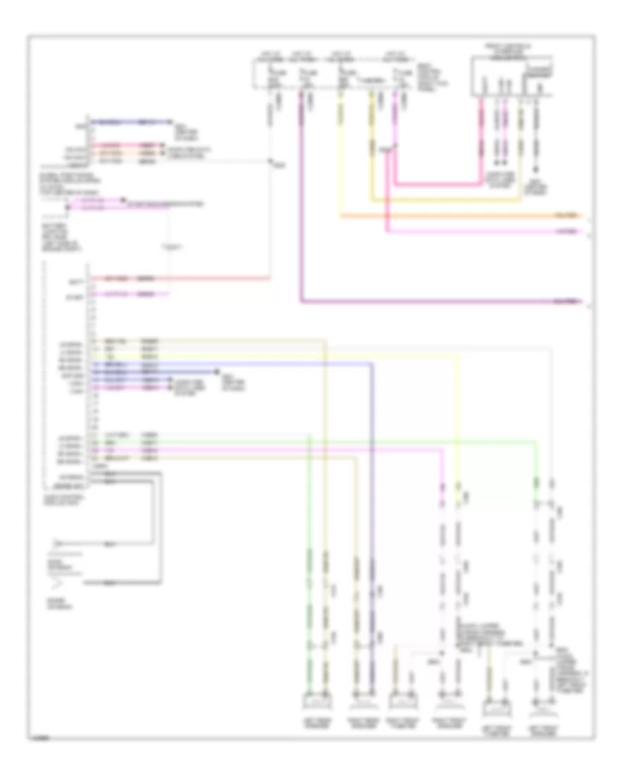
Navigation Wiring Diagram, without Sony (1 of 2) for Ford F-250 Super Duty King Ranch 2014
List of elements for Navigation Wiring Diagram, without Sony (1 of 2) for Ford F-250 Super Duty King Ranch 2014:
- (audio jumper wiring harness, in breakout to right front tweeter) s602
- Am/fm antenna
- Amp gnd
- Antenna
- Audio control module (acm)
- Batt
- Battery junction box (bjb) (left side of engine compt)
- Body control module (right kick panel)
- C211
- C212
- C2280a
- C2280b
- C2280d
- C265
- C290a
- C510
- C555
- C610
- C655
- C756
- C856
- Cdc38
- Cls32
- Computer data lines system
- Front controls interface module (fcim)
- Fuse 15a
- Fuse 20a
- Fuse 5a
- G201 (center of dash)
- Gd114
- Gd184
- Global positioning system module (gpsm) (w/ sync) (top center of dash)
- Gnd
- Hazard
- Hazard switch
- Hot at all times
- I can +
- I can -
- I can+
- I can-
- Left front speaker
- Left front tweeter
- Left rear speaker
- Lf spkr +
- Lf spkr -
- Lr spkr +
- Lr spkr -
- Ms can+
- Ms can-
- Rf spkr +
- Rf spkr -
- Right front speaker
- Right front tweeter
- Right rear speaker
- Rme09
- Rme12
- Rme17
- Rme18
- Rr spkr +
- Rr spkr -
- S222
- S228
- S502 (audio jumper wiring harness, in breakout left front tweeter)
- S503
- S603
- Sbp24
- Sbp29
- Sdars ant
- Sdars antenna
- Start
- Starting/charging system
- Vbatt
- Vdb06
- Vdb07
- Vdb13
- Vdb14
- Vme09
- Vme12
- Vme17
- Vme18
Navigation Wiring Diagram, without Sony (2 of 2) for Ford F-250 Super Duty King Ranch 2014
List of elements for Navigation Wiring Diagram, without Sony (2 of 2) for Ford F-250 Super Duty King Ranch 2014:
- (base of right "c" pillar) subwoofer amplifier
- (crew cab: left "c" pillar) (super cab: left "b" pillar)
- (top of steering column) steering column control module
- Audio control module (acm)
- Audio pwr
- Audio rtn
- Aux aud sh
- C212
- C218b
- C218c
- C2414a
- C2414b
- C2414d
- C265
- C290b
- Clockspring (top of steering column)
- Computer data lines system
- Dme22
- Enable/ clip detect
- G202 (lower left center of dash)
- G301
- Gd185
- Gnd
- Hs can +
- Hs can -
- Interior lights system
- Logic gnd
- Media
- Nca
- Phone
- Pwr gnd
- Right steering wheel switch
- Rme22
- Rme52
- Rme53
- Rme80
- S239
- Sbp24
- Sbp26
- Sdl-l
- Seek+
- Seek-
- Sme23
- Spl-h
- Stereo l+
- Stereo l-
- Stereo r+
- Stereo r-
- Subw +
- Subw -
- Subw - enable/ clip detect
- Sync alert +
- Sync alert -
- Sync pwr
- Sync radio circuit
- Sync rtn
- Vbatt
- Vdb04
- Vdb05
- Vme22
- Vme52
- Vme53
- Vme80
- Vme90
- Vme91
- Voice
- Vol+
- Vol-
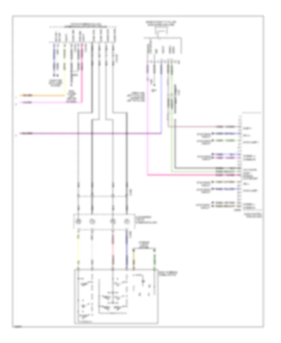
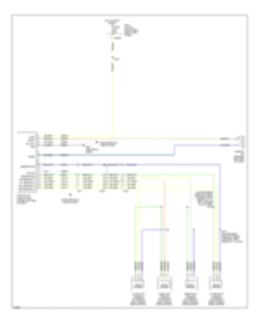
Parking Assistant Wiring Diagram for Ford F-250 Super Duty King Ranch 2014
List of elements for Parking Assistant Wiring Diagram for Ford F-250 Super Duty King Ranch 2014:
- (bumper rear park aid wiring harness, near breakout to left license plate lamp) s415
- (left side of rear bumper)
- Body control module (bcm) (right kick panel)
- C1581
- C211
- C2280b
- C408
- Cbp35
- Cmp09
- Computer data lines system
- Fuse 5a
- G201 (center of dash)
- Gd184
- Gnd
- Hot in start or run
- Hs can+
- Hs can-
- Inner left parking aid sensor
- Inner right parking aid sensor (right side of rear bumper)
- Lmp07
- Outer left parking aid sensor (left side of rear bumper)
- Outer right parking aid sensor (right side of rear bumper)
- Parking aid module (pam) (lower left end of dash)
- Parking aid speaker (left end of dash)
- Ril sensor in
- Rir sensor in
- Rmp07
- Rmp09
- Rol sensor in
- Ror sensor in
- S227
- S416 (bumper rear park aid wiring harness, near breakout to c408)
- Sensor gnd
- Sensor pwr
- Sndr+
- Sndr-
- Solid state
- Vdb04
- Vdb05
- Vmp14
- Vmp15
- Vmp16
- Vmp17
- Vpwr
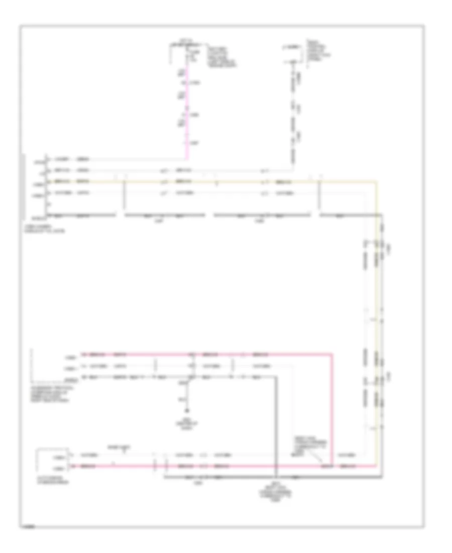
Rear Camera Wiring Diagram for Ford F-250 Super Duty King Ranch 2014
List of elements for Rear Camera Wiring Diagram for Ford F-250 Super Duty King Ranch 2014:
- (body main wiring harness, in breakout to c264) s373
- Accessory protocol interface module (premium audio) (right end of dash)
- Auto dimming interior mirror
- Base audio
- Battery junction box (bjb) (left side of engine compt)
- Body control module (right kick panel)
- C1581
- C210
- C2280c
- C264
- C265
- C465
- C497
- Cbb49
- Dmp19
- Fuse 10a
- G201 (center of dash)
- Hot in start or run
- Lin
- Micro
- Nca
- Rmp19
- S340 (body main wiring harness, in breakout to c265)
- S372
- Shield
- Vdn03
- Video +
- Video -
- Video camera (middle of tail gate)
- Video+
- Video-
- Vmp19
- Vpwr

 Čeština
 Dansk
Dansk Deutsch
 Ελληνικά
 English
 English
 Español
 Suomi
Suomi Français
 Français
 עברית
עברית Hrvatski
 Magyar
 Italiano
 日本語
日本語 한국어
한국어 Nederlands
 Polski
 Português
 Português
 Русский
 Slovenčina
 Slovenščina
 Svenska
 Türkçe
 中文 (中国)