TRANSMISSION
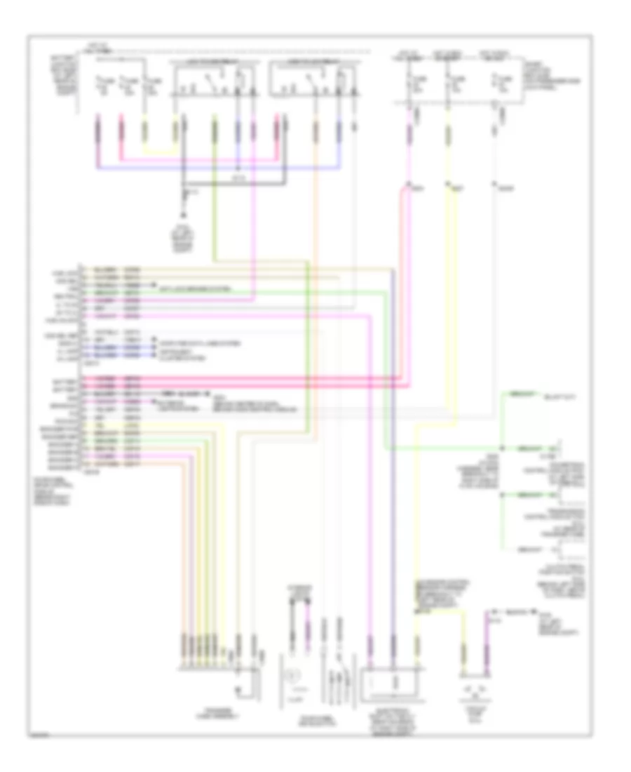
4WD Wiring Diagram for Ford F450 Super Duty 2009
List of elements for 4WD Wiring Diagram for Ford F450 Super Duty 2009:
- (in engine control sensor harness, in breakout to left rear of engine compt) s105
- 2h to 4l
- 4h lamp
- 4l lamp
- 4l to 2h
- 87a
- Anti-lock brakes system
- Battery
- Battery junction box (bjb) (at left rear of engine compt)
- Brake sw
- C175b
- C2280a
- C2280b
- C281a
- C281b
- C350a
- C350b
- Cbp35
- Cbp43
- Ccb08
- Ccf06
- Ccf13
- Ccf14
- Ccf15
- Ccf16
- Ccf17
- Ccf22
- Ccf25
- Ccf26
- Ccf27
- Ccf28
- Cet21
- Clutch pedal position switch (6.4l) (behind left side of dash, above clutch pedal)
- Computer data lines system
- Electronic shift on the fly (esof) solenoid (at right side of engine compt)
- Encoder a
- Encoder b
- Encoder c
- Encoder p
- Encoder pwr
- Encoder ref
- Exterior lights system
- Four-wheel drive control module (behind right side of dash)
- Four-wheel drive switch
- Fuse 10a
- Fuse 20a
- Fuse 30a
- Fuse 5a
- G104 (at left rear of engine compt)
- G108 (at left rear of engine compt)
- G203 (behind center of dash, behind audio control module)
- Gd115
- Gnd
- High to low relay
- Hot at all times
- Hot in run or acc
- Hot in run or start
- Hub lock
- Hub unlock
- Illum
- Instrument cluster system
- Interior lights system
- Iso9141
- Lcf24
- Low to high relay
- Mod sel
- Mod sel ref
- Neutral
- Off
- Powertrain control module (pcm) (at left side of firewall)
- R s
- Rcf09
- Rcf13
- Run/acc
- S115
- S118
- S204
- S208 (in main harness, near breakout to right side of hvac housing)
- S225
- S227
- S2439
- Sbp40
- Smart junction box (sjb) (on passenger side kick panel)
- Transfer case assembly
- Transmission control module (tcm) (6.4l) (at rear of transfer case)
- Vacuum pump (6.4l)
- Vdb10
- Ve822
- Vss
6.4L DIESEL
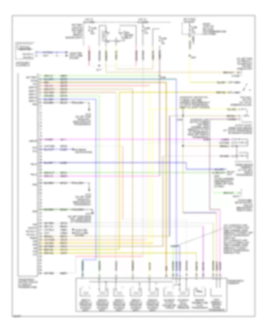
6.4L Diesel, A/T Wiring Diagram for Ford F450 Super Duty 2009
List of elements for 6.4L Diesel, A/T Wiring Diagram for Ford F450 Super Duty 2009:
- (a/t: in backup lamp switch to rear lamp feed harness, near breakout to front left side of transmission, near top) (m/t: in backup lamp switch to rear lamp feed harness, near breakout to right side of transmission, near bottom)
- (at left side of firewall) powertrain control module (pcm)
- (in backup lamp switch to rear lamp feed harness, near breakout to top of transmission, near left side of transmission) s196
- (in backup lamp switch to rear lamp feed harness, near breakout to top of transmission, near tail shaft housing)
- (sspc-a) control a pressure solenoid shift
- (sspc-b) control b pressure solenoid shift
- (sspc-c) control c pressure solenoid shift
- (sspc-d) control d pressure solenoid shift
- (sspc-e) control e pressure solenoid shift
- (tr-p) assembly sensor range transmission
- Battery
- Battery junction box (bjb) (at left rear of engine compt)
- C1232b
- C2280b
- C281a
- Cat15
- Cbb72
- Cet05
- Cet06
- Cet07
- Cet09
- Cet21
- Cet22
- Cet25
- Cet49
- Cet50
- Cls05
- Cls28
- Computer data lines system
- Exterior lights system
- Four-wheel drive control module (behind right side of dash)
- Fuse 10a
- Fuse 15a
- Fuse 50a
- G107 (on left side frame rail, near middle of transmission)
- G116 (on left side frame rail, near middle of transmission)
- Gd120
- Gnd
- Hot at all times
- Hot in run or start
- Hs can (+)
- Hs can (-)
- Instrument cluster (ic)
- Iss
- Le111
- Nca
- Oss
- Output shaft speed (oss) sensor (at top of transmission extension housing)
- Pca
- Pcm power relay
- Re406
- Ret04
- Ret24
- Rlc
- S117
- S192
- S194
- S198
- S208 (in main harness, near breakout under left side of dash)
- S227
- Sbb37
- Sensor temperature fluid transmission
- Sig rtn
- Smart junction box (sjb) (on passenger side kick panel)
- Solenoid (pc-a) control pressure
- Solenoid clutch converter torque
- Speed sensor assembly (at top left side of transmission)
- Sspc a
- Sspc b
- Sspc c
- Sspc d
- Sspc e
- Tcc
- Tcs
- Tft
- Tow haul switch (at top of steering column)
- Tow/haul indicator
- Transmission control module (at rear of transfer case)
- Transmission torqshift
- Trgnd
- Tro n
- Tro p
- Trp
- Tss
- Vbpwr
- Vdb04
- Vdb05
- Ve744
- Vet27
- Vet33
- Vpwr
6.8L
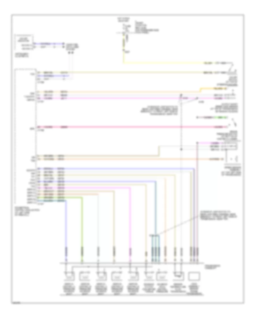
6.8L, A/T Wiring Diagram for Ford F450 Super Duty 2009
List of elements for 6.8L, A/T Wiring Diagram for Ford F450 Super Duty 2009:
- (in backup lamp switch to rear lamp feed harness, near breakout to front left side of transmission, near top)
- (sspc-a) control a pressure solenoid shift
- (sspc-b) control b pressure solenoid shift
- (sspc-c) control c pressure solenoid shift
- (sspc-d) control d pressure solenoid shift
- (sspc-e) control e pressure solenoid shift
- (tr-p) assembly sensor range transmission
- Bps
- Brake pressure switch (at bottom of master cylinder)
- C175b
- C175e
- C175t
- C2280b
- Cat15
- Ces09
- Cet05
- Cet06
- Cet07
- Cet08
- Cet09
- Cet22
- Cet25
- Cet49
- Cet50
- Computer data lines system
- Fuse 10a
- Hot in run or start
- Hs can (+)
- Hs can (-)
- Instrument cluster (ic)
- Iss
- Le111
- Nca
- O/d off indicator
- O/d off switch (at top of steering column)
- Oss
- Output shaft speed (oss) sensor (at top of transmission extension housing)
- Pca
- Powertrain control module (pcm) (at left side of firewall)
- Re406
- Ret04
- Ret24
- S183
- S194
- S196
- S227
- Sensor temperature fluid transmission
- Sig rtn
- Smart junction box (sjb) (on passenger side kick panel)
- Solenoid (pc-a) control pressure
- Solenoid clutch converter torque
- Speed sensor assembly (at top left side of transmission)
- Sspc a
- Sspc b
- Sspc c
- Sspc d
- Sspc e
- T sig rtn
- Tcc
- Tcs
- Tft
- Transmission torqshift
- Trp
- Tss
- Vbpwr
- Ve733
- Ve744
- Vet27
- Vpwr

 Čeština
 Dansk
Dansk Deutsch
 Ελληνικά
 English
 English
 Español
 Suomi
Suomi Français
 Français
 עברית
עברית Hrvatski
 Magyar
 Italiano
 日本語
日本語 한국어
한국어 Nederlands
 Polski
 Português
 Português
 Русский
 Slovenčina
 Slovenščina
 Svenska
 Türkçe
 中文 (中国)