INSTRUMENT CLUSTER
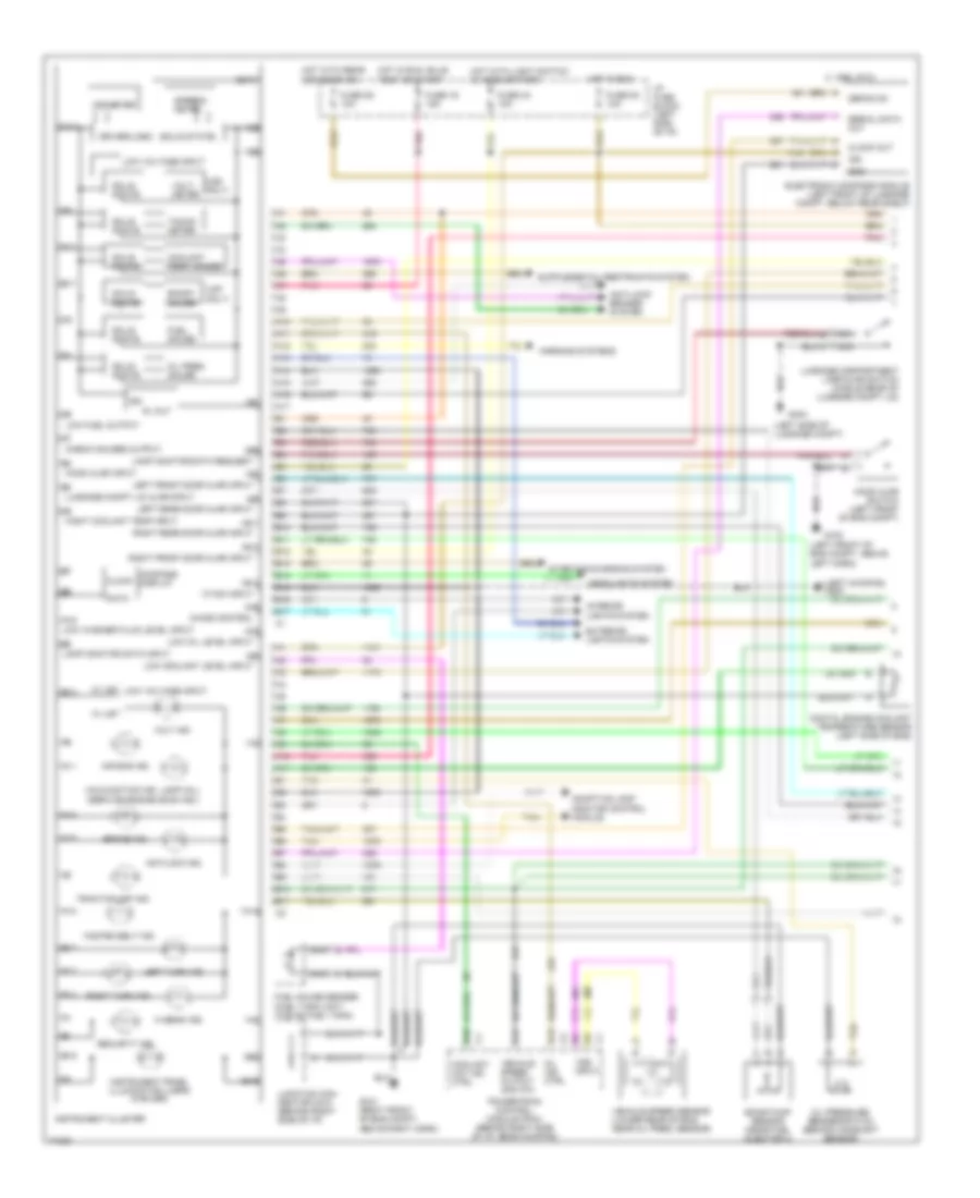
Instrument Cluster Wiring Diagram, Base Cluster, U2E for Pontiac Bonneville SE 1995


List of elements for Instrument Cluster Wiring Diagram, Base Cluster, U2E for Pontiac Bonneville SE 1995:
- (left front of
- A10
- A11
- A12
- A13
- A14
- A15
- A16
- A17
- Accy
- Anti- lock brakes system
- Anti-theft system
- Antilock ind.
- B10
- B11
- B12
- B13
- B14
- B15
- B16
- B17
- Battery input
- Brake fluid level switch (master cylinder reservoir)
- Brake ind.
- Bulb test
- C 1995 vftc
- Check oil ind.
- Computer command ride control module (below left front seat)
- Coolant hot ind. ctrl
- Coolant temp ind.
- Coolant temper- ature gauge
- D15
- Driver logic (solid state)
- Eng compt, above
- Engine controls system
- Exterior lights system
- Fasten belt ind.
- Fuel gauge
- Fuel gauge sender (fuel tank unit) (top of fuel tank)
- Fuse 1d 15a
- Fuse 5a 10a
- Fuse 8 10a
- Fuse 9c 10a
- G100
- G1o1 (right front of eng compt, above right
- G1o1 (right front of eng compt, above right horn)
- G200 (left kickpad)
- Headlights system
- Hi beam ind.
- Hot at all times
- Hot in run
- Hot in run, bulb test or start
- I/p fuse block (left side of i/p)
- Ignition on input
- Ignition on/off timer
- Ignition switch
- Indicator control
- Indicator engine coolant temperature sensor (top left side of eng)
- Infl. rest. ind.
- Instrument cluster
- Instrument panel illumination lamps
- Interior lights system
- Junction con- nector c215 (behind right side of i/p)
- Left horn)
- Left turn ind.
- Lock
- Low
- Low oil level sensor (below starter motor)
- Malfunction ind. lamp (mil) (service engine soon ind.)
- Multi func- tion chime (mfc) module (right of steering column support)
- Nca
- Normal
- Odometer
- Off
- Oil level module (in front of relay center)
- Oil pressure ind.
- Oil pressure switch (behind camshaft sensor)
- Park brake switch (top of park brake assembly)
- Pnk
- Power
- Powertrain control module (pcm) (behind right side of i/p, near kickpad)
- Relay center (right side of i/p, top of shroud)
- Right turn ind.
- Run
- Security ind.
- Signal input
- Signal output
- Speedo- meter
- Start
- Starting/charging system
- Tan
- Vehicle speed output 4000 p/m
- Vehicle speed sensor (lower rear of eng, near oil pres. sensor)
- Volts ind.
- Vss input
- Warning systems
Instrument Cluster Wiring Diagram, Gauges Cluster, U2F & U50 (1 of 2) for Pontiac Bonneville SE 1995
List of elements for Instrument Cluster Wiring Diagram, Gauges Cluster, U2F & U50 (1 of 2) for Pontiac Bonneville SE 1995:
- (left front of eng compt, above left horn)
- (left kickpad) g200
- (left side of luggage compt)
- (solid state)
- (u2f only)
- (u50 only)
- 1a1
- 1a10
- 1a11
- 1a12
- 1a13
- 1a14
- 1a15
- 1a16
- 1a2
- 1a5
- 1a6
- 1a7
- 1b1
- 1b10
- 1b11
- 1b12
- 1b13
- 1b14
- 1b15
- 1b16
- 1b17
- 1b2
- 1b3
- 1b4
- 1b5
- 1b6
- 1b7
- 1b8
- 1b9
- 2a10
- 2a11
- 2a2
- 2a3
- 2a6
- 2a7
- 2a8
- 2a9
- 2b1
- 2b10
- 2b11
- 2b2
- 2b3
- 2b5
- 2b6
- 2b7
- 2b8
- 2b9
- 5v out
- A10
- A11
- A12
- A13
- A14
- A15
- A16
- A17
- Adaptive lamp monitor control module
- Air bag ind.
- Anti-lock brakes system
- Antilock ind.
- B10
- B11
- B12
- B13
- B14
- B15
- B16
- B17
- Boost gauge
- Boost/map sensor (near fuel injector 4)
- Brake ind.
- C 1995 vftc
- Check gauges output
- Chime control
- Clock
- Clock out
- Compass display
- Coolant hot ind. ctrl
- Coolant temp. gauge
- D13
- D15
- Data
- Defog on
- Digital engine coolant temperature sensor (left side of eng)
- Driver/logic
- Electronic compass module (left front of luggage compt, below rear shelf)
- Exterior lights system
- Fasten belt ind.
- Fuel gauge
- Fuel gauge sender (fuel tank unit) (top of fuel tank)
- Fuse 1d 15a
- Fuse 3d 10a
- Fuse 4a 10a
- Fuse 5a 10a
- G100
- G1o1 (right front of eng compt, above right horn)
- G404
- Gnd
- Headlights system
- Hi beam ind.
- Hight coolant temp input
- Hood ajar input
- Hood ajar switch (left front of eng compt)
- Hot in run
- Hot in run, bulb test or start
- Hot with light switch in head or park
- Hot with rear defogger on
- I/p fuse block (left side of i/p)
- Ign
- Instrument cluster
- Instrument panel illumination lamps (8 bulbs)
- Interior lights system
- Junction con- nector c215 (behind right side of i/p)
- Lamp monitor data input
- Lamp monitor data request
- Left front door ajar input
- Left rear door ajar input
- Left turn ind.
- Low coolant level input
- Low fuel output
- Low oil level input
- Low voltage input
- Low washer fluid level input
- Luggage compartment lamp/ajar switch (middle rear of luggage compt lid)
- Luggage compt lid ajar input
- Malfunction ind. lamp (mil) (service engine soon ind.)
- Mil ind. ctrl
- Nca
- Odometer
- Oil pres. gauge
- Oil pressure sender/switch (behind camshaft sensor)
- Pnk
- Powertrain control module (pcm) (behind right side of i/p, near kickpad)
- Right front door ajar input
- Right rear door ajar input
- Right turn ind.
- Security ind.
- Serial data out
- Solid state
- Speedo- meter
- Tacho- meter
- Tan
- Traction off ind.
- Vehicle speed output 4000 p/m
- Vehicle speed sensor (lower rear of eng, near oil pres. sensor)
- Vf dim input
- Volt ind.
- Volt- meter
- Vss input
- W/ u2f
- W/ u50 low voltage input
- Warning systems
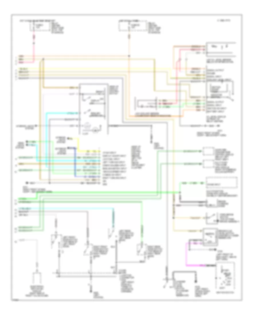
Instrument Cluster Wiring Diagram, Gauges Cluster, U2F & U50 (2 of 2) for Pontiac Bonneville SE 1995
List of elements for Instrument Cluster Wiring Diagram, Gauges Cluster, U2F & U50 (2 of 2) for Pontiac Bonneville SE 1995:
- (c-car) (h-car)
- (left front of
- (right front of eng compt, above right horn)
- Accy
- Battery input
- Brake fluid level switch (master cylinder reservoir)
- Brake warning diode
- Bright
- Bulb test
- C 1995 vftc
- C b
- Check gauges input
- Chime input
- Computer command ride control module (below left front seat)
- Coolant level input
- Dim
- Display on
- Display on/off input
- Electronic ignition (ei) module (right eng of front valve cover)
- Eng compt, above
- English/ metric sw
- English/metric input
- Exterior lights system
- Fuse 8 10a
- Fuse 9c 10a
- G e
- G100
- G100 (left front of eng compt. above left horn)
- G101
- G101 (right front of eng compt, above right horn)
- G200 (left kickpad)
- Gnd
- Head up display control module (behind left top of i/p, above instrument cluster)
- Head up display control switch
- Head- lights system
- Hi beam on input
- Hot at all times
- Hot in run, bulb test or start
- Ign
- Ignition on input
- Ignition on/off timer
- Ignition switch
- Illum
- Indicator control
- Interior lights system
- J f
- Junction connector c340 (left front door sill, taped to composite harness)
- Left front door switch (top rear of left front door)
- Left horn)
- Left rear door switch (top rear of left rear door) c1
- Left turn sig input
- Lock
- Low
- Low coolant sensor (lower right rear of radiator)
- Low fuel input
- Low oil level sensor (below starter motor)
- Multi func- tion chime (mfc) module (right of steering column support)
- Multi-function chime (mfc) module (on relay center bracket)
- Nca
- Normal
- Off
- Oil level module (in front of relay center)
- Park brake switch (top of park brake assembly)
- Pnk
- Power
- Relay center (right side of i/p, top of shroud)
- Right front door switch (top rear of right front door) c1
- Right rear door switch (top rear of right rear door) c1
- Right turn sig input
- Run
- Signal input
- Signal output
- Start
- Vehicle speed input
- Vf dim input
- Washer fluid level switch (in washer fluid reservoir)
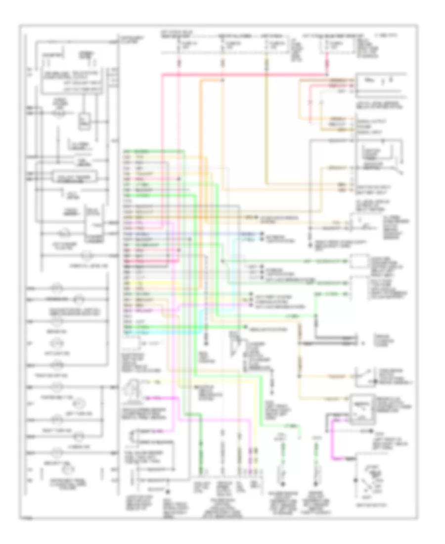
Instrument Cluster Wiring Diagram, Gauges Cluster, UB3 for Pontiac Bonneville SE 1995
List of elements for Instrument Cluster Wiring Diagram, Gauges Cluster, UB3 for Pontiac Bonneville SE 1995:
- (left front of
- (right front of eng compt, above right horn) g101
- (solid state)
- 5v reg.
- A10
- A11
- A12
- A13
- A14
- A15
- A16
- A17
- Accy
- Air bag ind.
- Anti-lock brakes system
- Anti-theft system
- Antilock ind.
- B10
- B11
- B12
- B13
- B14
- B15
- B16
- B17
- Battery input
- Brake fluid level switch (master cylinder reservoir)
- Brake ind.
- Brake warning diode
- Bulb test
- C 1995 vftc
- Check gauges ind.
- Check oil level ind.
- Computer command ride control module (below left front seat)
- Coolant hot ind. ctrl
- Coolant temper- ature gauge
- D13
- D15
- Driver/logic chime control output
- Electronic ignition (ei) module (right end of front valve cover)
- Eng compt, above
- Engine coolant temperature (ect) sensor (behind throttle body)
- Exterior lights system
- Fasten belt ind.
- Fuel gauge
- Fuel gauge sender (fuel tank unit) (top of fuel tank)
- Fuse 1d 15a
- Fuse 5a 10a
- Fuse 8 10a
- Fuse 9c 10a
- G100
- G100 (left front of eng compt. above left horn)
- G1o1 (right front of eng compt, above right horn)
- G202 (left kickpad)
- Gauges engine coolant temperature (ect) sensor (top left side of engine)
- Headlights system
- Hi beam ind.
- Hot at all times
- Hot coolant input
- Hot in run
- Hot in run, bulb test or start
- I/p fuse block (left side of i/p)
- Ignition on input
- Ignition on/off timer
- Ignition switch
- Indicator control
- Instrument cluster
- Instrument panel illumination lamps (8 bulbs)
- Interior lights system
- Junction con- nector c215 (behind right side of i/p)
- Left horn)
- Left turn ind.
- Lock
- Low
- Low oil level sensor (below starter motor)
- Low voltage input
- Low washer fluid ind.
- Malfunction ind. lamp (mil) (service engine soon ind.)
- Mil ind. ctrl
- Multi func- tion chime (mfc) module (right of steering column support)
- Nca
- Normal
- Odometer
- Off
- Oil level module (in front of relay center)
- Oil pres- sure sensor/ switch (behind camshaft sensor)
- Oil pres. gauge
- Park brake switch (top of park brake assembly)
- Pnk
- Power
- Powertrain control module (pcm) (behind right side of i/p, near kickpad)
- Relay center (right side of i/p, top of shroud)
- Right turn ind.
- Run
- Security ind.
- Signal input
- Signal output
- Solid state
- Speedo- meter
- Start
- Starting/charging system
- Tach
- Tacho- meter
- Tan
- Traction off ind.
- Vehicle speed output 4000 p/m
- Vehicle speed sensor (lower rear of eng, near oil pres. sensor)
- Vin k
- Vin l & vin 1
- Volt- meter
- Vss input
- Warning system
- Washer fld sw
- Washer fluid level switch (in washer fluid reservoir)

 Čeština
 Dansk
Dansk Deutsch
 Ελληνικά
 English
 English
 Español
 Suomi
Suomi Français
 Français
 עברית
עברית Hrvatski
 Magyar
 Italiano
 日本語
日本語 한국어
한국어 Nederlands
 Polski
 Português
 Português
 Русский
 Slovenčina
 Slovenščina
 Svenska
 Türkçe
 中文 (中国)