COOLING FAN
Cooling Fan Wiring Diagram for Saturn Ion 3 2004
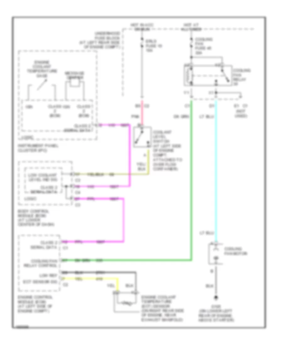
List of elements for Cooling Fan Wiring Diagram for Saturn Ion 3 2004:
- (not used)
- B6 c2
- Body control module (bcm) (at lower center of dash)
- Class (bcm)
- Class 2 serial data
- Coolant level switch (at left side of engine compt, attached to over flow container)
- Cooling fan fuse 45 30a
- Cooling fan motor
- Cooling fan relay
- Cooling fan relay control
- E1 c1
- Ect sensor sig
- Engine control module (ecm) (at left side of engine compt)
- Engine coolant temperature (ect) sensor (on right rear side of engine, near exhaust manifold)
- Engine coolant temperature gage
- Erls fuse 10 10a
- G105 (on lower left rear of engine, above starter)
- Hot at all times
- Hot in acc or run
- Ign
- Instrument panel cluster (ipc)
- Logic
- Low coolant level ind sig
- Low ref
- Message center
- Pnk
- Underhood fuse block (at left rear side of engne compt)
 Čeština
 Dansk
Dansk Deutsch
 Ελληνικά
 English
 English
 Español
 Suomi
Suomi Français
 Français
 עברית
עברית Hrvatski
 Magyar
 Italiano
 日本語
日本語 한국어
한국어 Nederlands
 Polski
 Português
 Português
 Русский
 Slovenčina
 Slovenščina
 Svenska
 Türkçe
 中文 (中国)
 Română