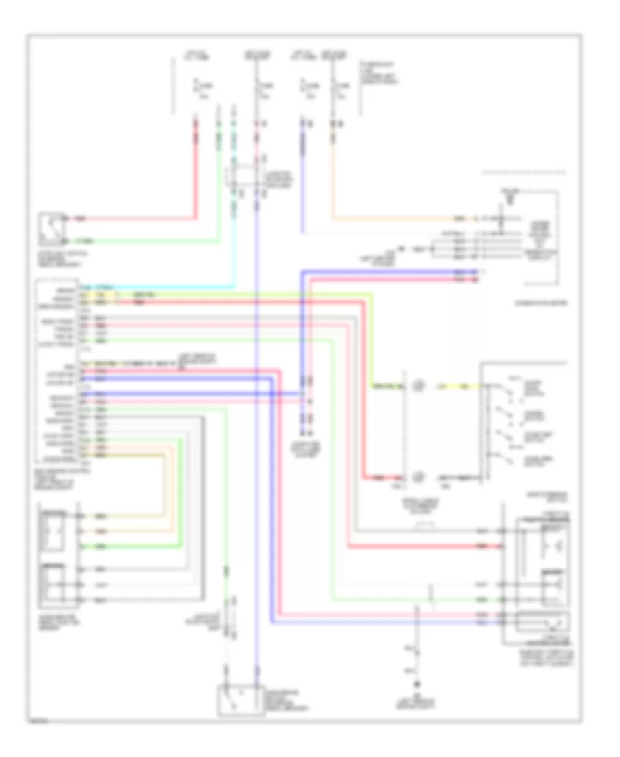
CRUISE CONTROL
Cruise Control Wiring Diagram for Nissan Maxima SV 2009
List of elements for Cruise Control Wiring Diagram for Nissan Maxima SV 2009:
- (left rear of engine compt) e9
- 12m
- Accel/res switch
- Accelerator pedal position sensor
- Aps1
- Aps2
- Ascd brake switch (on brake pedal bracket)
- Ascd steering switch
- Ascdsw
- Avcc1-aps1
- Avcc1-tps-b1
- Avcc2-aps2
- Bncsw
- Brake
- Cancel switch
- Coast/set switch
- Combination meter
- Computer data lines system
- Cruise ind
- E10
- E44
- E45
- E46
- E9 (left rear of engine compt)
- Ecm (engine control module) (left front of engine compt)
- Electric throttle control actuator (on throttle body)
- F13
- F14
- Fuse 10a
- Fuse block (j/b) (lower left side of dash)
- Gnd
- Gnda-aps1
- Gnda-aps2
- Gnda-ascdsw
- Gnda-tps-b1
- Hot at all times
- Hot in on or start
- Junction block e44, e45 & e46
- Junction block e45 & e46
- M30
- M79 (left center of dash)
- M88
- Motor1-b1
- Motor1-b2
- On/off (main) switch
- Pnk
- Red
- Sensor 1
- Sensor 2
- Spiral cable (in steering column)
- Stoplight switch (on brake pedal bracket)
- Throttle control motor
- Throttle position sensor
- Tps1-b1
- Tps2-b1
- Unified meter control unit (w/ information display)
- Vehcan-h
- Vehcan-l
 Čeština
 Dansk
Dansk Deutsch
 Ελληνικά
 English
 English
 Español
 Suomi
Suomi Français
 Français
 עברית
עברית Hrvatski
 Magyar
 Italiano
 日本語
日本語 한국어
한국어 Nederlands
 Polski
 Português
 Português
 Русский
 Slovenčina
 Slovenščina
 Svenska
 Türkçe
 中文 (中国)
 Română