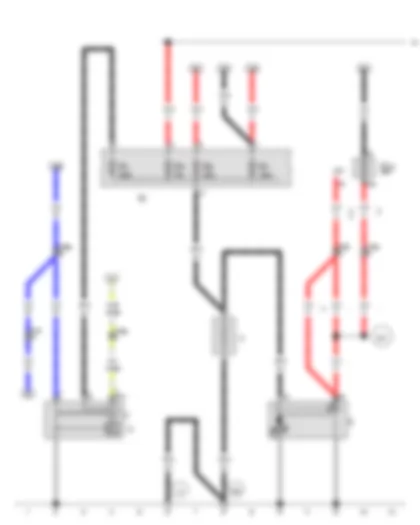
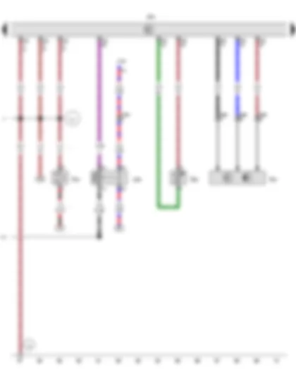
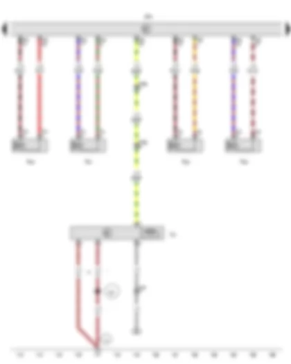
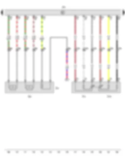
| A | Battery |
| B | Starter |
| C | Alternator |
| C1 | Voltage regulator |
| J207 | Starter inhibitor relay, in E-box in engine compartment |
| SA | Fuse holder A, in E-box in engine compartment |
| SA1 | Fuse 1 in fuse holder A |
| SA4 | Fuse 4 in fuse holder A |
| SA6 | Fuse 6 in fuse holder A |
| SA7 | Fuse 7 in fuse holder A |
| SC23 | Fuse 23 on fuse holder C |
| T10a | 10-pin connector, brown, in E-box in engine compartment |
| T10g | 10-pin connector, grey, in E-box in engine compartment |
| T10l | 10-pin connector, light green, in E-box in engine compartment |
| 14 | Earth point, on gearbox |
| 624 | Earth point, starter battery |
| D50 | Positive connection (30), in engine compartment wiring harness |
| D97 | Connection (50), in engine compartment right wiring harness |
| * | Only models with manual gearbox |
| *2 | Only models with no electric interface |
| *3 | Only models with dual clutch gearbox (DSG) |
| *4 | Only models with electric interface for external use |
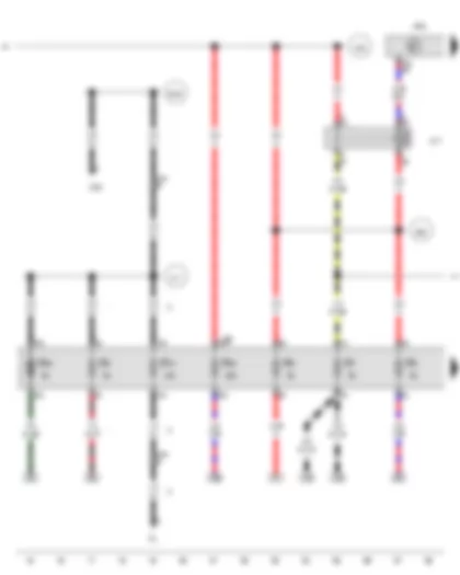
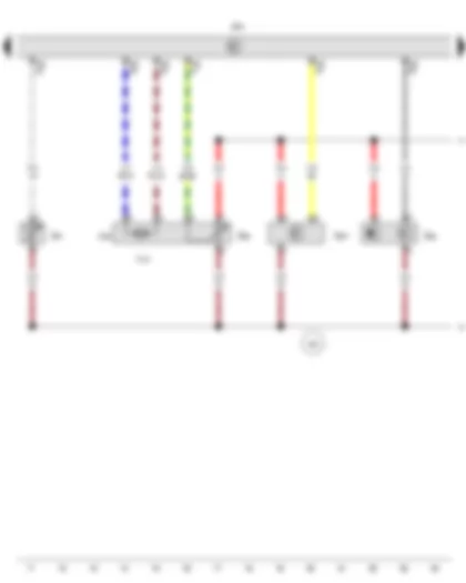
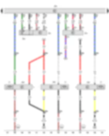
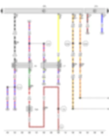
| F4 | Reversing light switch |
| J317 | Terminal 30 voltage supply relay, in E-box in engine compartment |
| J329 | Terminal 15 voltage supply relay |
| J623 | Engine control unit, in E-box in engine compartment |
| SB | Fuse holder B, in E-box in engine compartment |
| SB1 | Fuse 1 on fuse holder B |
| SB2 | Fuse 2 on fuse holder B |
| SB3 | Fuse 3 on fuse holder B |
| SB9 | Fuse 9 on fuse holder B |
| SB15 | Fuse 15 on fuse holder B |
| SB20 | Fuse 20 on fuse holder B |
| SB30 | Fuse 30 on fuse holder B |
| T10 | 10-pin connector, black, in E-box in engine compartment |
| T10l | 10-pin connector, light green, in E-box in engine compartment |
| T94 | 94-pin connector, black |
| B165 | Positive connection 2 (15), in interior wiring harness |
| D17 | Positive connection 1 (15), in engine harness |
| D50 | Positive connection (30), in engine compartment wiring harness |
| D101 | Connection 1 in engine compartment wiring harness |
| E92 | Positive connection 3 (30), in engine compartment wiring harness |
| * | Only models with crankcase breather heater element |
| *2 | Only models with manual gearbox |
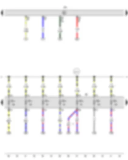
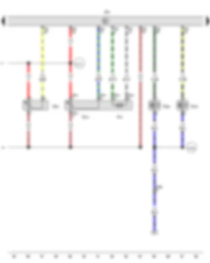
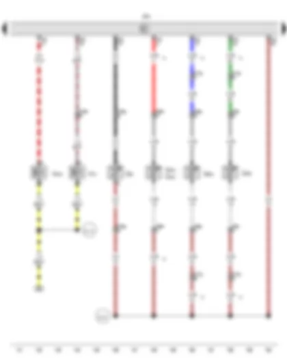
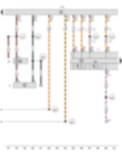
| J179 | Automatic glow period control unit, in E-box in engine compartment |
| J623 | Engine control unit, in E-box in engine compartment |
| Q10 | Glow plug 1 |
| Q11 | Glow plug 2 |
| Q12 | Glow plug 3 |
| Q13 | Glow plug 4 |
| SB | Fuse holder B, in E-box in engine compartment |
| SB32 | Fuse 32 on fuse holder B |
| SB33 | Fuse 33 on fuse holder B |
| T10e | 10-pin connector, white, in E-box in engine compartment |
| T11 | 11-pin connector, black |
| T94 | 94-pin connector, black |
| 131 | Earth connection 2, in engine compartment wiring harness |
| D101 | Connection 1 in engine compartment wiring harness |
| D113 | Connection 11 in engine compartment wiring harness |
| D144 | Positive connection 5 (30), in engine compartment wiring harness |
| D180 | Connection (87a), in engine compartment wiring harness |
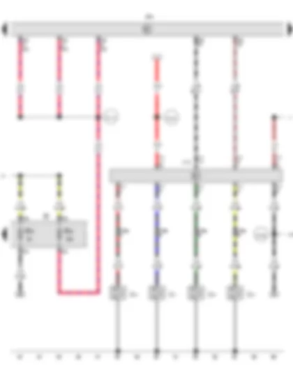
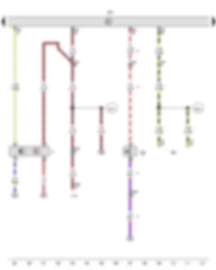
| G40 | Hall sender |
| G62 | Coolant temperature sender |
| J496 | Additional coolant pump relay, in E-box in engine compartment |
| J623 | Engine control unit, in E-box in engine compartment |
| J708 | Residual heat relay |
| N79 | Heater element for crankcase breather |
| T3bf | 3-pin connector, black, near alternator |
| T10h | 10-pin connector, orange, in E-box in engine compartment |
| T60 | 60-pin connector, black |
| T94 | 94-pin connector, black |
| 12 | Earth point, on left in engine compartment |
| 131 | Earth connection 2, in engine compartment wiring harness |
| D180 | Connection (87a), in engine compartment wiring harness |
| * | Only models with crankcase breather heater element |
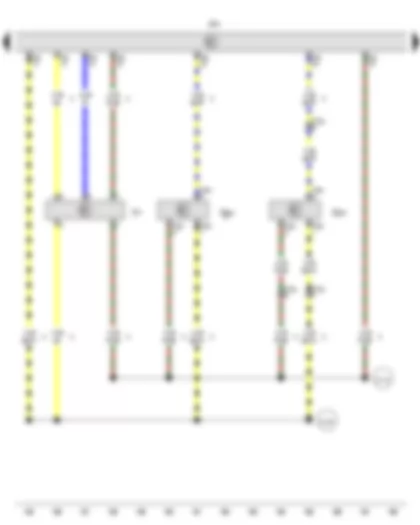
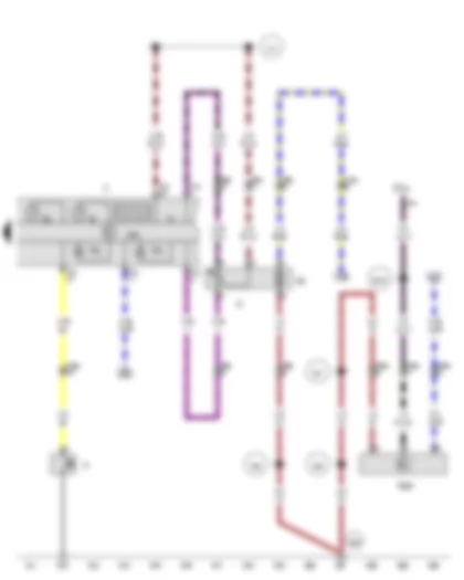
| G212 | Exhaust gas recirculation potentiometer |
| G581 | Position sender for charge pressure positioner |
| J623 | Engine control unit, in E-box in engine compartment |
| N18 | Exhaust gas recirculation valve |
| N276 | Fuel pressure regulating valve |
| N290 | Fuel metering valve |
| T6bw | 6-pin connector, grey |
| T10e | 10-pin connector, white, in E-box in engine compartment |
| T60 | 60-pin connector, black |
| 283 | Earth point 2, engine prewiring harness |
| D141 | Connection (5V) in engine prewiring harness |
| D189 | Connection (87a) in engine prewiring harness |
| E45 | Cruise control system switch |
| F | Brake light switch, on brake master cylinder |
| F36 | Clutch pedal switch |
| J104 | ABS control unit |
| J623 | Engine control unit, in E-box in engine compartment |
| T10 | 10-pin connector, black, in E-box in engine compartment |
| T10f | 10-pin connector, green, in E-box in engine compartment |
| T10h | 10-pin connector, orange, in E-box in engine compartment |
| T38a | 38-pin connector, brown |
| T41 | 41-pin connector, grey |
| T94 | 94-pin connector, black |
| B131 | Connection (54), in interior wiring harness |
| B441 | Connection (CCS), in main wiring harness |
| * | Only models with cruise control system (CCS) |
| *2 | Only models with manual gearbox |
| J623 | Engine control unit, in E-box in engine compartment |
| N30 | Injector, cylinder 1 |
| N31 | Injector, cylinder 2 |
| N32 | Injector, cylinder 3 |
| N33 | Injector, cylinder 4 |
| T2h | 2-pin connector, black |
| T2i | 2-pin connector, black |
| T2j | 2-pin connector, black |
| T2k | 2-pin connector, black |
| T10e | 10-pin connector, white, in E-box in engine compartment |
| T10g | 10-pin connector, grey, in E-box in engine compartment |
| T10l | 10-pin connector, light green, in E-box in engine compartment |
| T60 | 60-pin connector, black |
| V51 | Continued coolant circulation pump |
| 12 | Earth point, on left in engine compartment |
| 281 | Earth point 1, engine prewiring harness |
| * | Only models with dual clutch gearbox (DSG) |
| *2 | Only models with manual gearbox |
| G31 | Charge pressure sender |
| G42 | Intake air temperature sender |
| G70 | Air mass meter |
| J293 | Radiator fan control unit |
| J623 | Engine control unit, in E-box in engine compartment |
| T4a | 4-pin connector, black |
| T4ak | 4-pin connector, black, near radiator fan |
| T4ax | 4-pin connector, black, near radiator fan |
| T4bu | 4-pin connector, black |
| T94 | 94-pin connector, black |
| V7 | Radiator fan |
| 642 | Earth point for electronically controlled fan |
| * | Only models with medium fan output |
| *2 | Only models with increased fan output |
| *3 | Only models with low fan output |
| G83 | Radiator outlet coolant temperature sender |
| G235 | Exhaust gas temperature sender 1 |
| G448 | Exhaust gas temperature sender 2 |
| G495 | Exhaust gas temperature sender 3 |
| G648 | Exhaust gas temperature sender 4 |
| J623 | Engine control unit, in E-box in engine compartment |
| N75 | Charge pressure control solenoid valve |
| N345 | Exhaust gas recirculation cooler changeover valve |
| T2ah | 2-pin connector, black, on right in engine compartment |
| T2cq | 2-pin connector, light brown, on underbody, near cross panel |
| T2cr | 2-pin connector, brown, on underbody, near cross panel |
| T10e | 10-pin connector, white, in E-box in engine compartment |
| T10g | 10-pin connector, grey, in E-box in engine compartment |
| T17g | 17-pin connector, black, in E-box in engine compartment |
| T60 | 60-pin connector, black |
| T94 | 94-pin connector, black |
| D114 | Connection 12 in engine compartment wiring harness |
| D121 | Connection 19 in engine compartment wiring harness |
| * | According to equipment |
| *2 | Only models with diesel particulate filter |
| G71 | Intake manifold pressure sender |
| G450 | Exhaust gas pressure sensor 1 |
| J623 | Engine control unit, in E-box in engine compartment |
| T3az | 3-pin connector, black |
| T17g | 17-pin connector, black, in E-box in engine compartment |
| T94 | 94-pin connector, black |
| D119 | Connection 17 in engine compartment wiring harness |
| D120 | Connection 18 in engine compartment wiring harness |
| * | Only models with all-wheel drive |
| *2 | Only models with no all-wheel drive |
| *3 | Only models with diesel particulate filter |
| *4 | Only models with no diesel particulate filter or with no preparation for diesel particulate filter |
| J17 | Fuel pump relay, in E-box in engine compartment |
| J49 | Electric fuel pump 2 relay, in E-box in engine compartment |
| J519 | Onboard supply control unit |
| J623 | Engine control unit, in E-box in engine compartment |
| T2dp | 2-pin connector, black, near fuel filter |
| T10d | 10-pin connector, blue, in E-box in engine compartment |
| T10e | 10-pin connector, white, in E-box in engine compartment |
| T60 | 60-pin connector, black |
| T73a | 73-pin connector, black |
| T73b | 73-pin connector, white |
| T94 | 94-pin connector, black |
| V393 | Supplementary fuel pump |
| 12 | Earth point, on left in engine compartment |
| 132 | Earth connection 3, in engine compartment wiring harness |
| B383 | Connection 1 (powertrain CAN bus, high), in main wiring harness |
| B390 | Connection 1 (powertrain CAN bus, low), in main wiring harness |
| D78 | Positive connection 1 (30a), in engine compartment wiring harness |
| D110 | Connection 8 in engine compartment wiring harness |
| D159 | Connection (high bus), in engine compartment wiring harness |
| D160 | Connection (low bus), in engine compartment wiring harness |
| D | Ignition/starter switch |
| J59 | X-contact relief relay |
| J285 | Control unit in dash panel insert |
| J519 | Onboard supply control unit |
| K | Dash panel insert |
| K2 | Alternator warning lamp |
| K3 | Oil pressure warning lamp |
| SC21 | Fuse 21 on fuse holder C |
| T10a | 10-pin connector, brown, in E-box in engine compartment |
| T32 | 32-pin connector, blue |
| T73b | 73-pin connector, white |
| B173 | Positive connection 2 (X), in interior wiring harness |
| B239 | Positive connection 1 (50), in interior wiring harness |
| B240 | Positive connection 2 (50), in interior wiring harness |
| B383 | Connection 1 (powertrain CAN bus, high), in main wiring harness |
| B390 | Connection 1 (powertrain CAN bus, low), in main wiring harness |
| B464 | Connection (speed signal), in main wiring harness |
| B708 | Connection 1 (dash panel insert CAN bus high) in main wiring harness |
| B709 | Connection 1 (dash panel insert CAN bus low) in main wiring harness |
| * | Only models with no rain and light sensor |
| *2 | Only models with no tachograph |
| *3 | Only models with rain sensor |
| *4 | Only models with tachograph |
| F1 | Oil pressure switch |
| G | Fuel gauge sender |
| G1 | Fuel gauge |
| G5 | Rev. counter |
| G6 | Fuel system pressurisation pump |
| G266 | Oil level and oil temperature sender |
| J285 | Control unit in dash panel insert |
| K | Dash panel insert |
| K29 | Glow period warning lamp |
| K38 | Oil level warning lamp |
| SC30 | Fuse 30 on fuse holder C |
| T3bc | 3-pin connector, black, on underbody, near cross panel |
| T6b | 6-pin connector, black, on fuel tank |
| T10a | 10-pin connector, brown, in E-box in engine compartment |
| T10c | 10-pin connector, yellow, in E-box in engine compartment |
| T32 | 32-pin connector, blue |
| Y4 | Trip counter |
| 366 | Earth connection 1, in main wiring harness |
| 367 | Earth connection 2, in main wiring harness |
| 368 | Earth connection 3, in main wiring harness |
| 410 | Earth connection 1 (sender earth) in main wiring harness |
| 636 | Earth point, onboard supply control unit |
| B278 | Positive connection 2 (15a) in main wiring harness |
| * | Only models with extended servicing intervals (ESI) |
 Deutsch
 English
 English
 Español
 Français
 Nederlands
 Русский

