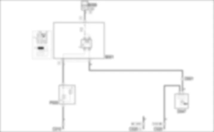

WIRING DIAGRAM - HORNS - Alfa Romeo 159 1.9 JTD 8V Da 01/06
COMPONENTS - HORNS - Alfa Romeo 159 1.9 JTD 8V Da 01/06
| Component code | Description | Reference to the operation |
| B001 | JUNCTION UNIT | |
| B099 | MAXIFUSE BOX ON BATTERY | |
| C010 | LEFT FRONT EARTH | - |
| C020 | PASSENGER SIDE DASHBOARD EARTH | - |
| D001 | FRONT/DASHBOARD COUPLING | - |
| D047 | CLOCK SPRING COUPLING | |
| P005 | SINGLE-TONE HORN |
COMPONENT LOCATION - HORNS - Alfa Romeo 159 1.9 JTD 8V Da 01/06
| Component code | Description | Reference to the operation |
| B001 | JUNCTION UNIT | |
| B099 | MAXIFUSE BOX ON BATTERY | |
| C010 | LEFT FRONT EARTH | - |
| C020 | PASSENGER SIDE DASHBOARD EARTH | - |
| D001 | FRONT/DASHBOARD COUPLING | - |
| D047 | CLOCK SPRING COUPLING | |
| P005 | SINGLE-TONE HORN |
DESCRIPTION - HORNS - Alfa Romeo 159 1.9 JTD 8V Da 01/06
The vehicle is equipped with a horn system consisting of two horns with different tones: one high tone and one low tone: the two horns come on simultaneously.The horns are operated by pressing the sides of the steering wheel cover (around the Air Bag).The horn circuit is protected by a specific fuse and controlled by a relay located in the engine compartment junction unit.For safety reasons, the horns can be operated at any time even with the TEG switched off.
FUNCTIONAL DESCRIPTION - HORNS - Alfa Romeo 159 1.9 JTD 8V Da 01/06
The system for the horns receives a power supply via the horn relay T3 of the engine compartment junction unit B1 from the line directly from the battery via fuse F10 in junction unit B1.The relay coil is energized by an earth signal produced by the closing of one of the switches on the steering wheel, connected via the wiring through the clock spring D47. The relay thereby supplies the horns P05.
 Deutsch
 English
 English
 Español
 Français
 Nederlands
 Русский

