ANTI-LOCK BRAKES
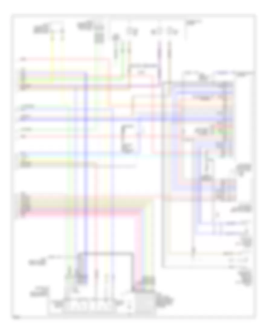
Anti-lock Brake Wiring Diagrams (1 of 2) for Infiniti Q45 1997


List of elements for Anti-lock Brake Wiring Diagrams (1 of 2) for Infiniti Q45 1997:
- (behind right kick panel) throttle motor relay
- (left end of dash) g202
- 16b
- Abs actr mon
- Abs actr rly
- Abs mtr mon
- Abs mtr rly
- Abs w/l
- Abs/tcs control unit (behind right end of dash)
- Ascd (cruise) control unit (behind dash, left of steering column)
- Bus-b
- Computer data lines system
- Consult rx
- Consult tx
- Diag-l
- Dkr
- Dkv
- Eccs tach
- Fuse 28 10a
- Fuse 30 10a
- Fuse 31 7.5a
- Fuse 34 7.5a
- Fuse 37 15a
- Fuse 4 7.5a
- Fuse 56 15a
- Fuse block (behind left side of dash)
- Fuse j 30a
- Fuse k 30a
- Fuse, fusible link and relay box (right front side of engine compt, near battery)
- G203 (right kick panel)
- Grd
- Grd-lan
- Hot at all times
- Hot in on or start
- Hot in start
- Joint connector 1 (behind left side of dash)
- Joint connector 6 (upper right side of dash)
- Left front wheel sensor
- Lft frt in
- Lft frt out
- Lft frt sens
- Lft rr sens
- Nca
- Pnk
- Rear wheel sensor
- Red
- Right front wheel sensor
- Rr in sol
- Rr out sol
- Rt frt in
- Rt frt out
- Rt frt sens
- Rt rr sens
- Slip ind
- Stop lamp switch (brake pedal bracket)
- Stop sw
- Tcs active
- Tcs off ind
- Tcs sw
- Tcs switch
- Transmission control module (left kick panel)
- Vign
Anti-lock Brake Wiring Diagrams (2 of 2) for Infiniti Q45 1997
List of elements for Anti-lock Brake Wiring Diagrams (2 of 2) for Infiniti Q45 1997:
- (front of engine) g125
- Abs actuator (right rear of engine compt, behind strut tower)
- Abs ind
- Abs relay unit (right rear of engine compt)
- Combination meter
- Computer data lines system
- Diode
- Ecm (eccs) control module (right kick panel)
- G100 (front of left front fender)
- G125 (front of engine)
- Joint connector 1 (behind left side of dash)
- Joint connector 8 (behind left kick panel)
- Motor relay
- Nca
- Pnk
- Red
- Secondary throttle position sensor (on throttle body)
- Slip ind
- Solenoid valve relay
- Tac module (behind right kick panel)
- Tach signal input
- Tcs off ind
- Throttle motor (on throttle body)
- Transmissions system

 Čeština
 Dansk
Dansk Deutsch
 Ελληνικά
 English
 English
 Español
 Suomi
Suomi Français
 Français
 עברית
עברית Hrvatski
 Magyar
 Italiano
 日本語
日本語 한국어
한국어 Nederlands
 Polski
 Português
 Português
 Română
 Slovenčina
 Slovenščina
 Svenska
 Türkçe
 中文 (中国)