TRANSMISSION
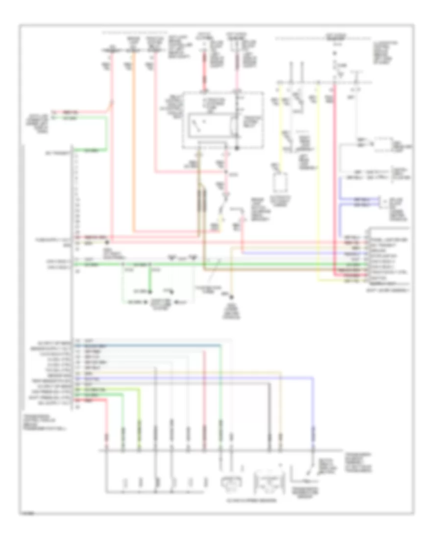
A/T Wiring Diagram for Chrysler Crossfire 2004
List of elements for A/T Wiring Diagram for Chrysler Crossfire 2004:
- 1-2/4-5 sold ctrl
- 13a
- 2-3 sol ctrl
- 3-4 sol ctrl
- Anti-lock brake controller (at left rear of eng compt)
- Ash receiver lamp
- Automatic day/night mirror
- Brake lamp sw output
- Brake lamp switch (on brake pedal bracket)
- Can c bus (+)
- Can c bus (-)
- Computer data lines system
- Data link connector (under left side of dash)
- Fuse 15a
- G203 (under center console)
- G204 (at right kick panel)
- Gnd
- Ground
- Hot at all times
- Hot in run or start
- Ignition
- Illumination control module (behind left side of dash)
- Instru- ment cluster
- Left rear lamp assembly
- Mod press sol ctrl
- N2 and n3 speed sensors
- N2 input sp sens
- N3 input sp sens
- Nca
- Panel lamp driver
- Pnk/ red
- Pnk/red
- Red
- Relay control module (in control module box)
- Right rear lamp assembly
- S103
- S122
- S123
- S124
- S125
- Sci transmit
- Sensor gnd
- Shift lever assembly
- Shift press sol ctrl
- Splice block (left side of engine compt)
- Splice block (under center console)
- Stoplamp sw
- Switch open in park and neutral
- Tcc sol ctrl
- Temp sensor p/n sw
- Traction rly ctrl
- Traction system relay
- Traction system relay output
- Traction systems fuse 15a
- Transmission control module (behind passenger footwell)
- Transmission solenoid assembly (at bottom of transmission)
- Transmission temperature sensor
- Twisted pair wires
 Čeština
 Dansk
Dansk Deutsch
 Ελληνικά
 English
 English
 Español
 Suomi
Suomi Français
 Français
 עברית
עברית Hrvatski
 Magyar
 Italiano
 日本語
日本語 한국어
한국어 Nederlands
 Polski
 Português
 Português
 Română
 Slovenčina
 Slovenščina
 Svenska
 Türkçe
 中文 (中国)
 Русский