СИСТЕМА КРУИЗКОНТРОЛЯ
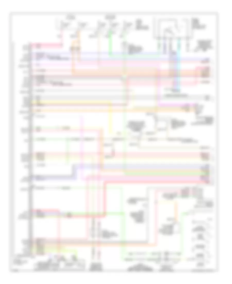
Электросхема системы круизконтроля для Infiniti Q45 2003

Электросхема системы круизконтроля для Infiniti Q45 2003 - Список элементов:
- (spiral cable) combination switch
- 21r
- 24r
- 29r
- 31r
- Actr high side
- Air valve
- Air valve low side
- Ascd
- Ascd brake switch (on bracket, above brake pedal)
- Ascd control unit (behind dash, left of steering column)
- Ascd pump (at right rear corner of engine compt)
- Ascd steering wheel switch
- Brake sw input
- Cancel switch
- Combination meter
- Computer data lines system
- Control sw (a/d) input
- Control sw input (gnd)
- Cruise
- Cruise lamp input
- Data link connector (under left side of dash)
- Dual mode muffler control unit (at right side of trunk)
- E24 (on right front strut tower)
- Ecm prun input
- Engine control module (behind glove box)
- Etc prun
- F101
- F102
- F8 (at left front of engine compt, near engine oil level guage)
- Fuse 12 10a
- Fuse 17 15a
- Fuse 9 10a
- Fuse block (j/b) 1 (behind left end of dash)
- Fuse, fusible link & relay block (j/b) (in engine room box)
- Gnd
- Gnd-c
- Hot at all times
- Hot in on or start
- Ign sw
- Joint connector 12 (behind top center of dash, taped to harness)
- Joint connector 16 (behind upper right end of dash, taped to harness)
- Joint connector 18 (behind upper right end of dash, taped to harness)
- Joint connector 4 (behind upper left side of dash)
- Joint connector 5 (behind left side of dash, taped to harness)
- Joint connector 7 (behind center of dash)
- Joint connector 8 (behind center of dash)
- M114 (behind right side of dash)
- M24 (behind left side of dash)
- M25 (behind left side of dash)
- M41
- M42
- M43
- M441
- M53
- Main switch
- Motor low side
- Od cancel sig
- Park/neutral position relay
- Pnk
- Rel valve low side
- Release valve
- Resume/ accel sw
- Rxi
- Set
- Set lamp output
- Set/ coast switch
- Solenoid monitor input
- Start rly
- Stoplight switch (on bracket above brake pedal)
- Tcs input
- Throttle position input
- Transmission control module (behind glove box)
- Tvo0
- Txi
- Unified meter control unit
- Vacuum motor
- Vdc/tcs/abs control unit (behind right kick panel)
- Vehicle speed input
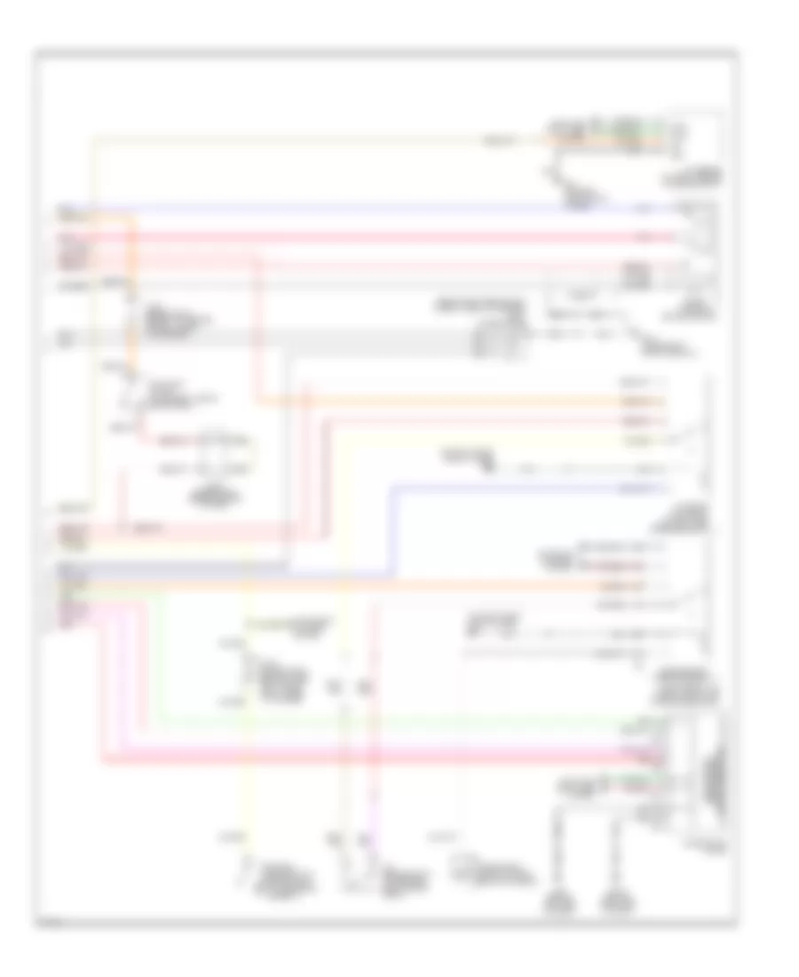
Электросхема интеллектуального круиз контроля (1 из 2) для Infiniti Q45 2003
Электросхема интеллектуального круиз контроля (1 из 2) для Infiniti Q45 2003 - Список элементов:
- (on right front fenderwell, forward of engine room box) e42
- (under left side of dash, near ascd control unit) icc warning chime
- 19b
- Accel/ resume sw
- Air valve
- Ascd pump (at right rear corner of engine compt)
- B243
- B244
- B245
- Bat-1
- Bat-2
- Bnc-sw
- Bno-sw
- Brake pressure sensor (at left rear of engine compartment)
- Buzz
- Can-h
- Can-l
- Cancel switch
- Coast/ set switch
- Combination switch (spiral cable)
- Computer data lines system
- Cruise
- Data link connector (under left side of dash)
- Ddl-rx
- Ddl-tx
- Distance switch
- Dual mode muffler control unit (at right side of trunk)
- E215
- Engine control module (behind glove box)
- Engine controls system
- Front wiper motor (on left side of firewall)
- Fuse 1 10a
- Fuse 17 15a
- Fuse 34 20a
- Fuse 77 10a
- Fuse 9 10a
- Fuse block (j/b) 1 (behind left end of dash)
- Gnd
- Gnd-1
- Gnd-2
- Gnd-3
- Gnd-a
- Gnd-s
- Gnd/sw 1
- Hot at all times
- Hot in on and start
- Icc steering switch
- Icc unit (at right side of trunk)
- Ign-1
- Ign-2
- Instrument cluster system
- Joint connector 12 (behind top center of dash, taped to harness)
- Joint connector 3 (behind upper left side of dash)
- Joint connector 30 (behind right kick panel, taped to harness)
- Joint connector 4 (behind upper left side of dash)
- Joint connector 8 (behind center of dash)
- M441
- M53
- Od cancel
- On/off switch
- Pkb sw
- Pnk
- Psen-gnd
- Psen-pwr
- Psen-sig
- Red
- Release valve
- Rls-nc
- Rls-no
- Rls-pwr
- Safty
- Sig/sw 2
- Sol +
- Sol -
- Stp-lmp
- T-rly
- Tvo
- Tvo0
- Vacuum motor
- Vacuum mtr
- Vent
- Vout
- Vpwr
- Warn
- Wip-h
- Wip-l
- Wiper/washer system
Электросхема интеллектуального круиз контроля (2 из 2) для Infiniti Q45 2003
Электросхема интеллектуального круиз контроля (2 из 2) для Infiniti Q45 2003 - Список элементов:
- (behind right rear shock tower, taped to harness) joint connector 36
- (on right front strut tower) e24
- (with icc indicator)
- 14r
- 15r
- 21r
- 24r
- 29r
- 31r
- B217 (under right front door sill)
- Boost solenoid
- Brake booster
- Can-h
- Can-l
- Combination meter
- Computer data lines system
- Control unit unified meter
- E24 (on right front strut tower)
- F103
- Fuse,fusible link & relay block (j/b) (in engine room box)
- Gnd
- Icc brake hold relay (at right side of engine compt)
- Icc brake switch (on bracket, above brake pedal)
- Icc sensor (at front center of engine compt)
- Ign
- Instrument cluster system
- Joint connector 12 (behind top center of dash, taped to harness)
- Joint connector 17 (behind upper right end of dash, taped to harness)
- Joint connector 7 (behind center of dash)
- M114 (behind right side of dash)
- M24 (behind left side of dash)
- M41
- M42
- M43
- Nca
- Park/neutral position relay
- Parking brake switch (behind dash, at park brake assembly)
- Pnk
- Red
- Start -rly
- Starting/ charging system
- Stoplight switch (on bracket, above brake pedal)
- Transmission control module (behind glove box)