СИСТЕМА АНТИБЛОКИРОВОЧНОЙ ТОРМОЗНОЙ СИСТЕМЫ ABS
Электросхема антиблокировочной тормозной системы АБС (ABS) (1 из 2) для Audi A6 Quattro Premium Plus 2014


Электросхема антиблокировочной тормозной системы АБС (ABS) (1 из 2) для Audi A6 Quattro Premium Plus 2014 - Список элементов:
- 40a
- Abs control module (part of abs hydraulic unit)
- Abs control module fuse 1
- Abs hydraulic pump
- Abs hydraulic unit
- Auto hold button
- Computer data lines system
- Driver central locking lock unit
- Driver door control module (in driver front door)
- Driving dynamics regulation high pressure switch valve 1
- Driving dynamics regulation high pressure switch valve 2
- Driving dynamics regulation switch valve 1
- Driving dynamics regulation switch valve 2
- Electro-mechanical parking brake button
- Fuse 10a
- Fuse 5a
- Fuse carrier
- G55 (near abs control module)
- Hot at all times
- Left front abs inlet valve
- Left front abs outlet valve
- Left front abs wheel speed sensor (on left front wheel hub)
- Left rear abs inlet valve
- Left rear abs outlet valve
- Left rear abs wheel speed sensor (on left rear wheel hub)
- Main fuse carrier (in luggage compt on battery)
- Pnk
- Red
- Relay & fuse panel b (left end of dash)
- Right front abs inlet valve
- Right front abs outlet valve
- Right front abs wheel speed sensor (on right front wheel hub)
- Right rear abs inlet valve
- Right rear abs outlet valve
- Right rear abs wheel speed sensor (on right rear wheel hub)
- Safety fuse 3 150a
- T16c
- T17i
- T23a
- T32a
- Vehicle electrical system control module (left end of dash)
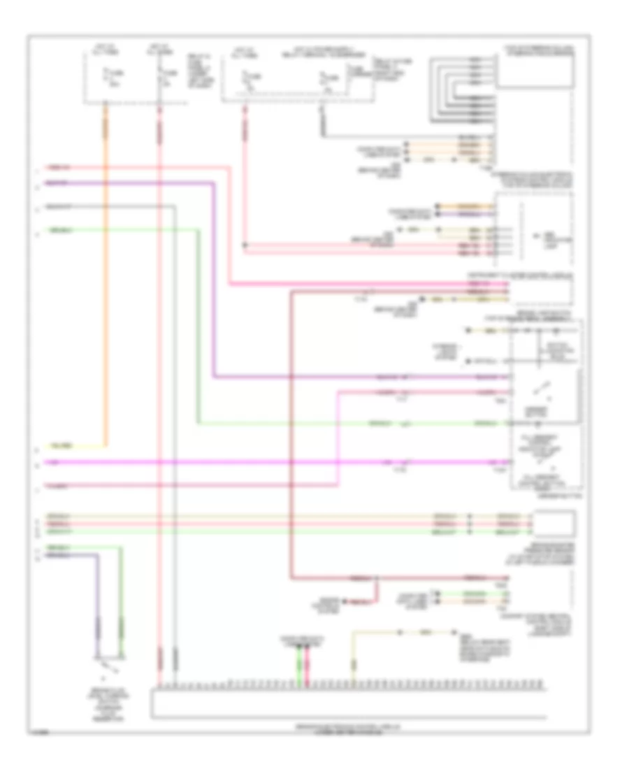
Электросхема антиблокировочной тормозной системы АБС (ABS) (2 из 2) для Audi A6 Quattro Premium Plus 2014
Электросхема антиблокировочной тормозной системы АБС (ABS) (2 из 2) для Audi A6 Quattro Premium Plus 2014 - Список элементов:
- (top of steering column) steering angle sensor
- Abs indicator lamp
- Asr/esp button
- Brake booster pressure sensor (w/ start/stop system) (in left plenum chamber)
- Brake fluid level warning switch (on brake fluid reservoir)
- Brake lamp switch (top of brake pedal assembly)
- Comfort system central control module (right side of luggage compt)
- Computer data lines system
- Engine controls system
- Fuse 20a
- Fuse 5a
- Fuse carrier
- G45 (behind center of dash)
- G688 (below rear seat, near data bus on board diagnostic interface)
- Hill descent control button (awd)
- Hill descent control indicator lamp (awd)
- Hot at all times
- Instrument cluster control module
- Interior lights system
- Nca
- Pnk
- Relay & fuse panel c (right end of dash)
- Relay & fuse panel d (under left side of dash)
- Sensor electronics control module (under center console)
- Steering column electronic systems control module (top of steering column)
- Switch illumination bulb
- T10k
- T16e
- T17i
- T17o
- T32g
- T32i
- T6ai

 English