СИСТЕМА КОНДИЦИОНЕРА
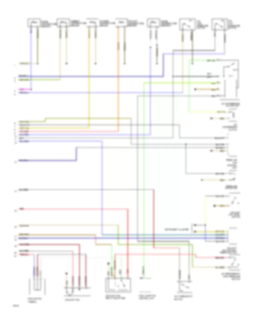
Электросхема кондиционера (1 из 2) для Audi 100 1991

Электросхема кондиционера (1 из 2) для Audi 100 1991 - Список элементов:
- (not used)
- 15a
- A/c control head
- A/c programmer
- Alternator
- Battery
- Coolant fan after run thermo switch
- Coolant fan relay-3rd stage
- Cooling fan after run control unit
- Cooling fan thermo switch
- Fuse
- Fuse 15a
- Fuse 25a
- Fuse 30a
- Fuse 5a
- Fuse/ relay panel
- Hot w/ lights on
- Hot w/ load reduction relay energized
- Ignition (15)
- Instrument cluster
- Interior temperature sensor 1 fan
- Red
- Tcm
- Temp regulator flap motor
Электросхема кондиционера (2 из 2) для Audi 100 1991
Электросхема кондиционера (2 из 2) для Audi 100 1991 - Список элементов:
- A/c compressor
- A/c compressor clutch unit
- A/c high pressure switch
- A/c low pressure switch
- A/c refrigerant high pressure
- A/c thermostat
- Ambient temperature sensor
- Clutch
- Control unit
- Coolant fan
- Coolant fan control thermo switch
- Coolant fan relay 2nd stage
- Coolant low level switch
- Coolant temperature sensor
- Cooling fan
- Fan
- Fresh air
- Fresh air fan motor
- Fuel injection control unit
- Inside temperature sensor 1
- Inside temperature sensor 2
- Instrument cluster
- Outside temperature sensor
- Red
- Switch
- Thermo