СИСТЕМА ОХЛАЖДЕНИЯ
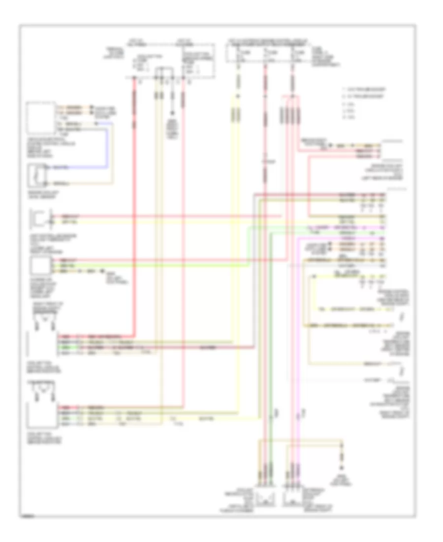
Электросхема системы охлаждения для Audi A8 L 2013
Электросхема системы охлаждения для Audi A8 L 2013 - Список элементов:
- (behind right kick panel) g43
- (right front of engine compt) coolant fan
- 11a
- 3.0l
- 4.0l
- 40a
- 6.3l
- 60a
- After-run coolant pump (4.0l) (left front of engine compt)
- Charge air cooling pump (except 6.3l) (under left headlamp)
- Computer data lines system
- Coolant fan 2
- Coolant fan control module (behind radiator)
- Coolant fan control module 2 (behind radiator)
- Coolant fan fuse
- Coolant fan second speed fuse
- Coolant recirculation pump (6.3l) (installed in plenum chamber)
- Engine control module (ecm) (center rear of engine compt)
- Engine coolant circulation pump 2 (4.0l) (left rear of engine)
- Engine coolant level sensor
- Engine coolant temperature (ect) sensor (front center of engine)
- Engine coolant temperature (ect) sensor on radiator outlet (4.0l) (right front of engine compt)
- Fuse 10a
- Fuse 15a
- Fuse 5a
- Fuse panel a (right side of engine compartment)
- G639 (on left kick panel)
- G685 (right front wheel well)
- Hot at all times
- Map controlled engine cooling thermostat (4.0l) (lower left front of engine)
- Nca
- Red
- T105
- T14b
- T16c
- T17g
- T2t
- T2u
- T32b
- T60
- T8ap
- T91
- T94
- Terminal 30 wire junction 2
- Vehicle electrical system control module module (behind left side of dash)
- W/ trailer socket
- W/o trailer socket
 Русский