СИСТЕМА ПЕРЕДАЧИ ДАННЫХ
Электросхема линии передачи данных CAN (1 из 3) для Audi Q7 4.2 2007

Электросхема линии передачи данных CAN (1 из 3) для Audi Q7 4.2 2007 - Список элементов:
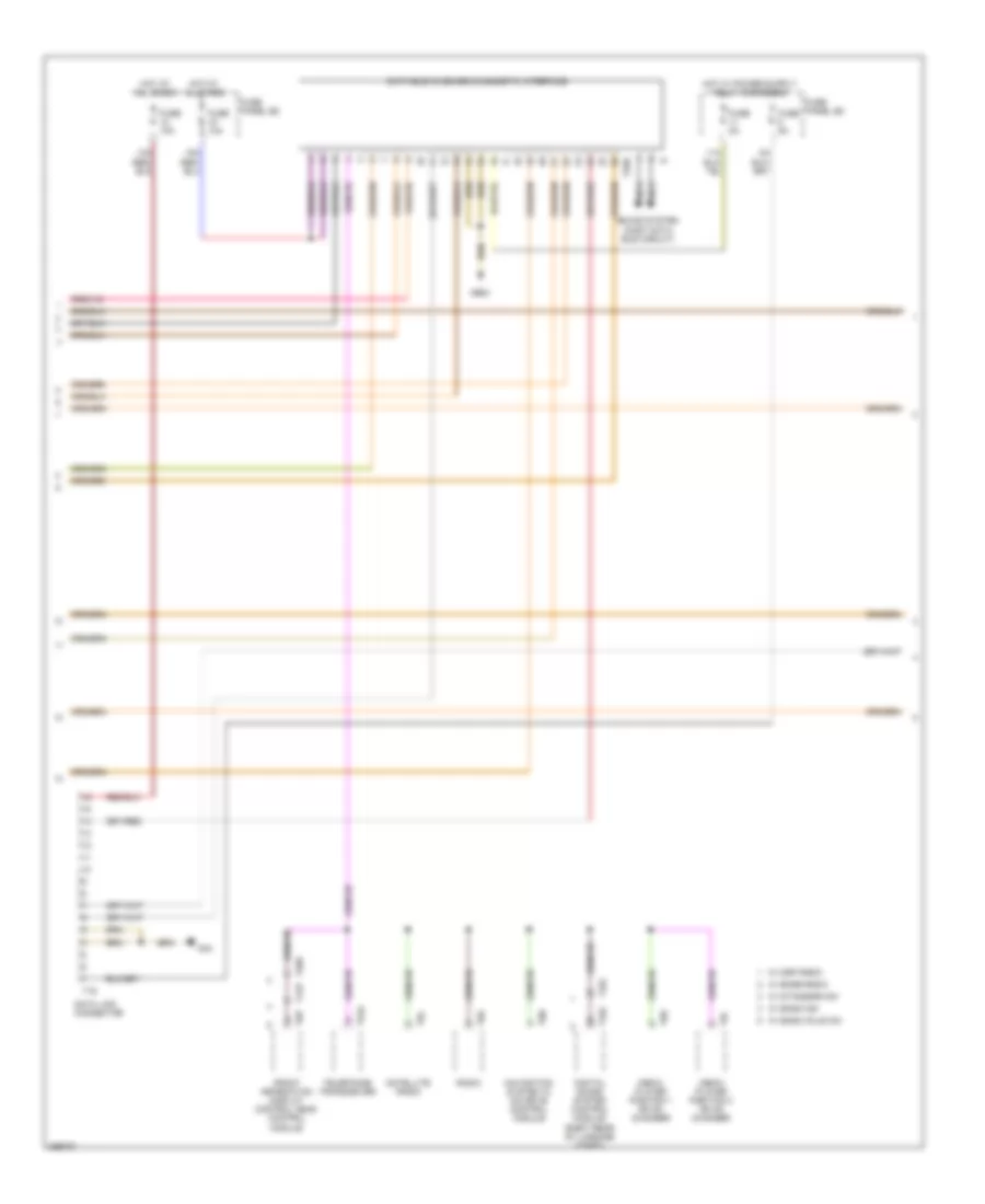
Электросхема линии передачи данных CAN (2 из 3) для Audi Q7 4.2 2007
Электросхема линии передачи данных CAN (2 из 3) для Audi Q7 4.2 2007 - Список элементов:
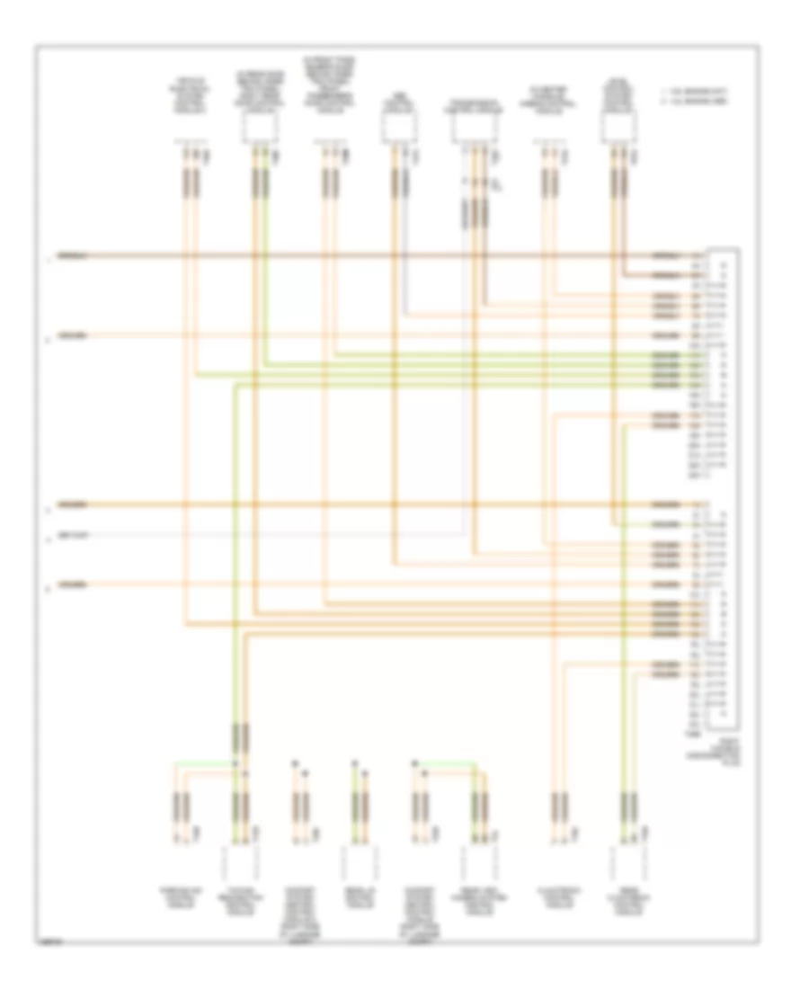
Электросхема линии передачи данных CAN (3 из 3) для Audi Q7 4.2 2007
Электросхема линии передачи данных CAN (3 из 3) для Audi Q7 4.2 2007 - Список элементов: