WARNING SYSTEMS
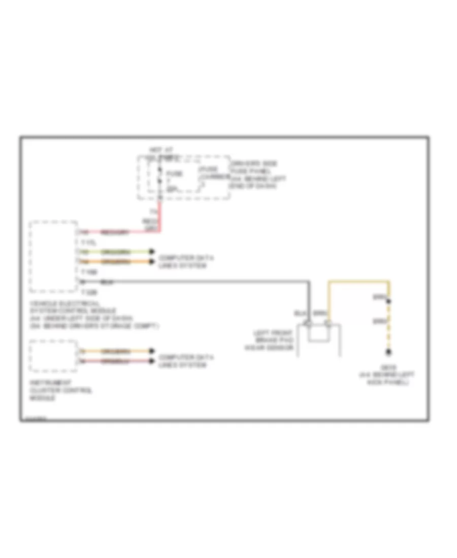
Brake Wear Sensor Wiring Diagram for Audi A4 2009
List of elements for Brake Wear Sensor Wiring Diagram for Audi A4 2009:
- Computer data lines system
- Driver's side fuse panel (a4: behind left end of dash)
- Fuse 20a
- Fuse carrier
- G639 (a4: behind left kick panel)
- Hot at all times
- Instrument cluster control module
- Left front brake pad wear sensor
- T16b
- T17l
- T32b
- Vehicle electrical system control module (a4: under left side of dash) (s4: behind driver's storage compt)
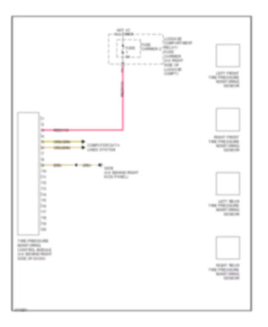
Tire Pressure Monitoring Wiring Diagram for Audi A4 2009
List of elements for Tire Pressure Monitoring Wiring Diagram for Audi A4 2009:
- Computer data lines system
- Fuse 5a
- Fuse carrier 2
- G638 (a4: behind right kick panel)
- Hot at all times
- Left front tire pressure monitoring sensor
- Left rear tire pressure monitoring sensor
- Luggage compartment relay/ fuse carrier (a4: right side of luggage compt)
- Right front tire pressure monitoring sensor
- Right rear tire pressure monitoring sensor
- Tire pressure monitoring control module (a4: behind right side of dash)

 Čeština
 Dansk
Dansk Deutsch
 Ελληνικά
 English
 English
 Español
 Suomi
Suomi Français
 Français
 עברית
עברית Hrvatski
 Magyar
 Italiano
 日本語
日本語 한국어
한국어 Nederlands
 Polski
 Português
 Português
 Română
 Slovenčina
 Slovenščina
 Svenska
 Türkçe
 中文 (中国)