ANTI-LOCK BRAKES
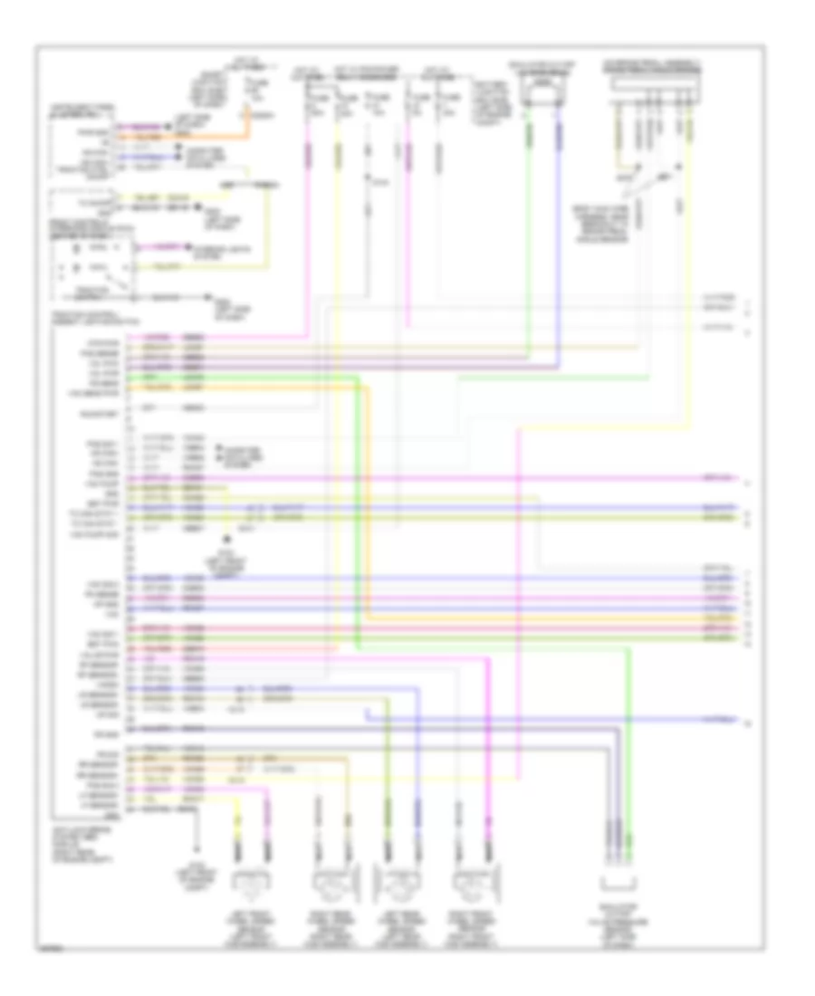
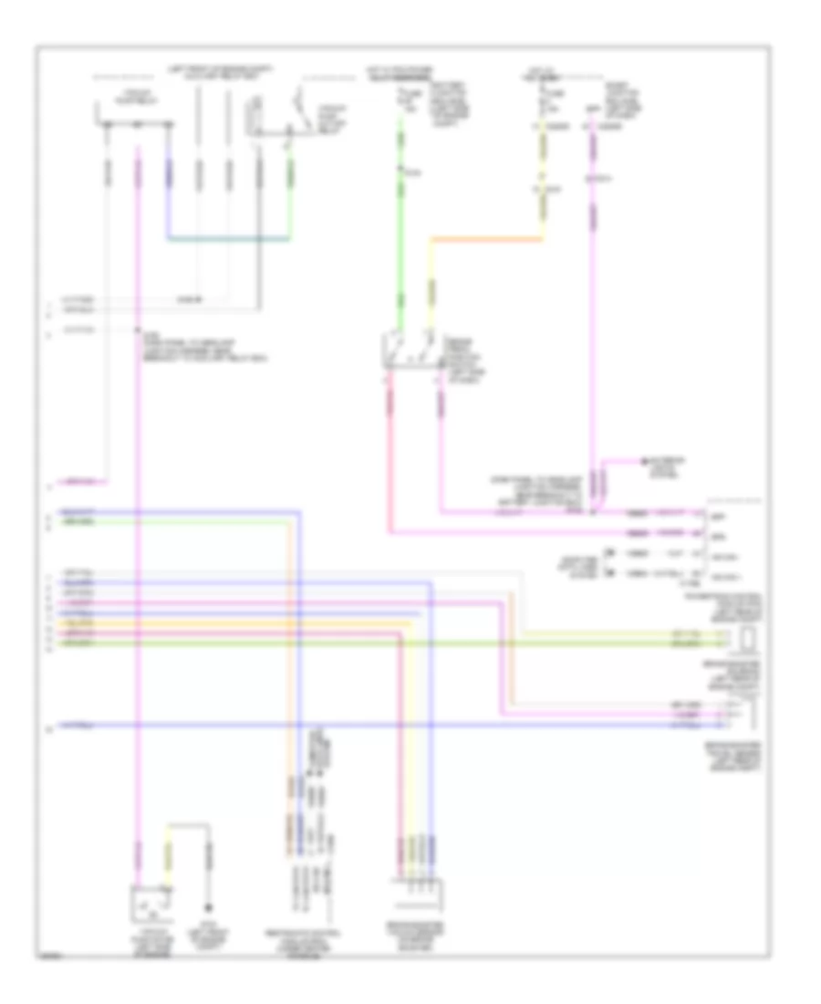
Anti-lock Brakes Wiring Diagram, Except Hybrid for Ford Fusion SE 2012

List of elements for Anti-lock Brakes Wiring Diagram, Except Hybrid for Ford Fusion SE 2012:
- (2.5l & 3.5l) (3.0l)
- (3.5l: dash panel to headlamp junction harness, near breakout to powertrain control module) s142
- 2.5l & 3.0l
- 2.5l/3.0l
- 20a
- 3.5l
- Anti-lock brake system (abs) module (right front of engine compt)
- Battery junction box (bjb) (left side of engine compt)
- Bpp
- Bpp input
- Bps
- Brake booster vacuum sensor (3.0l awd & 3.5l) (on brake booster)
- Brake pedal position switch (left side of dash)
- C139
- C144
- C175b
- C214
- C215
- C219
- C2280a
- C2280b
- C2280d
- C248
- C310b
- Cbp42
- Cca15
- Cca40
- Ccb08
- Ces09
- Computer data lines system
- Exterior lights system
- Front control interface module (fcim) (w/ navigation) (center of dash)
- Fuse 10a
- Fuse 15a
- Fuse 30a
- Fuse 40a
- Fusion
- G104 (2.5l & 3.0l: right front of engine compt) (3.5l: right side of engine compt)
- G202 (left side of dash)
- Gd116
- Gd123
- Gnd
- Hot at all times
- Hot in run or start
- Hot w/ pcm power relay energized
- Hs can +
- Hs can -
- Hs can+
- Hs can-
- Instrument panel cluster (ipc)
- Interior lights system
- Ivd pwr
- Ivd rtn
- Lca37
- Left front wheel speed sensor (left front hub assembly)
- Left rear wheel speed sensor (left rear hub assembly)
- Lf sensor+
- Lf sensor-
- Lr sensor+
- Lr sensor-
- Mkz
- Mtr gnd
- Mtr pwr
- Nca
- Powertrain control module (pcm) (left rear of engine compt)
- Pwr gnd
- Rca17
- Rca18
- Rca19
- Rca20
- Rca37
- Rca40
- Restraints control module (rcm) (under center console)
- Rf sensor+
- Rf sensor-
- Right front wheel speed sensor (right front hub assembly)
- Right rear wheel speed sensor (right rear hub assembly)
- Rr sensor+
- Rr sensor-
- Run/start
- S120
- S140
- Sas a
- Sas b
- Sbb08
- Sbb10
- Smart junction box (sjb) (left side of dash)
- Solid state
- Steering angle sensor module (sasm) (3.5l) (center of steering column)
- Switch traction
- Tc can stat +
- Tc can stat -
- Tc can stat+
- Tc can stat-
- Traction control/ambient lighting switch
- Traction ctl on/off
- Vac gnd
- Vac pwr
- Vac sig
- Valve pwr
- Vca03
- Vca04
- Vca05
- Vca06
- Vca23
- Vca24
- Vca38
- Vca41
- Vca42
- Vdb04
- Vdb05
- Vdbo4
- Vdbo5
Anti-lock Brakes Wiring Diagram, Hybrid (1 of 2) for Ford Fusion SE 2012
List of elements for Anti-lock Brakes Wiring Diagram, Hybrid (1 of 2) for Ford Fusion SE 2012:
- (body main wire harness, near breakout to brake pedal angle sensor)
- (left side of dash) g202
- (on brake pedal assembly) brake pedal angle sensor
- Anti-lock brake system (abs) module (right rear of engine compt)
- Battery junction box (bjb) (left side of engine compt)
- Bst pwm
- Bst pwr
- C219
- C2280a
- Cbb30
- Cbb31
- Cbb32
- Cbb37
- Cbk03
- Cca15
- Cca22
- Ccb30
- Ccb33
- Computer data lines system
- Front controls interface module (fcim) (center of dash)
- Fuse 10a
- Fuse 30a
- Fuse 50a
- Fuse 5a
- Fusion
- G103 (left front of engine compt)
- G202 (left side of dash)
- Gd116
- Gd121
- Gnd
- Hot at all times
- Hot w/ pcm power relay energized
- Hs can+
- Hs can+ traction ctrl on/off
- Hs can-
- Instrument panel cluster (ipc)
- Interior lights system
- Lca16
- Lca27
- Lca37
- Left front wheel speed sensor (left front hub assembly)
- Left rear wheel speed sensor (left rear hub assembly)
- Lf sensor+
- Lf sensor-
- Lr sensor+
- Lr sensor-
- Mkz
- Mp gnd
- Mp sig
- Mtr pwr
- Nca
- Pas gnd
- Pas sense
- Pas sig 1
- Pas sig 2
- Pm sense
- Ps gnd
- Ps sens
- Ps sig
- Pwr gnd
- Rca16
- Rca17
- Rca18
- Rca19
- Rca20
- Rca27
- Rca37
- Rcb33
- Rf sensor+
- Rf sensor-
- Right front wheel speed sensor (right front hub assembly)
- Right rear wheel speed sensor (right rear hub assembly)
- Rr sensor+
- Rr sensor-
- Run/start
- S144
- S270
- S271
- Sbb08
- Sbb10
- Simulator cut-off valve pressure sensor (left side of dash)
- Simulator cut-off valve solenoid
- Smart junction box (sjb) (left side of dash)
- Tc can stat +
- Tc can stat -
- Tc on/off
- Traction control/ ambient lighting switch
- Traction switch
- Vac
- Vac pump
- Vac pump mon
- Vac sens pwr
- Vac sig 1
- Vac sig 2
- Vacrc
- Valve pwr
- Vca03
- Vca04
- Vca05
- Vca06
- Vca13
- Vca22
- Vca23
- Vca24
- Vca30
- Vca38
- Vca39
- Vca43
- Vcb34
- Vdb04
- Vdb05
- Vol pwm
- Vol pwr
Anti-lock Brakes Wiring Diagram, Hybrid (2 of 2) for Ford Fusion SE 2012
List of elements for Anti-lock Brakes Wiring Diagram, Hybrid (2 of 2) for Ford Fusion SE 2012:
- (dash panel to headlamp junction harness, near breakout to battery junction box) s142
- (left front of engine compt) auxiliary relay box
- Battery junction box (bjb) (left side of engine compt)
- Bpp
- Bps
- Brake booster solenoid (left rear of engine compt)
- Brake booster travel sensor (left rear of engine compt)
- Brake booster vacuum sensor (on brake booster)
- Brake pedal position switch (left side of dash)
- C175b
- C214
- C219
- C2280b
- C2280d
- C310b
- Ceb08
- Ces09
- Computer data lines system
- Exterior lights system
- Fuse 15a
- G103 (left front of engine compt)
- Hot at all times
- Hot w/ pcm power relay energized
- Hs can +
- Hs can -
- Powertrain control module (pcm) (left rear of engine compt)
- Restraints control module (rcm) (under center console)
- S140
- S190
- S192 (dash panel to headlamp junction harness, near breakout to auxiliary relay box)
- Smart junction box (sjb) (left side of dash)
- System data lines computer
- Tc can stat+
- Tc can stat-
- Vacuum pump cut-off relay
- Vacuum pump motor (left side of engine)
- Vacuum pump relay
- Vca23
- Vca24
- Vdb04
- Vdb05