БЛОК ПРЕДОХРАНИТЕЛЕЙ И РЕЛЕ
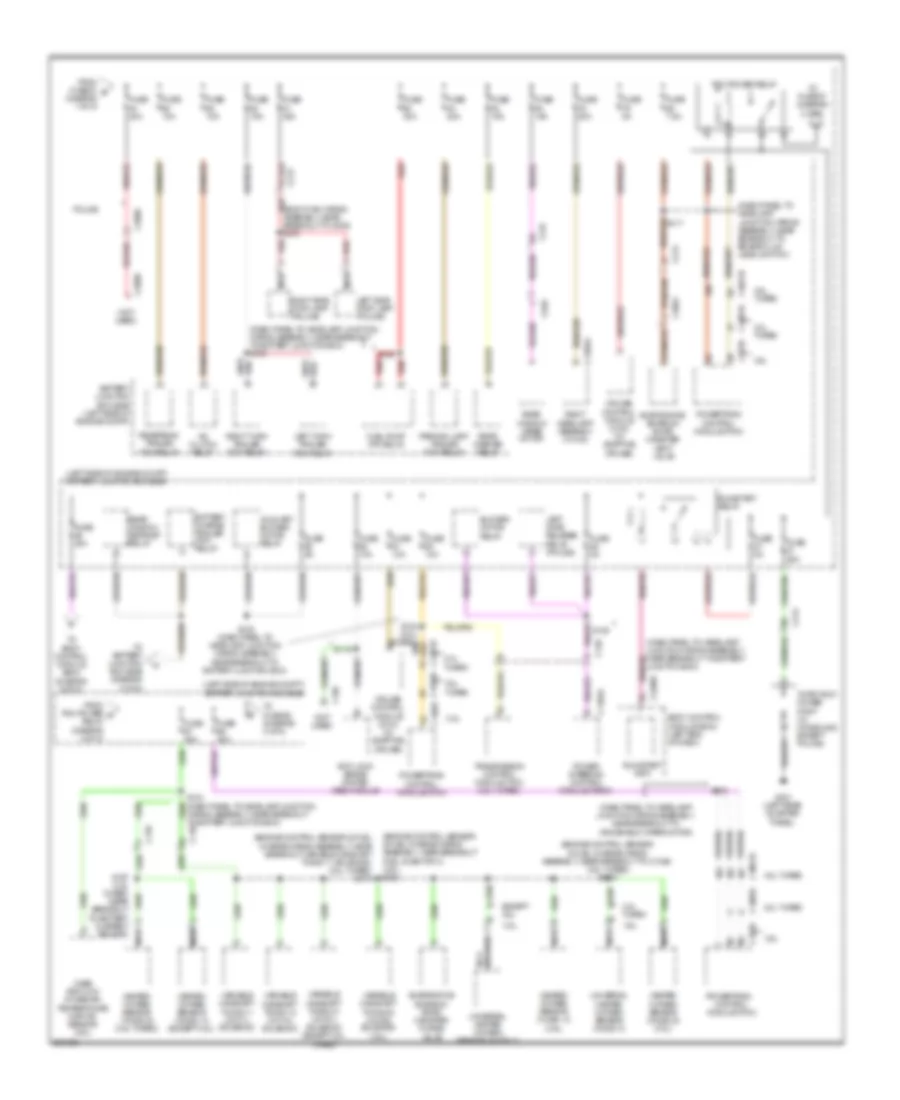
Электросхема блока предохранителей и реле (1 из 5) для Ford Explorer XLT 2013

Электросхема блока предохранителей и реле (1 из 5) для Ford Explorer XLT 2013 - Список элементов:
- (battery cable wiring assembly, in breakout to c1750) s105
- (body main wiring assembly, near breakout to c213) s300
- (left side of engine compt) battery junction box (bjb)
- (main wiring harness, near breakout to hvac module) s213
- (not used)
- Anti-lock brake system (abs) module
- Auxiliary blower motor relay
- Battery
- Battery charge trailer tow relay
- Battery junction box (bjb) (left side of engine compt)
- Blower motor relay
- Brake pedal position (bpp) switch
- Breakout to g100) (2.0l: near breakout to high current battery junction box) (3.5l gas: near breakout to starter motor)
- C1284a
- C139
- C1463b
- C1617a
- C1617b
- C1617c
- C1617d
- C210
- C212
- C213
- C228b
- C237
- C260
- C2606
- C2608
- C311
- C312
- C3133
- C3134
- C317
- C319
- C3265a
- C341a
- C4174a
- Driver seat module (dsm)
- Driver side front seat control switch
- Dual climate controlled seat module (dcsm) (if equipped)
- Except police
- Front console power point
- Front wiper relay
- Fuse 10a
- Fuse 15a
- Fuse 20a
- Fuse 30a
- Fuse 40a
- Fuse 40a 30a
- Fuse 50a
- Fuse b 100a
- Fuse e 100a
- Fuse f 60a
- Fusible link a (10 ga- red)
- Fusible link b (10 ga- red)
- G200 (under left front of center console)
- Generator
- High current battery junction box (bjb) (left rear of engine compt)
- High fan cooling (hfc) relay
- Hvac module (w/ heated seats)
- Instrument panel power point
- Instrument panel power point 2
- Left headlamp assembly (w/ hid)
- Left second row power release seat motor
- Liftgate/ trunk module (ltm)
- Low fan cooling (lfc) relay
- Passenger side front seat control switch
- Police
- Power steering control module (pscm)
- Rear console power point (w/ console except police)
- Rear window defrost relay
- Red
- Right rear power point (police)
- Right second row power release seat motor
- Roof opening panel module
- S100 (3.5l: near breakout to starter motor) (2.0l: near breakout to c1750)
- S101 (3.5l: near breakout to starter motor) (2.0l: near breakout to high current battery junction box)
- S102 (3.5l flex fuel: near red
- S341
- Starter motor
- Starter relay
- Third row power seat relay
- To battery junction box (bjb) (diagram 5 of 5)
- To body control module (bcm) (diagram 3 of 5)
- To dc/ac inverter module (diagram 4 of 5)
- To fuse 40 (diagram 2 of 5)
- Trailer brake control (tbc) module connector
- Transmission cntrol module (tcm) (2.0l turbo)
- W/ 10-way power seat
- W/ 6-way power seat
- W/ console
- W/ memory
- W/o console
- W/o memory
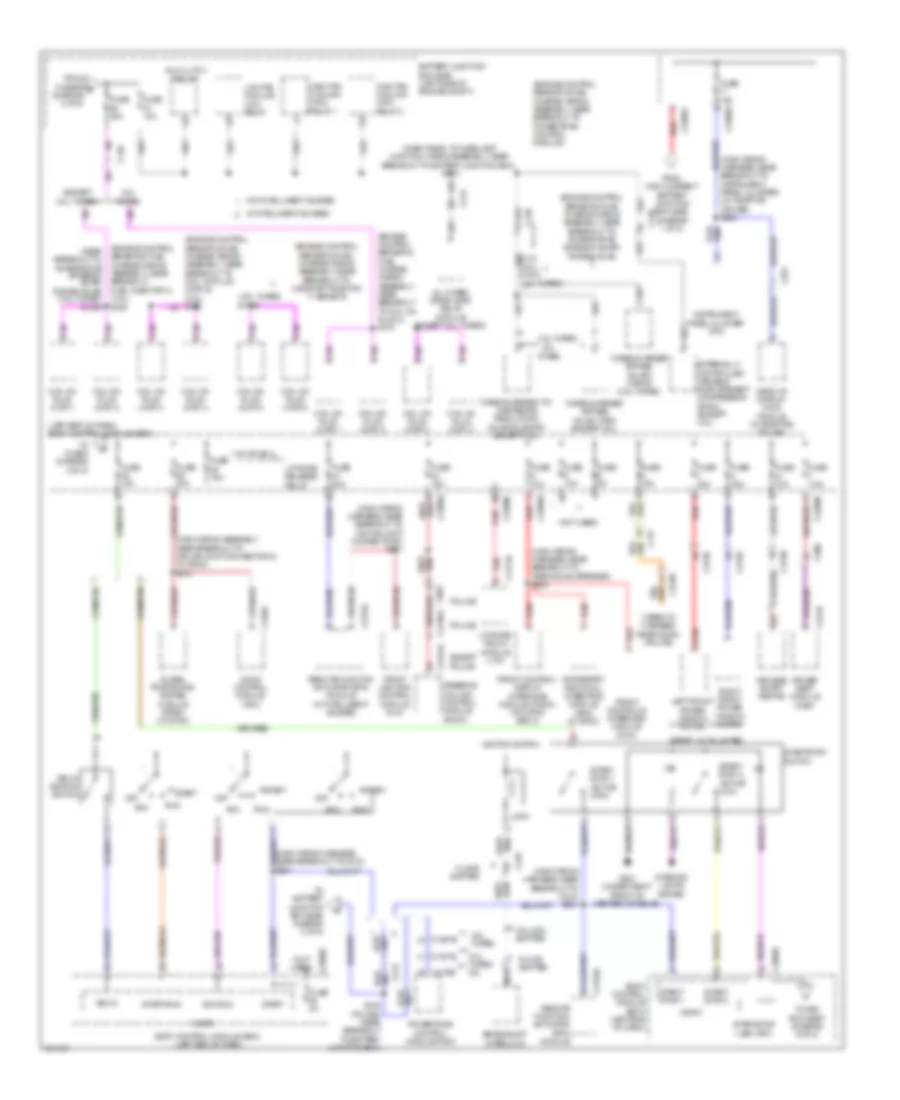
Электросхема блока предохранителей и реле (2 из 5) для Ford Explorer XLT 2013
Электросхема блока предохранителей и реле (2 из 5) для Ford Explorer XLT 2013 - Список элементов:
- (body main wiring assembly, near breakout to g300) s373
- (dash panel to headlamp junction wiring assembly, near breakout to battery junction box)
- (dash panel to headlamp junction wiring assembly, near breakout to battery junction box) s130
- (dash panel to headlamp junction wiring assembly, near breakout to brake fluid level switch)
- (dash panel to headlamp junction wiring assembly, near breakout to windshield wiper motor)
- (engine control sensor & fuel charge wiring assembly, near breakout fuel injector 3) (3.5l) s154
- (engine control sensor & fuel charge wiring assembly, near breakout to c1045) (3.5l turbo) s1001
- (engine control sensor & fuel charge wiring assembly, near breakout variable camshaft timing 11 solenoid) (2.0l turbo) s173
- (left side of engine compt) battery junction box (bjb)
- (not used)
- 2.0l turbo
- 3.5l
- 3.5l turbo
- A/c clutch relay
- Anti-lock brake system (abs) module
- Auxiliary blower motor relay
- Battery charge trailer tow relay
- Battery junction box (bjb) (left side of engine compt)
- Blower motor relay
- Body control module (bcm) (left end of dash)
- C1285a
- C1381b
- C139
- C140
- C1463a
- C1551b
- C175b
- C213
- C2280f
- C2606
- C2608
- C3053
- C935
- Cruise control module (ccm) (w/ adaptive cruise)
- Evaporative emission (evap) canister purge valve
- Evaporative emission (evap) canister vent valve
- Except 3.5l
- From fuse 61 b (diagram 1 of 5)
- From pcm power d relay (diagram 2 of 5)
- Fuel pump (fp) relay
- Fuse 10a
- Fuse 15a
- Fuse 20a
- Fuse 30a
- Fuse 40a
- Fuse 5a
- Fuse 7.5a
- G301 (left rear quarter panel)
- Heated oxygen sensor (ho2s) 12 (3.5l)
- Heated oxygen sensor (ho2s) 12 (except 3.5l)
- Heated oxygen sensor (ho2s) 22 (3.5l turbo)
- Heated oxygen sensor (ho2s) 22 (3.5l)
- Left gate release relay (police)
- Left side stop lamp (police)
- Left turn trailer tow relay
- Mass air flow/ intake air temperature (maf/iat) sensor (3.5l)
- Nca
- Parking lamp trailer tow relay
- Pcm power relay
- Police
- Power steering control module (pscm)
- Powertrain control module (pcm)
- Rear washer relay
- Rear window defrost relay
- Rear window wiper motor
- Red
- Reversing trailer tow relay
- Right headlamp assembly (w/ hid)
- Right side stop lamp (police)
- Right turn trailer tow relay
- Run/start (fet)
- Run/start relay
- S115
- S119
- S123
- S125 (dash panel to headlamp junction wiring assembly, near breakout to battery junction box)
- S129
- Third row power point (w/ console & except police)
- To battery junction box (bjb) (diagram 5 of 5)
- To body control module (bcm) (diagram 5 of 5)
- To fuse 67 (diagram 2 of 5)
- To fuse 68 (diagram 3 of 5)
- Transmission control module (tcm) (2.0l turbo)
- Universal heated oxygen sensor (ho2s) 11
- Universal heated oxygen sensor (ho2s) 21
- Variable camshaft timing 11 (vct11) solenoid
- Variable camshaft timing 12 (vct12) solenoid
- Variable camshaft timing 21 (vct21) solenoid (except 2.0l turbo)
- Variable camshaft timing 22 (vct22) solenoid (3.5l)
- Wiring assembly, near breakout to battery junction box)
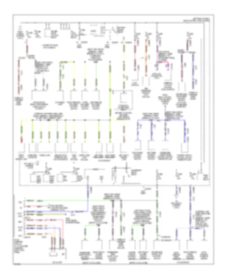
Электросхема блока предохранителей и реле (3 из 5) для Ford Explorer XLT 2013
Электросхема блока предохранителей и реле (3 из 5) для Ford Explorer XLT 2013 - Список элементов:
- (3.5l turbo) s1009
- (3.5l) s155
- (dash panel to headlamp junction wiring assembly, near breakout to battery junction box) s113
- (engine control sensor & fuel charge wiring assembly, near breakout fuel injector 3)
- (engine control sensor & fuel charge wiring assembly, near breakout to camshaft position 11 sensor)
- (engine control sensor & fuel charge wiring assembly, near breakout to coil on plug 2) s175
- (engine control sensor & fuel charge wiring assembly, near breakout to evaporative emission (evap) purge valve)
- (engine control sensor & fuel charge wiring assembly, near breakout to powertrain control module)
- (except 2.0l turbo)
- (left end of dash) body control module (bcm)
- (main wiring assembly, near breakout to hs-can joint connector 6) (w/ sync) s212
- (main wiring harness, near breakout to c212) s201
- (main wiring harness, near breakout to hs-can joint connector 6) s211
- (main wiring harness, near breakout to instrument panel cluster) (w/ adaptive cruise) s204
- (main wiring harness, near breakout to parking aid speaker) s203
- (near breakout to evaporative emission (evap) purge valve) (3.5l turbo) s1002
- (not used)
- (taped to harness near c2238) (police)
- 2.0l turbo
- 2.0l turbo 3.5l
- 3.5l turbo
- A/c clutch relay
- Acc
- Acc/run
- Accessory protocol interface module (apim) (w/ sync)
- All wheel drive (awd) relay module (except 2.0l turbo)
- Audio control module (acm)
- Battery junction box (bjb) (left side of engine compt)
- Body control module (bcm) (left end of dash)
- Brake shift interlock
- C1381b
- C139
- C140
- C1551b
- C175b
- C211
- C212
- C213
- C2153c
- C2238
- C2280a
- C2280b
- C2280d
- C2280g
- C237
- C240a
- C2414a
- C263
- C291
- C300
- C3138
- C3139
- C341b
- C4174a
- Coil on plug (cop) 1
- Coil on plug (cop) 2
- Coil on plug (cop) 3
- Coil on plug (cop) 4
- Coil on plug (cop) 5
- Coil on plug (cop) 6
- Column shifter
- Driver seat module (dsm)
- Except police
- Externally controlled variable displacement compressor (evdc) (except 3.5l)
- Floor shifter
- From fuse 69 e (diagram 2 of 5)
- From high current battery junction box (bjb) (diagram 1 of 5)
- Front control/ display interface module (fcdim) (w/o sync gen 2)
- Front controls interface module (fcim)
- Front lighting control module (flm)
- Fuse 10a
- Fuse 15a
- Fuse 20a
- Fuse 30a
- Fuse 5a
- Fuse 7.5a
- G201 (under right front of center console)
- Global positioning system module (gpsm) (w/ sync)
- Head up display (hud) module (w/ adaptive cruise)
- High fan cooling (hfc) relay 1
- High fan cooling (hfc) relay 2
- Ignition switch
- Instrument panel cluster (ipc)
- Interior lights system
- Key in
- Key in ignition switch
- Keyless entry keypad
- Left front power window motor
- Liftgate release relay
- Liftgate/ trunk module (ltm)
- Lock
- Low fan cooling (lfc) relay
- Micro
- Nca
- Off
- Police
- Powertrain control module (pcm)
- Red
- Remote function actuator (rfa) module
- Remote function actuator (rfa) module (w/ intelligent access)
- Right front power window motor
- Run
- S180 (police) (near breakout to battery junction box)
- Sport, xlt & limited
- Start
- Start/ stop 1
- Start/ stop 1 (active high)
- Start/ stop 2
- Start/ stop 2 (active low)
- Start/run
- Start/stop (led) (fet)
- Start/stop switch
- Steering column control module (sccm)
- To 3rd row seat (diagram 5 of 5)
- To battery junction box (bjb) diagram 5 of 5)
- To fuse 5 (diagram 4 of 5)
- Turbocharger (tc) wastegate regulating valve solenoid (except 3.5l)
- Turbocharger bypass valve (tcby) (except 3.5l)
- Turbocharger bypass valve 2 (tcby2) (3.5l turbo)
- W/ intelligent access
- W/o intelligent access
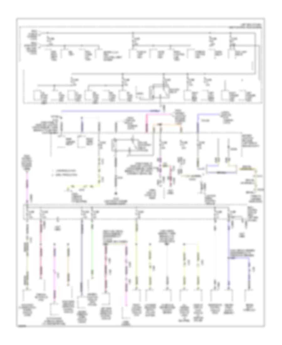
Электросхема блока предохранителей и реле (4 из 5) для Ford Explorer XLT 2013
Электросхема блока предохранителей и реле (4 из 5) для Ford Explorer XLT 2013 - Список элементов:
- (body main wiring assembly, near breakout to c213) (w/ second/ third row folding seats) s305
- (body main wiring assembly, near breakout to g300) s303
- (body main wiring assembly, near breakout to hs-can joint connector 4) s332
- (interior lamp feed headliner wiring assembly, near breakout to left vanity mirror lamp) (w/ moonroof) s900
- (interior lamp feed headliner wiring assembly, near breakout to left vanity mirror lamp) s901
- (left end of dash) body control module (bcm)
- (left front door window regulator wiring harness, near breakout driver's door side impact sensor) (sport, xlt & limited) s500
- (main wiring assembly, near breakout to instrument panel cluster) s205
- (not used)
- (right front door window regulator wiring assembly, near breakout passenger's door lock switch) (sport, xlt & limited) s604
- (taped to harness near c2238)
- (taped to harness near c2238) (police)
- Ac outlet
- Ac-a c3501b
- Ac-b
- Acc
- Acc rly
- Accessory delay relay
- All lock/ unlock relay
- Audio digital signal processing (dsp) module (w/ sony)
- Auto- dimming interior mirror
- Battery junction box (bjb) (left side of engine compt)
- Battery saver relay
- C210
- C211
- C213
- C219
- C2238
- C2280a
- C2280b
- C2280d
- C2280f
- C228a
- C237
- C238
- C2414b
- C300
- C3138
- C3139
- C3154c
- C316
- C317
- C327
- C535b
- Cargo lamp
- Cargo task lamp (police)
- Cbp32
- Data link connector (dlc)
- Dc/ac inverter module (w/ 110v power inverter) (right kick panel)
- Driver door unlock relay
- Driver side door lock control switch
- Driver side front seat control switch (w/ 10-way power seat & memory)
- Except police
- Except police &
- From battery junction box (bjb) (diagram 1 of 5)
- From body control module (bcm) (diagram 4 of 5)
- From fuse 28 (diagram 3 of 5)
- Fuse 10a
- Fuse 15a
- Fuse 20a
- Fuse 30a
- Fuse 5a
- G302 (right rear quarter panel)
- Gd348
- Glove box lamp
- Gnd c3501a
- Hvac module
- Hya01
- Hya02
- Led+
- Led-
- Left front power window motor
- Left high beam (fet)
- Left rear window control switch
- Left second row seat control switch
- Left side rail lamp
- Left vanity mirror lamp
- Lin
- Lin 01
- Lya03
- Master window control switch
- Master window control switch (base & police)
- Micro
- Overhead console
- Park lamp relay
- Passenger side door lock control switch
- Passenger side window control switch
- Passenger window side control switch (base & police)
- Police
- Red
- Rev lp (fet)
- Right front power window motor
- Right high beam (fet)
- Right rear window control switch
- Right second row seat control switch
- Right side rail lamp
- Right vanity mirror lamp
- Roof opening panel control switch
- Roof opening panel module
- Rya03
- Sbb17
- Second row interior lamp (w/o moonroof)
- Sport, xlt & limited
- Steering column control module (sccm)
- Stop/ chmsl (fet)
- Task lamp (police)
- Third row power seat relay
- Third row seat control switch
- Tire pressure monitor (tpm) module
- To fuse 18 (diagram 5 of 5)
- To splice s310 (diagram 4 of 5)
- Vdn01
- W/ memory
- W/ moonroof
- W/o console
- W/o memory
Электросхема блока предохранителей и реле (5 из 5) для Ford Explorer XLT 2013
Электросхема блока предохранителей и реле (5 из 5) для Ford Explorer XLT 2013 - Список элементов:
- (body main wiring wiring assembly, near breakout to c312) (w/ rear view camera) s328
- (dash panel to headlamp junction s184 wiring assembly, near breakout to left front corner flashing led)
- (if equipped)
- (left end of dash) body control module (bcm)
- (main wiring assembly, near breakout to hs-can joint connector 6) s217
- (main wiring harness, near breakout to parking aid speaker) s202
- (not used)
- (taped to harness near c2238)
- 3rd row seat (fet)
- All terrain control module (atcm)
- Auto-dimming interior mirror (w/ lane departure)
- Back lighting led (fet)
- Battery junction box (bjb) (left side of engine compt)
- Body control module (bcm) (left end of dash)
- Box (bjb) (diagram 1 of 5)
- Brake shift interlock
- Bsi (fet)
- C1830
- C212
- C213
- C2238
- C2280b
- C2280d
- C2280e
- C2280f
- C237
- C263
- C291
- C310a
- C312
- C317
- C405
- C465
- C4808a
- C494
- C919
- C935
- Center stack switch assembly
- Diode
- Early production
- Fog lamp relay
- From battery junction box (bjb) (diagram 2 of 5)
- From battery junction l
- From fuse 39 k (diagram 4 of 5)
- From splice s125 (diagram 2 of 5)
- From splice s180 (diagram 3 of 5)
- From start/stop h (led) (fet) (diagram 3 of 5)
- Front lighting control module (flm)
- Front wiper relay
- Fuse
- Fuse 10a
- Fuse 15a
- Fuse 20a
- Fuse 2a
- Fuse 5a
- Fuse 7.5a
- G103 (left front corner of engine compt)
- Generic function module (gfm) (police)
- Head up display (hud) module (w/ adaptive cruise)
- Heated steering wheel module (hswm)
- Horn relay
- In-vehicle temperature/ humidity sensor
- Interior lighting (fet)
- Keypad illum (fet) (w/o intelligent access)
- Late production
- Left corner lamp (fet)
- Left low beam (fet)
- Left side obstacle detection control module
- Lf turn lamp (fet)
- Lighting/ siren control module
- Low gear selector switch (column shifter)
- Lr stop/ turn lamp (fet)
- Lr turn lamp (fet)
- Micro
- Nca
- Occupant classification system module (ocsm)
- Parking aid module (pam)
- Pcm wake up (fet)
- Police
- Police run/start relay (police)
- Puddle lamp (fet)
- Rain sensor module (if equipped)
- Rear washer relay
- Restraints control module (rcm)
- Rf turn lamp (fet)
- Right corner lamp (fet)
- Right low beam (fet)
- Right side obstacle detection control module
- Rr stop/ turn lamp (fet)
- Rr turn lamp (fet)
- Run/acc relay
- S122 (dash panel to headlamp junction wiring assembly, near breakout to battery junction box)
- S126
- S181
- Video camera
- Warn module (w/ grille prep)
- White light (fet)