СИСТЕМА КОНДИЦИОНЕРА
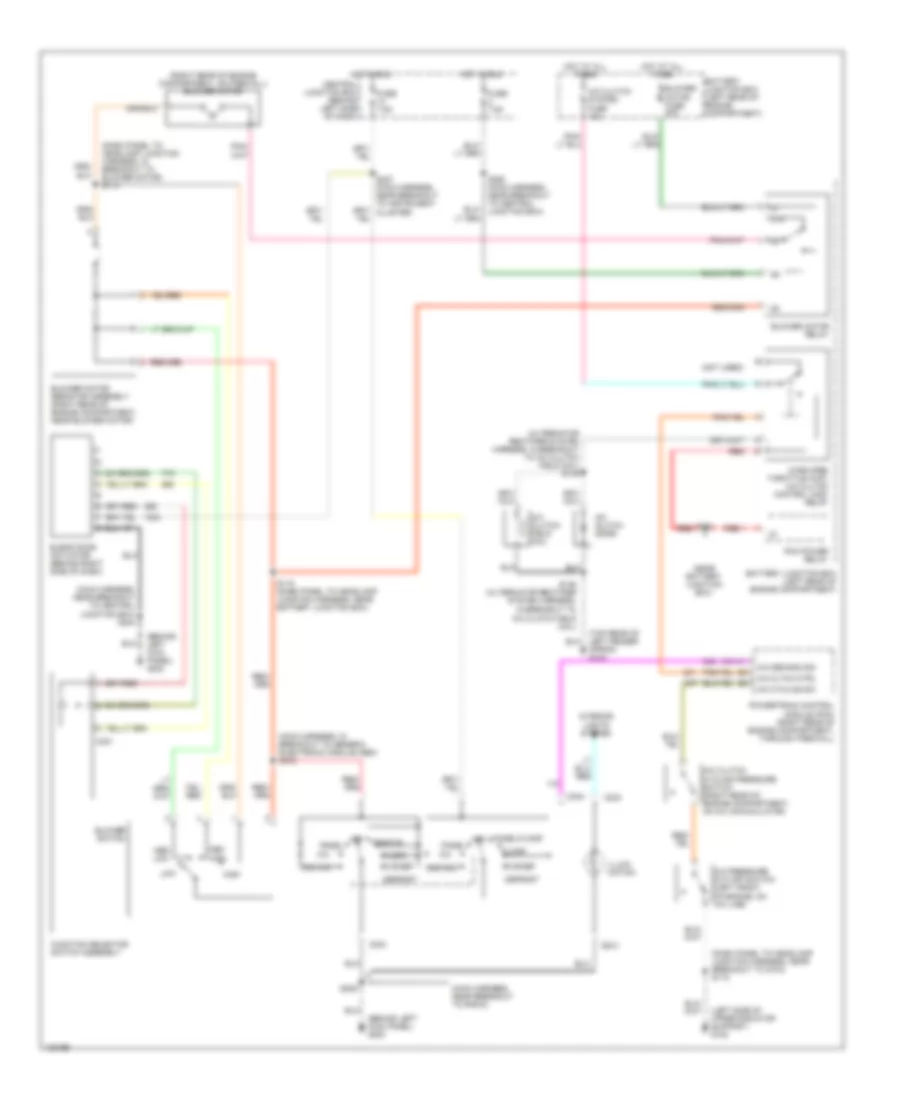
схема нагревателя для Ford Ranger 2000
 https://portal-diagnostov.com/license.html
Automotive Electricians Portal FZCO
Automotive Electricians Portal FZCO
https://portal-diagnostov.com/license.html
https://portal-diagnostov.com/license.html
Automotive Electricians Portal FZCO
Automotive Electricians Portal FZCO
схема нагревателя для Ford Ranger 2000 - Список элементов:
- (main harness, near breakout to radio)
- (top rear of left fender apron) g104
- 87a
- Battery junction box (left rear of engine compartment)
- Blower motor (right rear of engine compartment on firewall)
- Blower motor fuse 40a
- Blower motor relay
- Blower motor resistor assembly (right rear of engine compartment, near blower motor)
- Blower switch
- C233
- C234
- Central junction box (behind left side of dash)
- Defrost
- Floor
- Flr/def
- Function selector switch assembly
- Fuse 7.5a
- High
- Hot at all times
- Hot in run
- Illumi- nation
- Interior lights system
- Low
- Med high
- Med low
- Off
- Panel
- Panel/ floor
- S114 (dash panel to headlamp junction harness, in breakout to blower motor)
- S115 (dash panel to headlamp junction harness, near battery junction box)
- S209
- S212 (main harness, in breakout to generic electronic module (gem))
- S250 (main harness, near breakout to central junction box)
Электросхема кондиционера с ручный управлением для Ford Ranger 2000
Электросхема кондиционера с ручный управлением для Ford Ranger 2000 - Список элементов:
- (alternator rectifier system harness, in breakout to a/c clutch field coil) s145
- (behind left kick panel) g200
- (dash panel to headlamp junction harness, in breakout to blower motor) s114
- (dash panel to headlamp junction harness, near breakout to g104) s118
- (left side of upper radiator support) g108
- (main harness, in breakout to generic electronic module (gem) s212
- (main harness, near breakout to radio)
- (main harness, near breakout to central junction box) s244
- (near battery junction box)
- (not used)
- (right rear of engine compartment, on firewall) blower motor
- (top rear of left fender apron) g104
- 87a
- A/c
- A/c cltch ctrl
- A/c clutch cycling pressure switch (right rear of engine compartment, on a/c accumulator)
- A/c clutch diode
- A/c clutch field coil
- A/c clutch system fuse 10a
- A/c cycling sw
- A/c demand sig
- A/c pressure cut-off switch (left front of engine, on a/c line)
- Battery junction box (left rear of engine compartment)
- Blend door actuator (behind right side of dash)
- Blower motor fuse 40a
- Blower motor relay
- Blower motor resistor assembly (right rear of engine compartment, near blower motor)
- Blower switch
- C231
- C233
- C234
- Central junction box (behind left side of dash)
- Defrost
- Floor
- Flr/def
- Function selector switch assembly
- Fuse 7.5a
- High
- Hot at all times
- Hot in run
- Illumi- nation
- In breakout to a/c clutch field coil)
- Interior lights system
- Low
- Max a/c
- Med high
- Med low
- Off
- Pan/flr
- Panel
- Panel/floor
- Pcm power relay
- Powertrain control module (pcm) (right rear of engine compartment, through firewall)
- Red
- S115 (dash panel to headlamp junction harness, near battery junction box)
- S121
- S146 (alternator rectifier system harness,
- S209
- S227 (main harness, near breakout to instrument cluster)
- S250 (main harness, near breakout to central junction box)
- Wide open throttle (wot) a/c clutch control (acc) relay

 Čeština
 Dansk
Dansk Deutsch
 Ελληνικά
 English
 English
 Español
 Suomi
Suomi Français
 Français
 עברית
עברית Hrvatski
 Magyar
 Italiano
 日本語
日本語 한국어
한국어 Nederlands
 Polski
 Português
 Português
 Română
 Slovenčina
 Slovenščina
 Svenska
 Türkçe
 中文 (中国)