СИСТЕМА КОНДИЦИОНЕРА
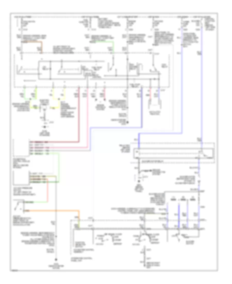
схема нагревателя для Ford ZX2 2002


схема нагревателя для Ford ZX2 2002 - Список элементов:
- (behind right side of dash) g201
- (dash panel to headlamp s213
- (main harness, in breakout to integrated control panel (icp), near breakout to rear window defrost switch)
- .33 ohms
- .62 ohms
- 1.3 ohms
- 87a
- Blower c.b. 30a
- Blower motor (behind right side of dash, in a/c-heater plenum)
- Blower motor relay
- Blower motor resistor (behind right side of dash, in a/c-heater plenum)
- Blower switch
- C200
- C220
- C272
- C273
- C277
- Central junction box (behind left side of dash)
- Defrost
- Floor
- Floor/defrost
- Function selector switch
- G224 (behind left kick panel)
- Ground distribution system
- Harness, near breakout to multi-function switch)
- Heater control assembly
- High
- Hot at all times
- Hot in run
- Integrated control panel (icp)
- J/c 3
- Low
- Off
- Panel
- Panel floor
- Relay box (behind left side of dash)
- S238
- Wiper fuse 20a
Электросхема кондиционера с ручный управлением для Ford ZX2 2002
Электросхема кондиционера с ручный управлением для Ford ZX2 2002 - Список элементов:
- (behind right side of dash) g201
- (dash panel to headlamp harness, near breakout to multi-function switch) s213
- (engine harness, near breakout to egr vacuum regulator (evr) (coupe) s101 (all other models) s204 (engine harness in breakout to powertrain control module (pcm))
- (engine harness, near breakout to egr vacuum regulator (evr)) s101
- (in left front of engine compartment) constant control relay module (ccrm)
- (main harness, in breakout to integrated control panel (icp), near breakout to rear window defrost switch)
- (near starter motor) g100
- .33 ohms
- .62 ohms
- 1.3 ohms
- 87a
- A/c
- A/c clutch field coil
- A/c high pressure switch (at left front of engine compartment)
- A/c low pressure switch (right front of engine compartment, on accumulator)
- A/c max
- A/c-heater control assembly
- Air cond fuse 15a
- Battery junction box (left side of engine compartment, above wheelwell)
- Blower c.b. 30a
- Blower motor (behind right side of dash, in a/c-heater plenum)
- Blower motor relay
- Blower motor resistor (behind right side of dash, in a/c-heater plenum)
- Blower switch
- C110
- C133
- C147
- C200
- C220
- C240
- C272
- C273
- C277
- C287
- C288
- Central junction box (behind left side of dash)
- Cooling fan fuse 40a
- Defrost
- Electric cooling fan
- Engine controls system
- Engine fuse 15a
- Floor
- Flr/def
- Fuel injector fuse 30a
- Fuel pump relay
- Function selector switch
- G100 (near starter motor)
- G146 (left side of engine)
- G224 (behind left kick panel)
- Ground distribution system
- Hfc relay
- High
- Hot at all times
- Hot in run
- Hot in run or start
- In-line connector, near clutch pedal position switch) s234
- Integrated control panel (icp)
- J/c 3
- J/c 6
- Lfc relay
- Lfc relay control
- Low
- Near breakout to egr vacuum regulator (evr)) s106
- Off
- Panel
- Panel floor
- Pcm power relay
- Powertrain control module (pcm) (below center of dash)
- Red
- Relay box (behind left side of dash)
- S116 (engine harness, near breakout to electric cooling fan)
- S117 (engine harness, near breakout to air conditioning pressure (acp) sensor)
- S238
- Solid state
- Wac relay
- Wiper fuse 20a

 English