СИСТЕМА КОНДИЦИОНЕРА
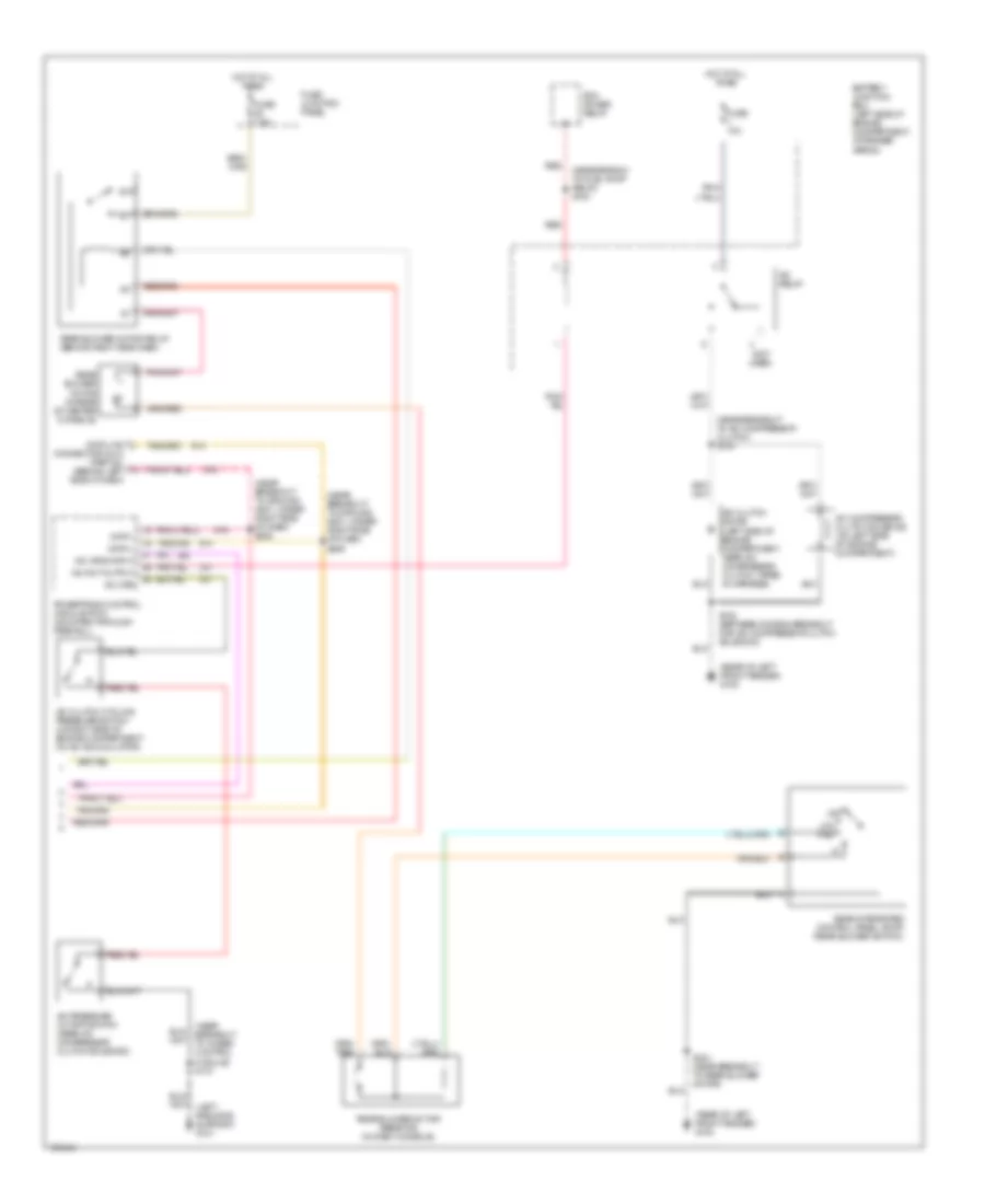
Электросхема кондиционера (1 из 2) для Mercury Mountaineer 1999

Электросхема кондиционера (1 из 2) для Mercury Mountaineer 1999 - Список элементов:
- (near breakout for instrument cluster) s209
- (near breakout to i/p fuse panel) s217
- (near breakout to radio) s200
- (near breakout to rear blower motor relay) s210
- (near breakout to rear window defrost relay) s263
- (not used)
- (rear of left front fender) g100
- (rear of right front fender) g102
- 87a
- A/c demand
- Amb temp sens input
- Ambient air temperature sensor (left front of engine compartment)
- Audio/climate control switch assembly
- Battery
- Battery junction box (left side of engine compartment, at fender apron)
- Blend door 5v+
- Blend door act gnd
- Blend door actuator
- Blend door actuator (behind right side of dash, top of a/c plenum)
- Blend door ref
- Blower motor (right side of engine compartment)
- Blower motor relay
- Blower motor speed controller (near blower motor)
- Blower mtr fback
- Blower mtr rly gnd
- Blr mtr rly out
- C297
- C298
- Clockspring assembly
- Cruise control
- Data (+)
- Data (-)
- Eatc to clockspring
- Electronic automatic temperature control (eatc) module (behind center of dash)
- English/metric in
- Fan
- Fuse 7.5a
- Fuse 2 40a
- Fuse junction panel
- Ground
- Hot at all times
- Hot in run
- Illumination
- In car temp sens
- In-car temperature sensor (behind top center of dash)
- Input ground
- Inst illum
- Interior lights system
- Lamp illum
- Message center
- Nca
- Ohms
- Power
- Rear blr rly gnd
- Red
- Sound systems
- Speed control servo/ amplifier assembly (in right rear engine compartment)
- Speed ctrl out
- Speed ctrl sw gnd
- Sun load sensor (top right side of dash, above glove box)
- Sunload sens input
- Temp
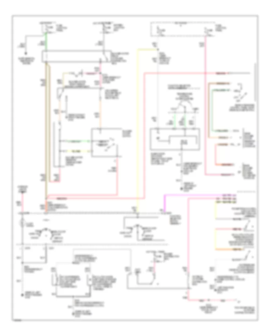
Электросхема кондиционера (2 из 2) для Mercury Mountaineer 1999
Электросхема кондиционера (2 из 2) для Mercury Mountaineer 1999 - Список элементов:
- (left radiator support) g101
- (near branch to fuel pump relay) s123
- (near breakout to 4wabs control module) s137
- (near breakout to a/c compressor clutch) s133
- (near breakout to ground g201, under right side of dash) s205
- (near breakout to ground g201, under right side of dash) s206
- (not used)
- (rear of left front fender) g100
- 87a
- A/c clutch cycling pressure switch (in right side of engine compartment, on a/c accumulator)
- A/c clutch diode (left side of engine compartment, near a/c compressor clutch, taped in harness)
- A/c compressor clutch solenoid (on left side of engine compartment)
- A/c cps
- A/c hpcs input
- A/c pressure cutoff switch (near a/c compressor clutch solenoid)
- A/c relay
- A/c wot output
- Battery junction box (left side of engine compartment, at fender apron)
- Connector (dlc) (partial) (behind left side of dash)
- Data +
- Data -
- Data link
- Fuse 7.5a
- Fuse 10a
- Fuse junction panel
- Hot at all times
- Low med
- Off
- Pcm power relay
- Powertrain control module (pcm) (mounted through firewall)
- Rear blower motor (in rear of center console)
- Rear blower motor relay (behind right side dash)
- Rear blower motor resistor (in dash console)
- Rear integrated control panel (ricp) (rear blower switch)
- Red
- S100 (between diode & breakout for a/c compressor clutch solenoid)
- S231 (near breakout to rear blower motor)
Электросхема кондиционера с ручный управлением для Mercury Mountaineer 1999
Электросхема кондиционера с ручный управлением для Mercury Mountaineer 1999 - Список элементов:
- (left radiator support) g101
- (near breakout for generic electronic module) s229
- (near breakout to 4wabs control module) s159
- (near breakout to a/c compressor clutch solenoid) s133
- (not used)
- (rear of left front fender) g100
- (rear of right front fender) g102
- A/c clutch cycling pressure switch (in right side of engine compartment, on a/c accumulator)
- A/c clutch diode (left side of engine compartment, near a/c compressor clutch, taped in harness)
- A/c compressor clutch solenoid (on left side of engine compartment)
- A/c pressure cutoff switch (near a/c compressor clutch solenoid)
- A/c relay (in power distribution box)
- Battery junction box
- Blend door actuator (behind right side of dash, top of a/c plenum)
- Blower motor (right side of engine compartment)
- Blower motor relay (in power distribution box)
- Blower motor resistor (near blower motor)
- Blower motor switch
- C231
- C276
- Cold
- Def/flr
- Defrost
- Floor
- Function selector switch assembly
- Fuse 7.5a
- Fuse 10a
- Fuse 40a
- Fuse 7.5a
- Fuse junction panel
- High speed blower relay (in auxiliary relay box 2)
- Hot at all times
- Hot in run
- Illumi- nation
- Interior lights system
- Low
- Max a/c
- Med
- Med hi
- Med lo
- Norm a/c
- Off
- Off panel
- Panel
- Panel/floor
- Pcm power relay (in power distribution box)
- Power distribution box
- Powertrain control module (pcm) (mounted through firewall)
- Rear blower motor (in rear of center console)
- Rear blower motor resistor (in dash console)
- Rear integrated control panel (ricp) (rear blower switch)
- Red
- S100 (behind diode & breakout for compressor clutch)
- S123 (near breakout to fuel pump relay)
- S170 (near breakout to blower motor)
- S200 (near breakout to radio)
- Solid state
- Temperature control potentiometer
- To blower motor switch)
- To relay module)
- Warm