СИСТЕМА ПЕРЕДАЧИ ДАННЫХ
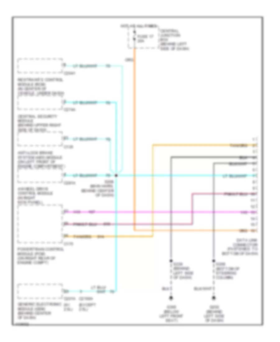
Электросхема компьютерной линии передачи данных CAN для Ford Ranger 2001
Электросхема компьютерной линии передачи данных CAN для Ford Ranger 2001 - Список элементов:
- (except 2.5l)
- (w/ 2.5l)
- 4-wheel drive control module (in right kick panel)
- Anti-lock brake system (abs) module (on left front of engine compartment)
- C135
- C175
- C201a
- C2041
- C2100a
- C274a
- C281a
- Central junction box (behind left side of dash)
- Central security module (behind upper right side of dash)
- Data link connector (fastened to bottom of dash)
- Fuse 17 20a
- G202 (behind left side of dash)
- G300 (below left front seat)
- Generic electronic module (gem) (behind center of dash)
- Hot at all times
- Powertrain control module (pcm) (on right rear of engine compt)
- Restraints control module (rcm) (in center of vehicle, under dash)
- S208 (main harn, behind center of dash)
- S209 (bottom of steering column)
- S236 (behind left side of dash)
 Čeština
 Dansk
Dansk Deutsch
 Ελληνικά
 English
 English
 Español
 Suomi
Suomi Français
 Français
 עברית
עברית Hrvatski
 Magyar
 Italiano
 日本語
日本語 한국어
한국어 Nederlands
 Polski
 Português
 Português
 Română
 Slovenčina
 Slovenščina
 Svenska
 Türkçe
 中文 (中国)
 Русский