СИСТЕМЫ ПОДВЕСКИ
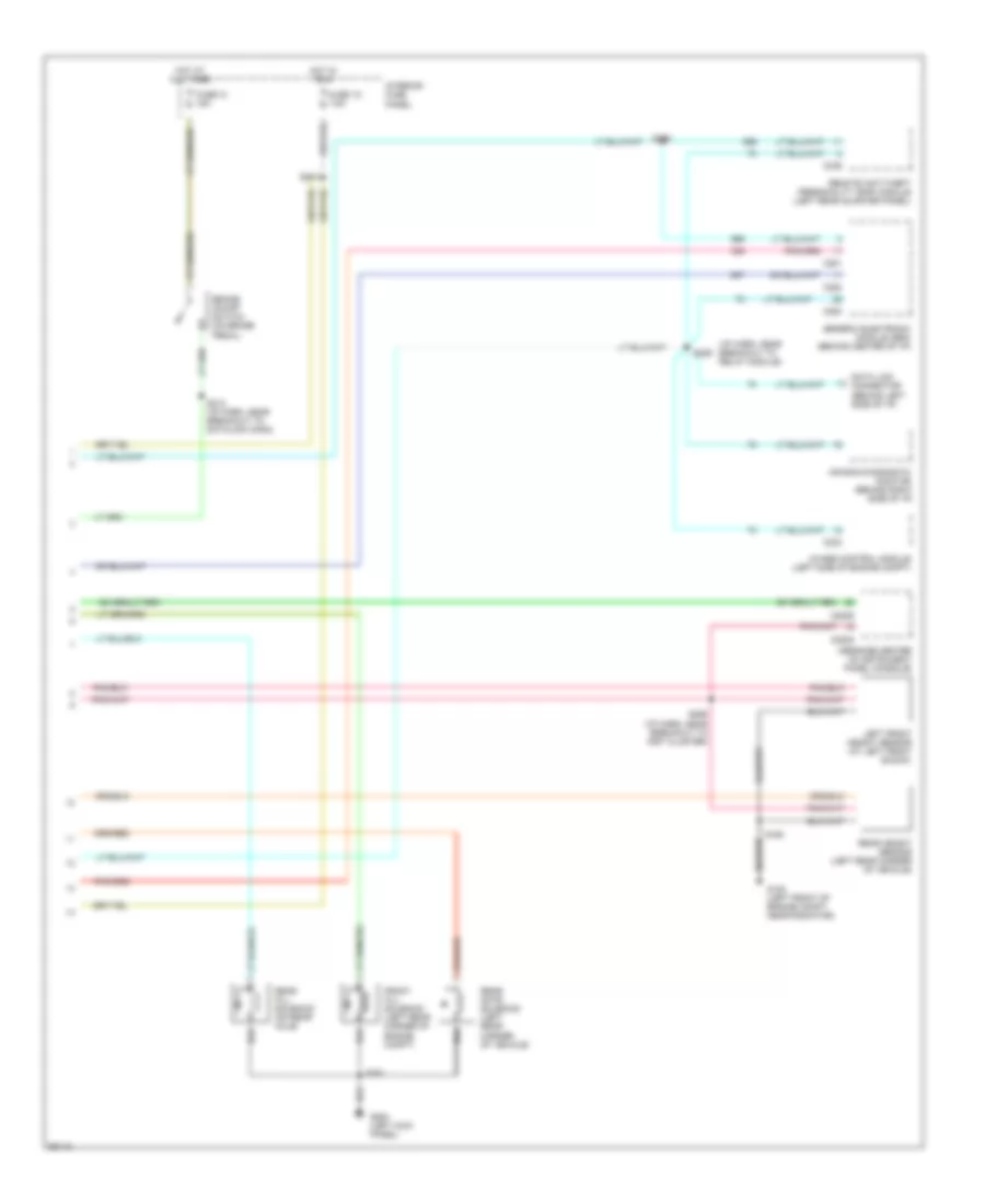
Электросхема электроники подвески (1 из 2) для Ford Explorer 1997

Электросхема электроники подвески (1 из 2) для Ford Explorer 1997 - Список элементов:
- (i/p harn, near breakout to inst cluster)
- (left rear corner of engine compartment, on fender apron)
- 4x4 high sig
- 4x4 low sig
- Arc accel sig
- Arc compr rly
- Arc off/on sw
- Automatic ride control (arc) module (left center of i/p)
- Automatic ride control compressor assembly (at rear of vehicle)
- Automatic ride control off/on switch (rear of vehicle)
- Automatic ride control relay
- Auxiliary relay box #3 (left rear of engine compartment)
- Brake on/off sw
- C2000
- C2001
- Comp vent sol
- Door ajar in
- Engine controls system
- Front fill sol
- Fuse 18 15a
- Fuse 3 50a
- G100 (w/o cellular phone) (left rear corner of engine compt.)
- G104
- G104 (left rear corner of engine compt, at fender apron)
- G105 (right side of engine compt)
- G1oo (left front of engine compt, near radiator)
- G200 (left kick panel)
- G201 (w/ cellular phone) (right side of i/p)
- Gnd
- Height sen power
- Hot at all times
- Iso link
- Left front shock actuator (at left front shock)
- Left rear shock actuator (at left rear shock)
- Lf height sen
- Lf shock actuator
- Lf shock pos in
- Lr shock actuator
- Lr shock pos in
- Nca
- Pcm accel sig
- Pnk
- Power (hot in run)
- Power distribution box
- Powertrain control module (pcm) (right rear of engine compt.)
- Rear fill sol
- Rear gate sol
- Rear height sen
- Red
- Rf shock actuator
- Rf shock pos in
- Right front shock actuator (at right front shock)
- Right rear shock actuator (at right rear shock)
- Rr shock actuator
- Rr shock pos in
- S153
- S157
- S159
- S230
- S232
- S247
- S253
- S351
- Steering sensor
- Steering sensor (in steering column)
- Vehicle speed sensor (on transmission)
- Vss (+)
- Warning sig
Электросхема электроники подвески (2 из 2) для Ford Explorer 1997
Электросхема электроники подвески (2 из 2) для Ford Explorer 1997 - Список элементов:
- (i/p harn, near breakout to relay module)
- 4wabs control module (left side of engine compt)
- Air bag diagnostic monitor (behind right side of i/p)
- Brake on/off switch (on brake pedal)
- C2008
- C2009
- C233
- C280
- C281
- C282
- C336
- Data link connector (behind left side of i/p)
- Front fill solenoid (left rear corner of engine compt)
- Fuse 13 15a
- Fuse 1o 7.5a
- G100 (left front of engine compt, near radiator)
- G200 (left kick panel)
- Generic electronic module (gem) (behind center of i/p)
- Hot at all times
- Hot in run
- Interior fuse panel
- Left front height sensor (at left front shock)
- Message center (in instrument panel console)
- Rear fill solenoid (on rear axle)
- Rear gate solenoid (left rear corner of vehicle)
- Rear height sensor (left rear corner of vehicle)
- Remote anti-theft personality (rap) module (left rear quarter panel)
- S160
- S212 (i/p harn, near breakout to datalink conn)
- S241
- S255
- S256 (i/p harn, near breakout to inst cluster)
- S258
- S351