AIR CONDITIONING
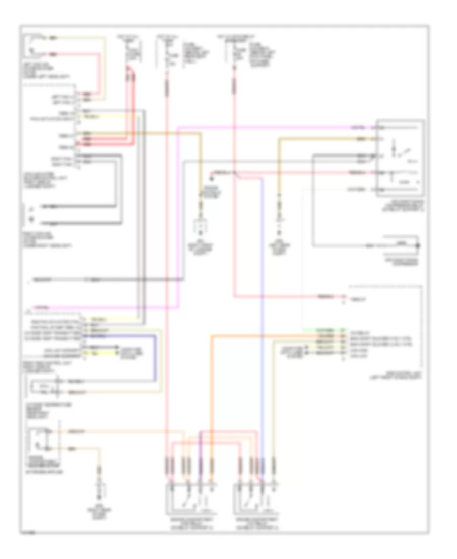
Automatic A/C Wiring Diagram (1 of 2) for Porsche 911 Carrera 4S 2006


List of elements for Automatic A/C Wiring Diagram (1 of 2) for Porsche 911 Carrera 4S 2006:
- +5v/10 ma
- Actuation fan
- Blowing output temper- ature sensor
- Can comfort high
- Can comfort low
- Can drive high
- Can drive low
- Central flap check sig
- Central flap motor
- Circulating air/outside air
- Circulation air/ outside air valve
- Climatronic control unit (behind center of dash)
- Close outside air
- Compressor voltage
- Computer data lines system
- Cool
- Cooling water pressure sensor
- Current distributor
- Defrost
- Fan
- Fan return
- Fan return (+)
- Final stage
- Footwell
- Footwell/defrost
- Footwell/defrost flap
- Footwell/defrost signal
- Fuse b10 25a
- Fuse c2 7.5a
- Fuse f6 80a
- Fuse holder b (behind left kick panel, on fuses support)
- Fuse holder c (behind left kick panel, on fuses support)
- Gp5 (right side of support frame)
- Heater ctrl rly
- Heater relay (on relay support 1)
- Hot
- Hot at all times
- Hot in run or start
- Intake air temper- ature sensor
- Middle level
- Output sensor footwell
- Output temp sensor
- Pas control unit (behind left side of dash)
- Pressure sens
- Red
- Sensor ground
- Sun sens
- Sun sensor (under to center of dash)
- Temperature flap
- Temperature flap signal
- Term 15
- Term 30
- Term 31
- Up outside air
Automatic A/C Wiring Diagram (2 of 2) for Porsche 911 Carrera 4S 2006
List of elements for Automatic A/C Wiring Diagram (2 of 2) for Porsche 911 Carrera 4S 2006:
- A/c relay
- Air conditioning compressor
- Air conditioning compressor relay (on relay support 2)
- Can high
- Can high comfort
- Can low
- Can low comfort
- Computer data lines system
- Cooling water blower control unit (right side of luggage compt)
- Dme control unit (left front of eng compt)
- Eng compt blower hi rly ctrl
- Eng compt blower lo rly ctrl
- Engine compartment blower motor
- Engine compartment high relay (on relay support 2)
- Engine compartment low relay (on relay support 2)
- Engine controls system
- Extended spoiler
- Fan final stage term 15
- Front end control unit (right side of luggage compt)
- Fuse 15a
- Fuse d5 40a
- Fuse holder d (behind left kick panel, on fuses support)
- Fuse holder f (behind left rear seat well)
- Gp1 (right front of luggage compt)
- Gp8 (left rear of eng compt)
- Gp9 (right rear of eng compt)
- Hot at all times
- Hot w/ mfi-di relay energized
- Left cooling water blower motor (under left headlight)
- Left fan (+)
- Left fan (-)
- Maxi fuse 80a
- Nca
- Outside temp transmitter
- Outside temperature sensor (near right headlight)
- Pwm actuation input
- Rad fan actuator ctrl
- Red
- Right cooling water blower motor (under right headlight)
- Right fan +
- Right fan -
- Term 15
- Term 30
- Term 31
- Term 87

 English