СИСТЕМА КОНДИЦИОНЕРА
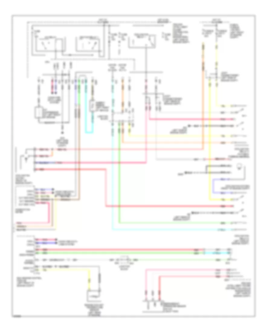
Электросхема кондиционера (1 из 2) для Nissan Maxima SV 2009

Электросхема кондиционера (1 из 2) для Nissan Maxima SV 2009 - Список элементов:
Электросхема кондиционера (2 из 2) для Nissan Maxima SV 2009
Электросхема кондиционера (2 из 2) для Nissan Maxima SV 2009 - Список элементов: