СИСТЕМА ПЕРЕДАЧИ ДАННЫХ
2.0L
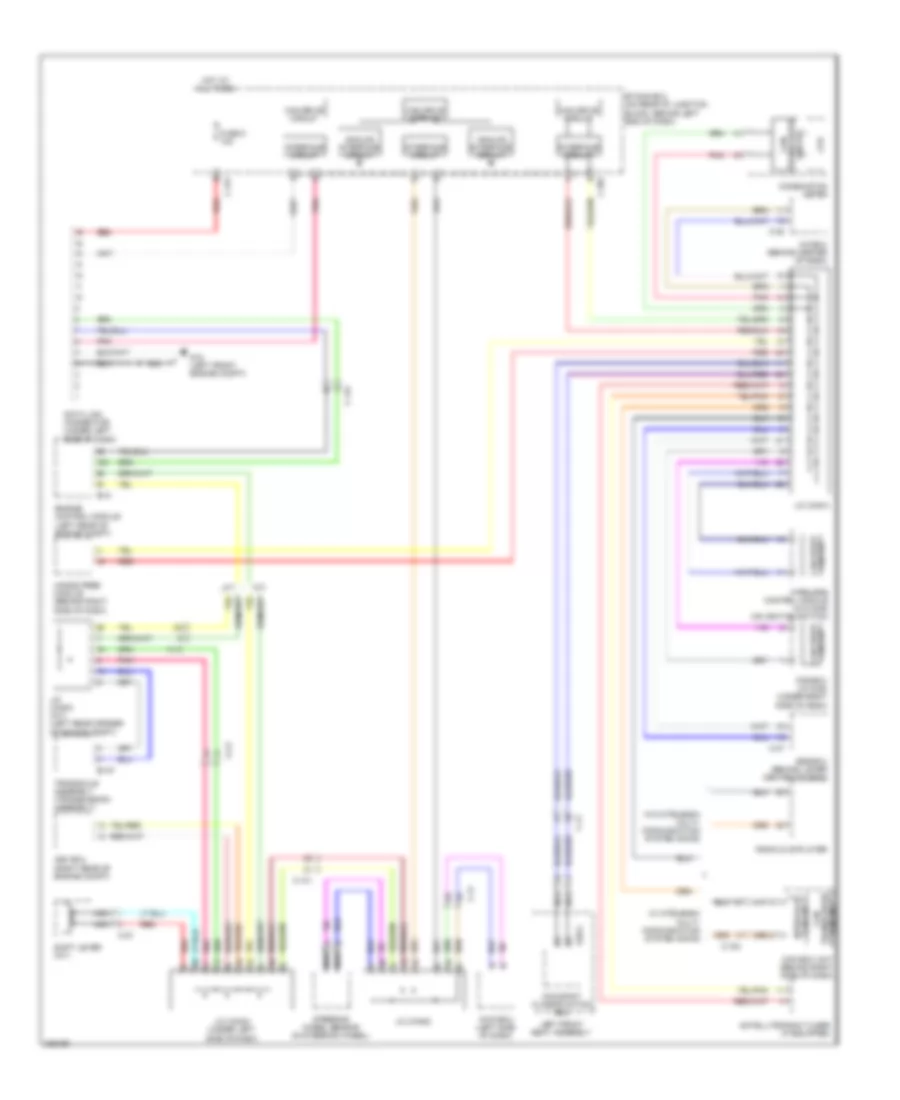
2.0L, Электросхема линии передачи данных CAN для Mitsubishi Lancer Evolution GSR 2010
 https://portal-diagnostov.com/license.html
Automotive Electricians Portal FZCO
Automotive Electricians Portal FZCO
https://portal-diagnostov.com/license.html
https://portal-diagnostov.com/license.html
Automotive Electricians Portal FZCO
Automotive Electricians Portal FZCO
2.0L, Электросхема линии передачи данных CAN для Mitsubishi Lancer Evolution GSR 2010 - Список элементов:
- (not used)
- A/c ecu (w/ air conditioning) heater control unit (w/o air conditioning) (behind center of dash)
- Analog interface circuit
- Asc ecu (right rear of engine compt)
- B-109
- C-105
- C-122
- C-128
- C-133
- C-20
- C-301
- C-317
- C-35
- C-41
- C-48
- C-51
- Can box unit (behind right side of dash)
- Can drive circuit
- Can transceiver circuit
- Circuit can drive
- Combination meter
- Cpu
- D35-2
- Data link connector (under left side of dash)
- Engine control module (left rear of engine compt)
- Etacs ecu (on rear of junction block, behind left end of dash)
- Fuse 5 10a
- G14 (behind left kick panel)
- Hands free module (behind right side of dash)
- Hot at all times
- Interface circuit
- J/c (can1)
- J/c (can2)
- J/c (can3) (under left side of dash)
- Kos ecu (w/ kos) (under right side of dash)
- Nca
- Occupant classification ecu
- Pnk
- Radio & cd player/ cd changer
- Red
- Right front seat assembly
- Satellite radio tuner (if equipped)
- Srs ecu (behind lower center of dash)
- Steering wheel sensor (in steering wheel)
- Transaxle control module (behind left side of dash)
- W/ air conditioning
- W/ mitsubishi multi- communication system (mmcs)
- W/o air conditioning
- W/o mitsubishi multi- communication system (mmcs)
- Wireless control module (w/o kos) (on ignition switch)
2.0L ТУРБО
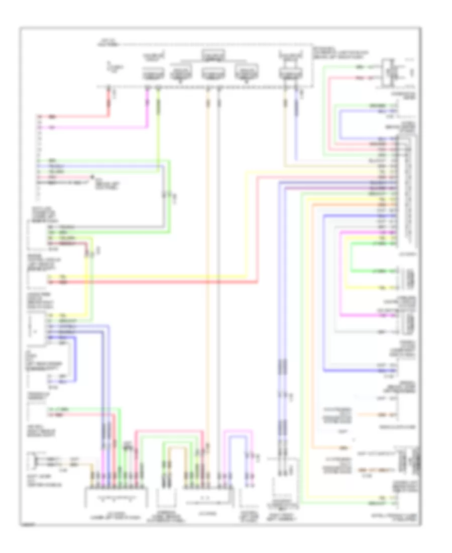
2.0L турбо, Электросхема линии передачи данных CAN, эволюция для Mitsubishi Lancer Evolution GSR 2010
2.0L турбо, Электросхема линии передачи данных CAN, эволюция для Mitsubishi Lancer Evolution GSR 2010 - Список элементов:
- A-13
- A/c ecu (behind center of dash)
- A/t
- Analog interface circuit
- Asc ecu (right rear of engine compt)
- Awc-ecu (left side of dash)
- B-10
- B-107
- C-108
- C-131
- C-22
- C-27
- C-301
- C-317
- C-37
- C-41
- Can box unit (behind right side of dash)
- Can drive circuit
- Can transceiver circuit
- Circuit
- Circuit can drive
- Combination meter
- Cpu
- D39-2
- Data link connector (under left side of dash)
- Engine control module (left rear of engine compt)
- Etacs ecu (on rear of junction block, behind left end of dash)
- Fuse 5 10a
- G18 (left front engine compt)
- Hands free module (behind right side of dash)
- Hot at all times
- Interface circuit
- J/c (can1)
- J/c (can2)
- J/c (can3) (under left side of dash)
- J/c (can4) (a/t) (left rear corner of engine compt)
- Kos ecu (w/ kos) (under right side of dash)
- Left front seat assembly
- M/t
- Nca
- Occupant classification ecu
- Pnk
- Radio & cd player
- Red
- Satellite radio tuner (if equipped)
- Shift lever (a/t)
- Srs ecu (behind lower center of dash)
- Steering wheel sensor (in steering wheel)
- Transaxle assembly (transmission assembly)
- Transceiver can
- W/ mitsubishi multi- communication system (mmcs)
- W/o mitsubishi multi- communication system (mmcs)
- Wireless control module (w/o kos) (on ignition switch)
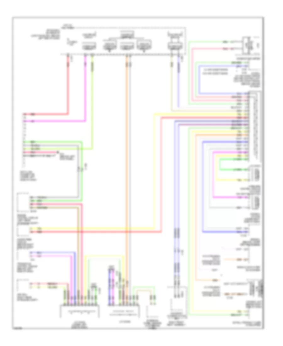
2.0L турбо, Электросхема линии передачи данных CAN, кроме эволюции для Mitsubishi Lancer Evolution GSR 2010
2.0L турбо, Электросхема линии передачи данных CAN, кроме эволюции для Mitsubishi Lancer Evolution GSR 2010 - Список элементов:
- (not used)
- A-54
- A/c ecu (behind center of dash)
- Analog interface circuit
- Asc ecu (right rear of engine compt)
- Awc-ecu (left side of dash)
- B-109
- B-120
- C-105
- C-122
- C-128
- C-133
- C-20
- C-301
- C-317
- C-35
- C-49
- Can box unit (behind right side of dash)
- Can drive circuit
- Can transceiver circuit
- Circuit can drive
- Combination meter
- Cpu
- D35-2
- Data link connector (under left side of dash)
- Engine control module (left rear of engine compt)
- Etacs ecu (on rear of junction block, behind left end of dash)
- Fuse 5 10a
- G14 (behind left kick panel)
- Hands free module (behind right side of dash)
- Hot at all times
- Interface circuit
- J/c (can1)
- J/c (can2)
- J/c (can3) (under left side of dash)
- J/c (can4) (a/t) (left rear corner of engine compt)
- Kos ecu (w/ kos) (under right side of dash)
- Nca
- Occupant classification ecu
- Pnk
- Radio & cd player
- Red
- Right front seat assembly
- Satellite radio tuner (if equipped)
- Shift lever (a/t) (center console)
- Srs ecu (behind lower center of dash)
- Steering wheel sensor (in steering wheel)
- Transaxle assembly
- W/ mitsubishi multi- communication system (mmcs)
- W/o mitsubishi multi- communication system (mmcs)
- Wireless control module (w/o kos) (on ignition switch)
2.4L
2.4L, Электросхема линии передачи данных CAN для Mitsubishi Lancer Evolution GSR 2010
2.4L, Электросхема линии передачи данных CAN для Mitsubishi Lancer Evolution GSR 2010 - Список элементов:
- (not used)
- A/c ecu (w/ air conditioning) heater control unit (w/o air conditioning) (behind center of dash)
- Analog interface circuit
- Asc ecu (right rear of engine compt)
- B-109
- C-105
- C-122
- C-128
- C-133
- C-20
- C-301
- C-317
- C-35
- C-41
- C-48
- C-51
- Can box unit (behind right side of dash)
- Can drive circuit
- Can transceiver circuit
- Circuit can drive
- Combination meter
- Cpu
- D35-2
- Data link connector (under left side of dash)
- Engine control module (left rear of engine compt)
- Etacs ecu (on rear of junction block, behind left end of dash)
- Fuse 5 10a
- G14 (behind left kick panel)
- Hands free module (behind right side of dash)
- Hot at all times
- Interface circuit
- J/c (can1)
- J/c (can2)
- J/c (can3) (under left side of dash)
- Kos ecu (w/ kos) (under right side of dash)
- Nca
- Occupant classification ecu
- Pnk
- Radio & cd player/ cd changer
- Red
- Right front seat assembly
- Satellite radio tuner (if equipped)
- Srs ecu (behind lower center of dash)
- Steering wheel sensor (in steering wheel)
- Transaxle control module (behind left side of dash)
- W/ air conditioning
- W/ mitsubishi multi- communication system (mmcs)
- W/o air conditioning
- W/o mitsubishi multi- communication system (mmcs)
- Wireless control module (w/o kos) (on ignition switch)

 Čeština
 Dansk
Dansk Deutsch
 Ελληνικά
 English
 English
 Español
 Suomi
Suomi Français
 Français
 עברית
עברית Hrvatski
 Magyar
 Italiano
 日本語
日本語 한국어
한국어 Nederlands
 Polski
 Português
 Português
 Română
 Slovenčina
 Slovenščina
 Svenska
 Türkçe
 中文 (中国)