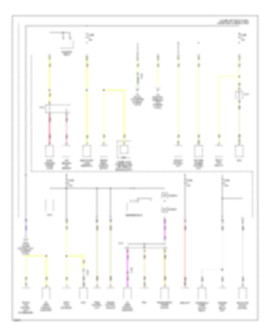
БЛОК ПРЕДОХРАНИТЕЛЕЙ И РЕЛЕ
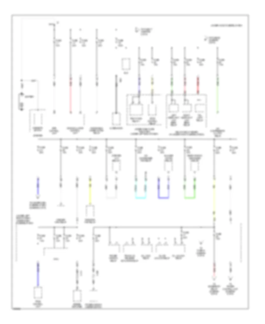
Электросхема блока предохранителей и реле, кроме гибрида (1 из 6) для Acura ILX 2014
Электросхема блока предохранителей и реле, кроме гибрида (1 из 6) для Acura ILX 2014 - Список элементов:
- (under left end of dash) under-dash fuse/relay box
- A/c compressor clutch relay
- A/c condenser fan relay
- Alternator
- Battery
- Blower motor relay
- C109
- C111
- D/l dr unlock relay
- D/l lock relay
- D/l unlock relay
- D12
- Eld
- Eps control unit
- Etcs control relay
- Fuse 1-1 70a
- Fuse 1-3 30a
- Fuse 1-4 30a
- Fuse 1-5 30a
- Fuse 1-6 100a
- Fuse 10a
- Fuse 15a
- Fuse 2-1 50a
- Fuse 2-10 20a
- Fuse 2-11 20a
- Fuse 2-2 60a
- Fuse 2-3 60a
- Fuse 2-4 30a
- Fuse 2-5 30a
- Fuse 2-6 30a
- Fuse 2-8 40a
- Fuse 20a
- Fuse 7.5a
- Left headlight low beam relay
- Magnetic switch
- Micu
- Pgm-fi main relay 1
- Power window master switch
- Power window relay
- Radiator fan relay
- Rear window defogger relay
- Red
- Relay circuit board (in under-hood fuse/relay box)
- Right headlight low beam relay
- Starter
- Starter cut relay 1
- Stereo amplifier
- T101
- Tail light relay
- To accessory relay (diagram 5 of 6)
- To fuse 17 (diagram 2 of 6)
- To fuse 29 (diagram 2 of 6)
- To fuse 44 (diagram 5 of 6)
- To power control unit (diagram 6 of 6)
- To under-dash fuse/relay box (diagram 3 of 6)
- Tpms control unit
- Trunk lid release actuator relay
- Under-dash fuse/ relay box (under left end of dash)
- Under-hood fuse/relay box
- Vsa modulator control unit
- Washer main relay
- Windshield wiper motor relay
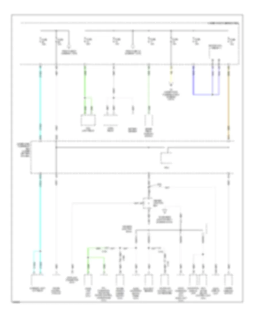
Электросхема блока предохранителей и реле, кроме гибрида (2 из 6) для Acura ILX 2014
Электросхема блока предохранителей и реле, кроме гибрида (2 из 6) для Acura ILX 2014 - Список элементов:
- 2.4l
- A16
- Acuralink control unit (xm receiver)
- Anc/ active sound control unit (2.4l)
- Audio display unit
- Audio navigation switch panel (2.0l)
- Audio navigation unit (2.0l) audio unit (2.4l)
- Battery sensor
- Brake pedal position switch
- C102
- C108
- C109
- C119
- Center junction box
- D11
- D18
- D28
- Data link connector (dlc)
- Driver's junction box 2
- Fog light relay
- From fuse 1-6 (diagram 1 of 6)
- From fuse 27 (diagram 1 of 6)
- Fuse 10a
- Fuse 15a
- Fuse 20a
- Fuse 7.5a
- Gauge control module
- Hazard warning switch
- Hfl- navigation- anc/active sound control microphone (2.0l)
- Home link unit (2.0l)
- Horn relay
- Ignition coil relay
- Interior light cut relay
- Micu
- N13
- Navigation display unit
- Power window master switch (2.0l)
- Q16
- Sunlight sensor
- To driver's junction box 1 (diagram 6 of 6)
- To under-hood fuse/relay box (diagram 3 of 6)
- Under-dash fuse/relay box (under left end of dash)
- Under-hood fuse/relay box
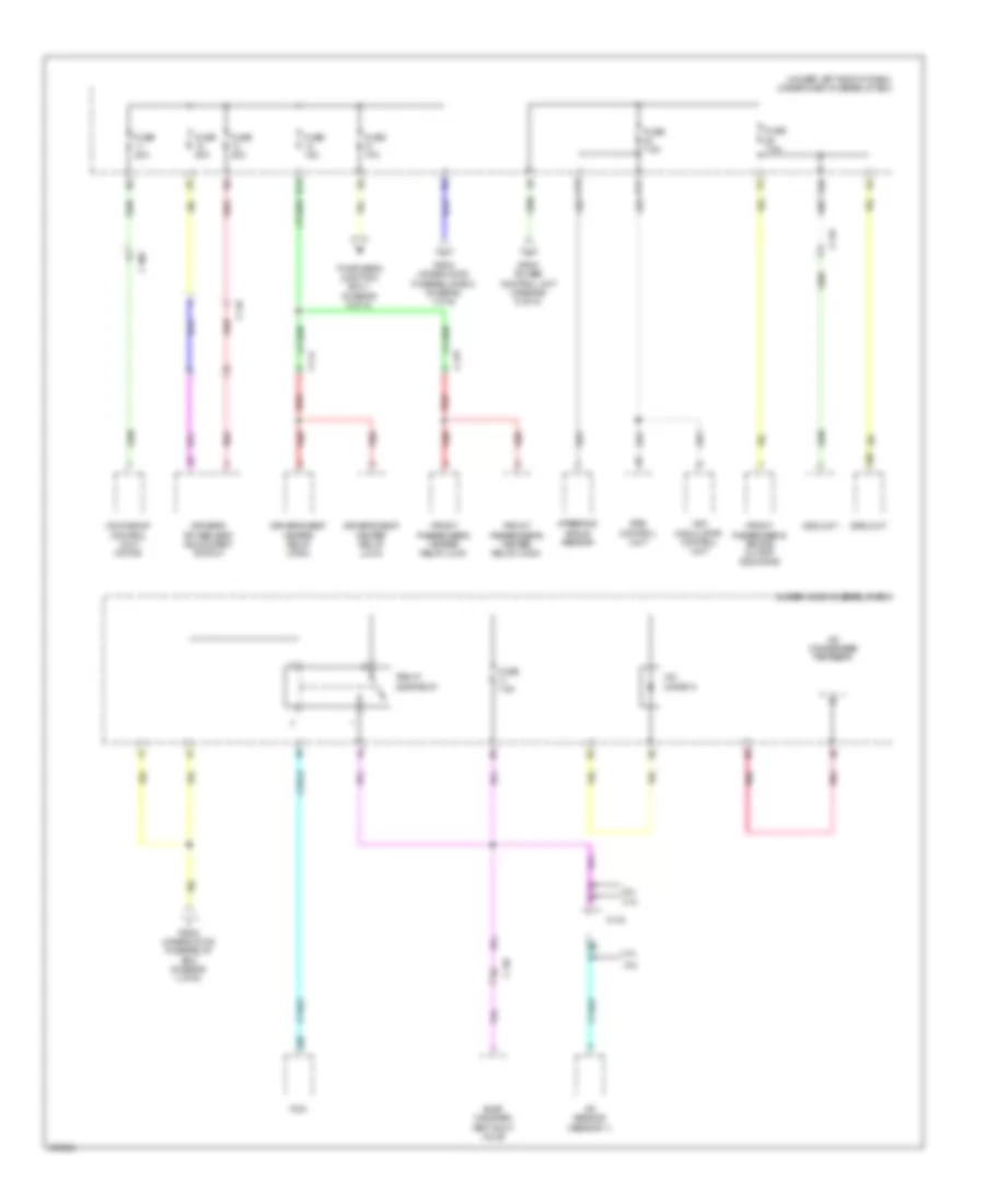
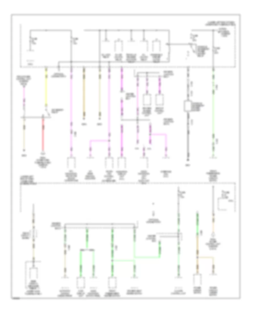
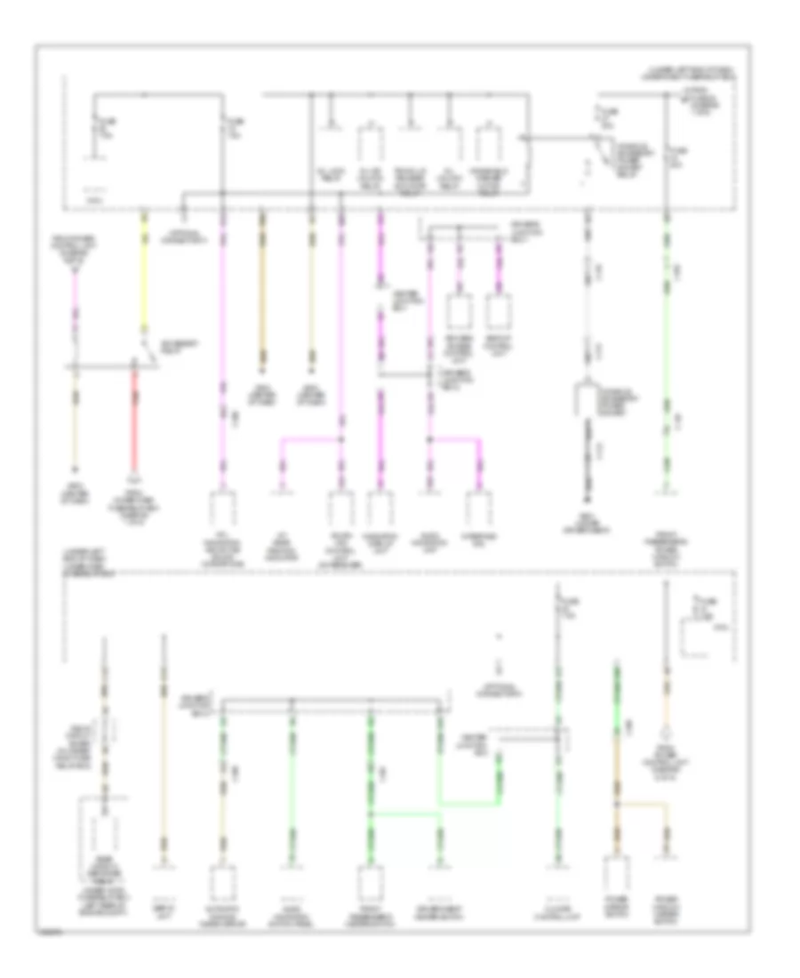
Электросхема блока предохранителей и реле, кроме гибрида (3 из 6) для Acura ILX 2014
Электросхема блока предохранителей и реле, кроме гибрида (3 из 6) для Acura ILX 2014 - Список элементов:
- (under left end of dash) under-dash fuse/relay box
- 2.0l
- 2.4l
- A/c condenser fan relay
- A/c diode a
- A/f sensor (sensor 1)
- A20
- A39
- B13
- B30
- C108
- C110
- C114
- C118
- C120
- C133
- D31
- Driver's power seat adjustment switch
- Driver's seat heater relay (high)
- Driver's seat heater relay (low)
- Eps control unit
- Evap canister vent shut valve
- From power control unit (diagram 6 of 6)
- From under-hood fuse/relay box (diagram 1 of 6)
- From under-hood fuse/relay box (diagram 2 of 6)
- Front passenger's air bag cutoff indicator
- Front passenger's heater relay (high)
- Front passenger's heater relay (low)
- Fuse 10a
- Fuse 15a
- Fuse 20a
- Fuse 7.5a
- Moonroof control unit/ motor
- Ods unit
- P15
- Pcm
- Pgm-fi sub relay
- Pnk
- Red
- Srs unit
- Steering angle sensor
- To driver's junction box 1 (diagram 6 of 6)
- Under-hood fuse/relay box
- Vsa modulator control unit
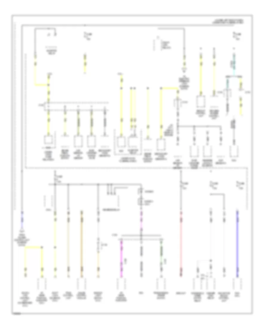
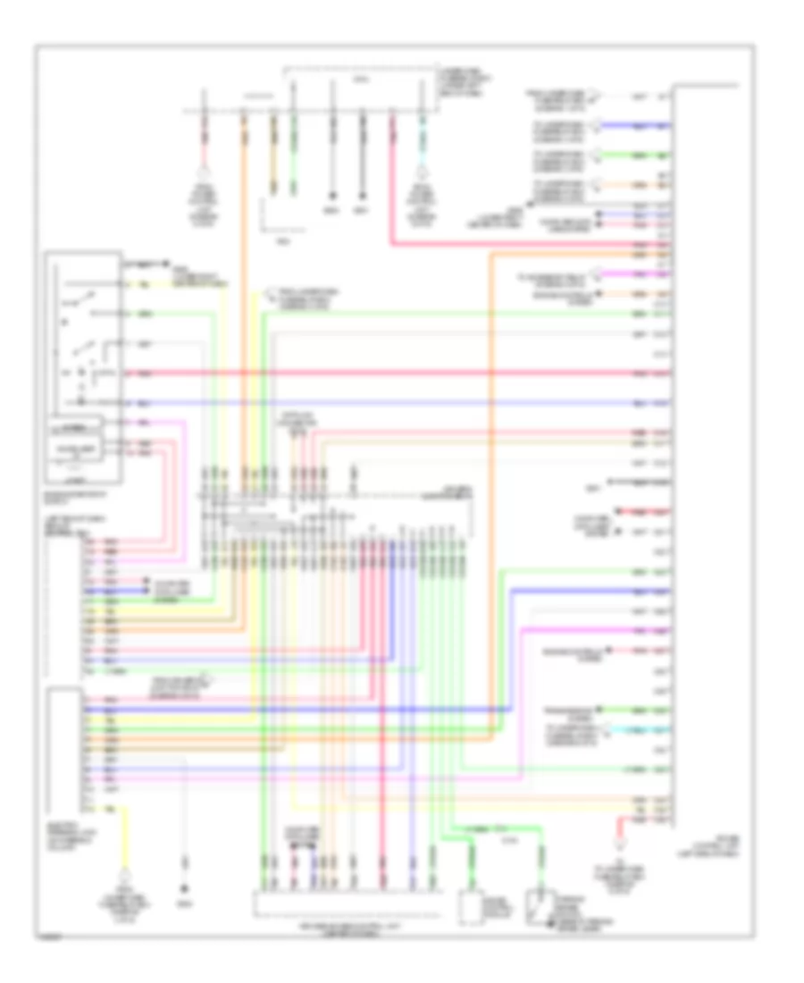
Электросхема блока предохранителей и реле, кроме гибрида (4 из 6) для Acura ILX 2014
Электросхема блока предохранителей и реле, кроме гибрида (4 из 6) для Acura ILX 2014 - Список элементов:
- (under left end of dash) under-dash fuse/relay box
- 2.0l
- 2.4l
- A/t gear position indicator
- A/t gear position indicator (2.0l)
- A15
- A38
- Acura link control unit (xm receiver) (2.0l)
- Anc/active sound control unit
- B25
- B28
- B32
- Backup control unit
- Backup light switch (2.4l)
- Brake pedal position switch
- C10
- C120
- C127
- C13
- C130
- C133
- C28
- C36
- Cmp sensor a
- D10
- D24
- Diode c (2.0l)
- Diode d
- Eld
- Evap canister purge valve
- From power control unit (diagram 6 of 6)
- Fuse 10a
- Fuse 15a
- Fuse 7.5a
- Gauge control module
- Inhibitor relay
- J/c c011 (right rear of engine)
- Keyless access control unit
- Maf sensor/ iat sensor
- Micu
- P18
- Pcm
- Pcm (2.0l)
- Pgm-fi main relay 2
- Q11
- Red
- Reverse lockout solenoid
- Reverse relay
- Secondary ho2s (sensor 2)
- Shift lock solenoid (2.0l)
- Srs unit
- Tan
- To electric steering lock (diagram 6 of 6)
- Tpms control unit
- Transmission range switch
- Under- hood fuse/ relay box
- Under-hood fuse/relay box
- Washer main relay
- Windshield wiper motor relay
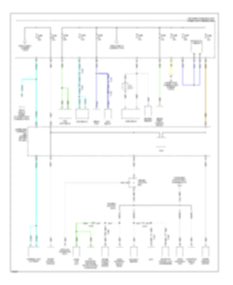
Электросхема блока предохранителей и реле, кроме гибрида (5 из 6) для Acura ILX 2014
Электросхема блока предохранителей и реле, кроме гибрида (5 из 6) для Acura ILX 2014 - Список элементов:
- (optional connector f)
- (under left end of dash) under-dash fuse/relay box
- 2.0l
- 2.4l
- A/t gear position indicator
- A14
- A24
- Accessory relay
- Acura link control unit (xm receiver)
- Audio navigation switch panel
- Audio navigation unit (2.0l) audio unit (2.4l)
- Automatic dimming inside mirror
- B26
- Backup control unit
- C104
- C107
- C108
- C109
- C110
- C113
- C125
- C17
- Center junction box
- Climate control unit
- Console accessory power socket
- Console accessory power socket relay
- D/l dr unlock relay
- D/l lock relay
- D/l unlock relay
- Driver's junction box 1
- Driver's junction box 2
- Driver's seat heater switch
- From fuse 25 (diagram 1 of 6)
- From power control unit (diagram 6 of 6)
- From under-dash fuse/relay box (diagram 1 of 6)
- Front passenger's heater switch
- Front passenger's power window switch
- Fuse 20a
- Fuse 7.5a
- G503
- G601
- H10
- Hfl- navigation- anc/active sound microphone
- Hvac display unit
- Interface dial (2.0l)
- Keyless access control unit
- Micu
- Navigation display unit (2.0l)
- P14
- P20
- Power mirror switch
- Power window master switch
- Rear window defogger relay
- Red
- Relay circuit board
- S10
- Trunk lid release actuator relay
- Under-hood fuse/relay box
- Windshield washer motor relay
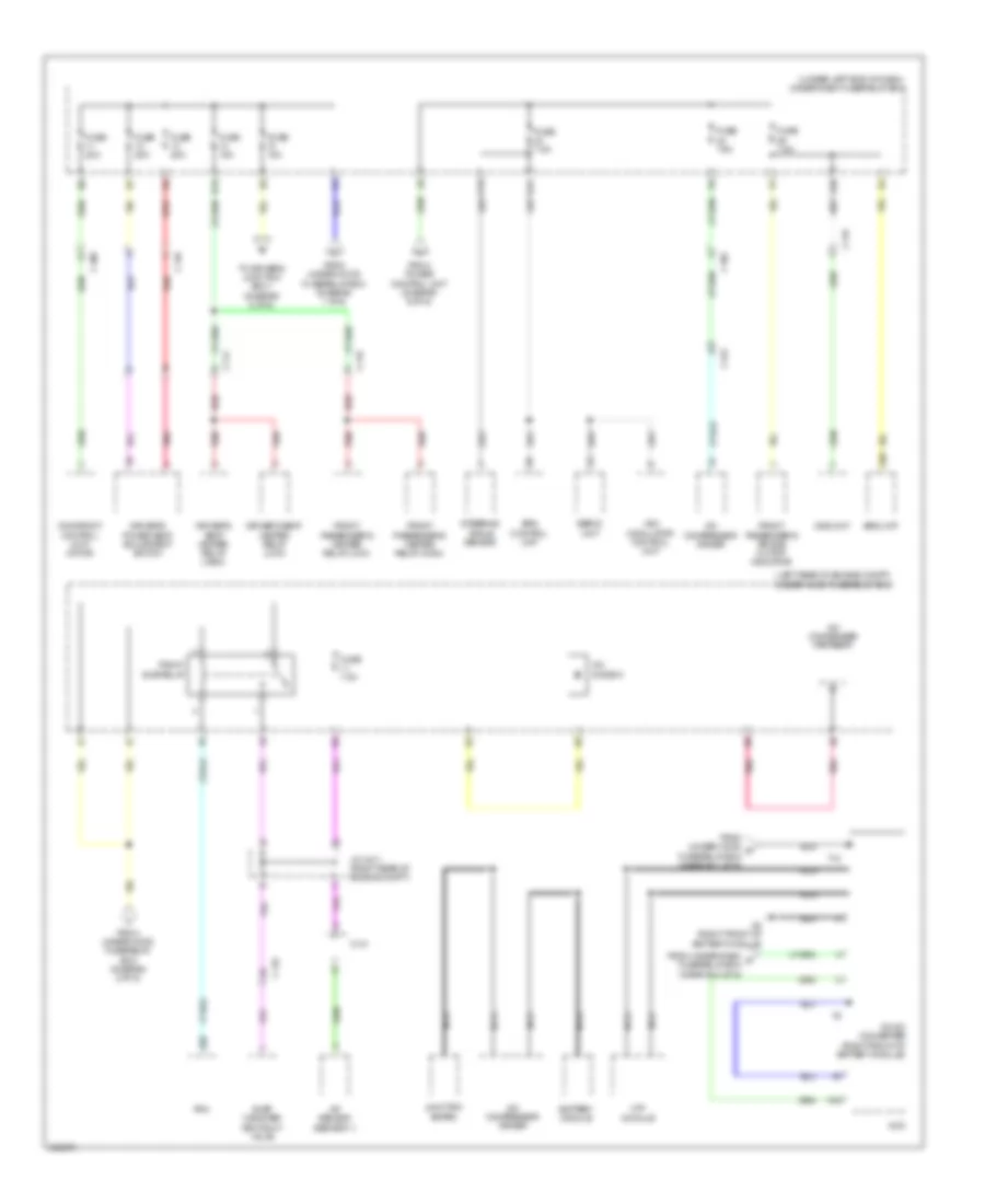
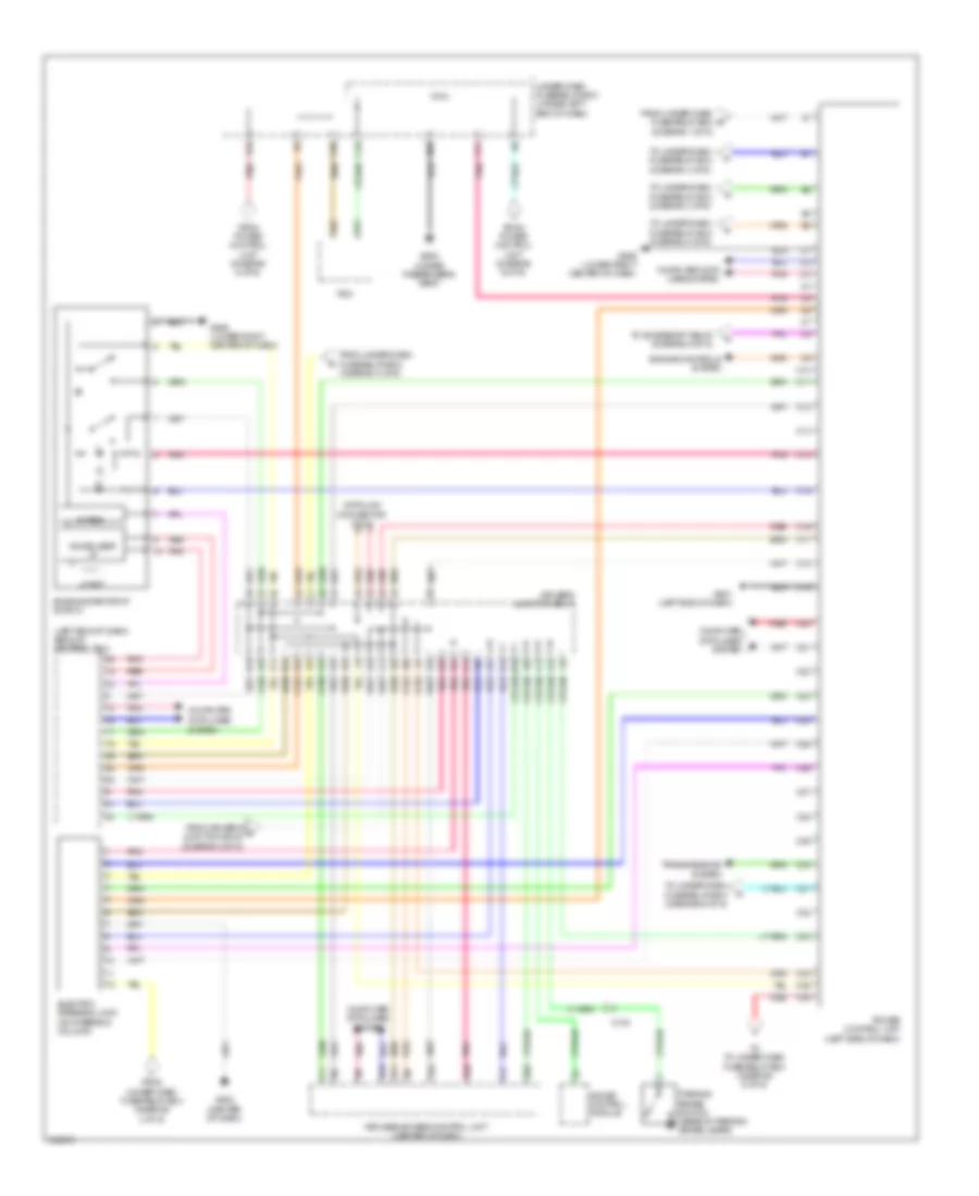
Электросхема блока предохранителей и реле, кроме гибрида (6 из 6) для Acura ILX 2014
Электросхема блока предохранителей и реле, кроме гибрида (6 из 6) для Acura ILX 2014 - Список элементов:
- (diagram 1 of 6)
- (left end of dash) backup control unit
- 5v reg
- A13
- A28
- A42
- B10
- B11
- B16
- B25
- B32
- C10
- C103
- C11
- C12
- C13
- C14
- C15
- C16
- C17
- C18
- C19
- C20
- C21
- C22
- C23
- C24
- C25
- C26
- C27
- C28
- C29
- C30
- C31
- C32
- C33
- C34
- C35
- C36
- Computer data lines system
- Data link connector (dlc)
- Driver's junction box 1
- Electric steering lock (on steering column)
- Engine controls system
- Engine start/stop switch
- From driver's o junction box 2 (diagram 2 of 6)
- From power control unit (diagram 6 of 6)
- From under-dash fuse/relay box (diagram 3 of 6)
- From under-dash fuse/relay box (diagram 4 of 6)
- From under-dash fuse/relay box e
- G501
- G502
- G506 (lower right center of dash)
- G602
- Gauge control module
- H10
- Immobilizer i/f
- Keyless access control unit (center of dash)
- Lf ant
- Micu
- P11
- P19
- Parking brake switch (base of parking brake lever)
- Pcm
- Pnk
- Power control unit (left side of dash)
- Red
- To accessory relay (diagram 5 of 6)
- To to under-dash fuse/relay box (diagram 6 of 6)
- To under-dash fuse/relay box (diagram 3 of 6)
- To under-dash fuse/relay box (diagram 4 of 6)
- To under-dash fuse/relay box (diagram 5 of 6)
- To under-dash fuse/relay box (diagram 6 of 6)
- Transmissions system
- Under-dash fuse/relay box (under left end of dash)
Электросхема блока предохранителей и реле, гибрид (1 из 6) для Acura ILX 2014
Электросхема блока предохранителей и реле, гибрид (1 из 6) для Acura ILX 2014 - Список элементов:
- (left rear of engine compt) under-hood fuse/relay box
- (under left end of dash) under-dash fuse/relay box
- A/c compressor clutch relay
- A/c condenser fan relay
- Battery
- Blower motor relay
- C109
- C111
- D/l dr unlock relay
- D/l lock relay
- D/l unlock relay
- D12
- Eld
- Eps control unit
- Etcs control relay
- Fuse 1-1 70a
- Fuse 1-2 40a
- Fuse 1-3 30a
- Fuse 1-4 30a
- Fuse 1-5 30a
- Fuse 1-6 100a
- Fuse 10a
- Fuse 15a
- Fuse 2-1 50a
- Fuse 2-10 20a
- Fuse 2-11 20a
- Fuse 2-2 60a
- Fuse 2-3 60a
- Fuse 2-4 30a
- Fuse 2-5 30a
- Fuse 2-6 30a
- Fuse 2-8 40a
- Fuse 20a
- Fuse 7.5a
- G5 (left rear of engine compt)
- Left headlight low beam relay
- Magnetic switch
- Micu
- Pgm-fi main relay 1
- Power window master switch
- Power window relay
- Radiator fan relay
- Rear window defogger relay
- Red
- Relay circuit board (in under-hood fuse/relay box)
- Right headlight low beam relay
- Servo unit
- Starter
- Starter cut relay 1
- Stereo amplifier
- T101
- Tail light relay
- To accessory relay (diagram 5 of 6)
- To dc-dc converter (diagram 3 of 6)
- To fuse 19 (diagram 2 of 6)
- To fuse 28 (diagram 2 of 6)
- To fuse 44 (diagram 5 of 6)
- To power control unit (diagram 6 of 6)
- To under-dash fuse/relay box (diagram 3 of 6)
- Tpms control unit
- Trunk lid release actuator relay
- Under-dash fuse/ relay box (under left end of dash)
- Vsa modulator control unit
- Washer main relay
- Windshield wiper motor relay
Электросхема блока предохранителей и реле, гибрид (2 из 6) для Acura ILX 2014
Электросхема блока предохранителей и реле, гибрид (2 из 6) для Acura ILX 2014 - Список элементов:
- (left rear of engine compt) under-hood fuse/relay box
- A14
- A16
- Acuralink control unit (xm receiver)
- Audio navigation switch panel
- Audio navigation unit
- Battery sensor
- Brake pedal position switch
- C104
- C108
- C109
- C112
- C120
- C122
- C123
- Center junction box
- D11
- D18
- D28
- Data link connector (dlc)
- Driver's junction box 2
- Fog light relay
- From fuse 1-6 (diagram 1 of 6)
- From fuse 27 (diagram 1 of 6)
- Fuse 10a
- Fuse 15a
- Fuse 20a
- Fuse 7.5a
- Gauge control module
- Hazard warning switch
- Hfl- navigation- anc/active sound control microphone
- Home- link unit
- Horn relay
- Ignition coil relay
- Interior light cut relay
- J/c c011
- Mcm
- Mcm relay 1
- Mcm relay 2
- Micu
- N13
- Navigation display unit
- Power window master switch
- Q16
- Relay circuit board (in under-hood fuse/relay box)
- Servo unit
- Sunlight sensor
- To driver's junction box 1 (diagram 6 of 6)
- To under-hood fuse/relay box (diagram 3 of 6)
- Under-dash fuse/relay box (under left end of dash)
Электросхема блока предохранителей и реле, гибрид (3 из 6) для Acura ILX 2014
Электросхема блока предохранителей и реле, гибрид (3 из 6) для Acura ILX 2014 - Список элементов:
- (left rear of engine compt) under-hood fuse/relay box
- (under left end of dash) under-dash fuse/relay box
- A/c compressor driver
- A/c condenser fan relay
- A/c diode a
- A/f sensor (sensor 1)
- A19
- A20
- A39
- B13
- B30
- Battery module
- C102
- C108
- C110
- C114
- C119
- C122
- C123
- C131
- D31
- Dc-dc converter (right front of battery module)
- Driver's power seat adjustment switch
- Driver's seat heater relay (high)
- Driver's seat heater relay (low)
- Eps control unit
- Evap canister vent shut valve
- From power control unit (diagram 6 of 6)
- From under-dash s fuse/relay box (diagram 4 of 6)
- From under-hood fuse/relay box (diagram 1 of 6)
- From under-hood fuse/relay box (diagram 2 of 6)
- From under-hood r fuse/relay box (diagram 1 of 6)
- Front passenger's air bag cutoff indicator
- Front passenger's heater relay (high)
- Front passenger's heater relay (low)
- Fuse 10a
- Fuse 15a
- Fuse 20a
- Fuse 7.5a
- G4 (right front of battery module)
- J/c c011 (right rear of engine compt)
- Junction board
- Mcm
- Moonroof control unit/ motor
- Mpi module
- Nca
- Ods unit
- P15
- Pcm
- Pgm-fi sub relay
- Pnk
- Red
- Servo unit
- Srs unit
- Steering angle sensor
- T10
- To driver's junction box 1 (diagram 6 of 6)
- Vsa modulator control unit
Электросхема блока предохранителей и реле, гибрид (4 из 6) для Acura ILX 2014
Электросхема блока предохранителей и реле, гибрид (4 из 6) для Acura ILX 2014 - Список элементов:
- (under left end of dash) under-dash fuse/relay box
- A/t gear position indicator
- A15
- A29
- A38
- Acura link control unit (xm receiver)
- Anc/active sound control
- B17
- B25
- B28
- B32
- Backup control unit
- Brake pedal position switch
- C10
- C122
- C123
- C13
- C131
- C28
- D10
- D24
- Diode c
- Diode d
- Eld
- Evap canister purge valve
- From power control unit (diagram 6 of 6)
- Fuse 10a
- Fuse 15a
- Fuse 7.5a
- Gauge control module
- Inhibitor relay
- Keyless access control unit
- Maf sensor/ iat sensor
- Mcm
- Micu
- P18
- Pcm
- Pgm-fi main relay 2
- Pnk
- Q11
- Red
- Reverse relay
- Secondary ho2s (sensor 2)
- Shift lock solenoid
- Srs unit
- Tan
- To dc-dc converter (diagram 3 of 6)
- To electric steering lock (diagram 6 of 6)
- Tpms control unit
- Transmission range switch
- Under-hood fuse/relay box (left rear of engine compt)
- Washer main relay unit
- Windshield wiper motor relay
Электросхема блока предохранителей и реле, гибрид (5 из 6) для Acura ILX 2014
Электросхема блока предохранителей и реле, гибрид (5 из 6) для Acura ILX 2014 - Список элементов:
- (optional connector f)
- (under left end of dash) under-dash fuse/relay box
- A/t gear position indicator
- A14
- A24
- Accessory relay
- Acura link control unit (xm receiver)
- Audio navigation switch panel
- Audio navigation unit
- Automatic dimming inside mirror
- B26
- Backup control unit
- C103
- C107
- C108
- C109
- C110
- C113
- C129
- C17
- Center junction box
- Climate control unit
- Console accessory power socket
- Console accessory power socket relay
- D/l dr unlock relay
- D/l lock relay
- D/l unlock relay
- D17
- Driver's junction box 1
- Driver's junction box 2
- Driver's seat heater switch
- From fuse 25 (diagram 1 of 6)
- From power control unit (diagram 6 of 6)
- From under-dash fuse/relay box (diagram 1 of 6)
- Front passenger's heater switch
- Front passenger's power window switch
- Fuse 20a
- Fuse 7.5a
- G503 (center of dash)
- G601 (under driver's seat)
- H10
- Hfl- navigation- anc/active sound microphone
- Interface dial
- Keyless access control unit
- Micu
- Navigation display unit
- P14
- P20
- Power mirror switch
- Power window master switch
- Rear window defogger relay
- Red
- Relay circuit board (in under- hood fuse/ relay box)
- S10
- Servo unit
- Trunk lid release actuator relay
- Under-hood fuse/relay box (left rear of engine compt)
- Windshield washer motor relay
Электросхема блока предохранителей и реле, гибрид (6 из 6) для Acura ILX 2014
Электросхема блока предохранителей и реле, гибрид (6 из 6) для Acura ILX 2014 - Список элементов:
- (diagram 1 of 6)
- (left end of dash) backup control unit
- 5v reg
- A13
- A28
- A42
- B10
- B11
- B16
- B25
- B32
- C10
- C102
- C11
- C12
- C13
- C14
- C15
- C16
- C17
- C18
- C19
- C20
- C21
- C22
- C23
- C24
- C25
- C26
- C27
- C28
- C29
- C30
- C31
- C32
- C33
- C34
- C35
- C36
- Computer data lines system
- Data link connector (dlc)
- Driver's junction box 1
- Electric steering lock (on steering column)
- Engine controls system
- Engine start/stop switch
- From driver's o junction box 2 (diagram 2 of 6)
- From power control unit (diagram 6 of 6)
- From under-dash fuse/relay box (diagram 3 of 6)
- From under-dash fuse/relay box (diagram 4 of 6)
- From under-dash fuse/relay box e
- G501 (left end of dash)
- G502 (center of dash)
- G506 (lower right center of dash)
- G602 (under passenger's seat)
- Gauge control module
- H10
- Immobilizer i/f
- Keyless access control unit (center of dash)
- Lf ant
- Micu
- P11
- P19
- Parking brake switch (base of parking brake lever)
- Pcm
- Pnk
- Power control unit (left side of dash)
- Red
- To accessory relay (diagram 5 of 6)
- To to under-dash fuse/relay box (diagram 6 of 6)
- To under-dash fuse/relay box (diagram 3 of 6)
- To under-dash fuse/relay box (diagram 4 of 6)
- To under-dash fuse/relay box (diagram 5 of 6)
- To under-dash fuse/relay box (diagram 6 of 6)
- Transmissions system
- Under-dash fuse/relay box (under left end of dash)

 Čeština
 Dansk
Dansk Deutsch
 Ελληνικά
 English
 English
 Español
 Suomi
Suomi Français
 Français
 עברית
עברית Hrvatski
 Magyar
 Italiano
 日本語
日本語 한국어
한국어 Nederlands
 Polski
 Português
 Português
 Română
 Slovenčina
 Slovenščina
 Svenska
 Türkçe
 中文 (中国)