Čeština
 Dansk
Dansk Deutsch
 Ελληνικά
 English
 English
 Español
 Suomi
Suomi Français
 Français
 עברית
עברית Hrvatski
 Magyar
 Italiano
 日本語
日本語 한국어
한국어 Nederlands
 Polski
 Português
 Português
 Română
 Slovenčina
 Slovenščina
 Svenska
 Türkçe
 中文 (中国)

ПРИБОРНАЯ ПАНЕЛЬ
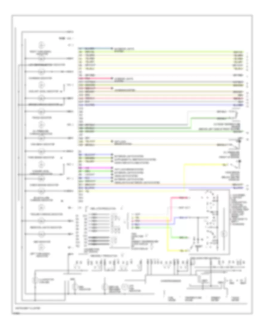
Электросхема панели приборов, VDO (1 из 2) для Volvo 850 1995
Электросхема панели приборов, VDO (1 из 2) для Volvo 850 1995 - Список элементов:

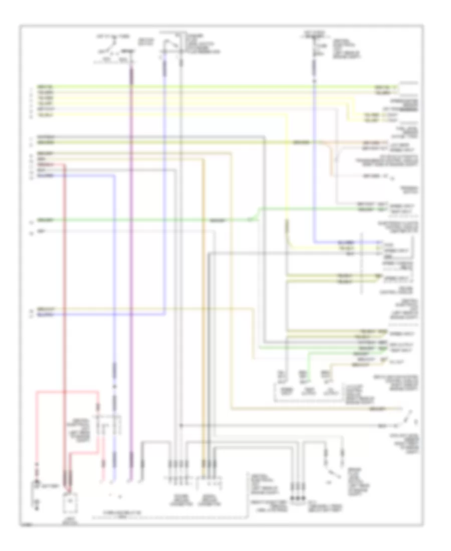
Электросхема панели приборов, VDO (2 из 2) для Volvo 850 1995
Электросхема панели приборов, VDO (2 из 2) для Volvo 850 1995 - Список элементов:
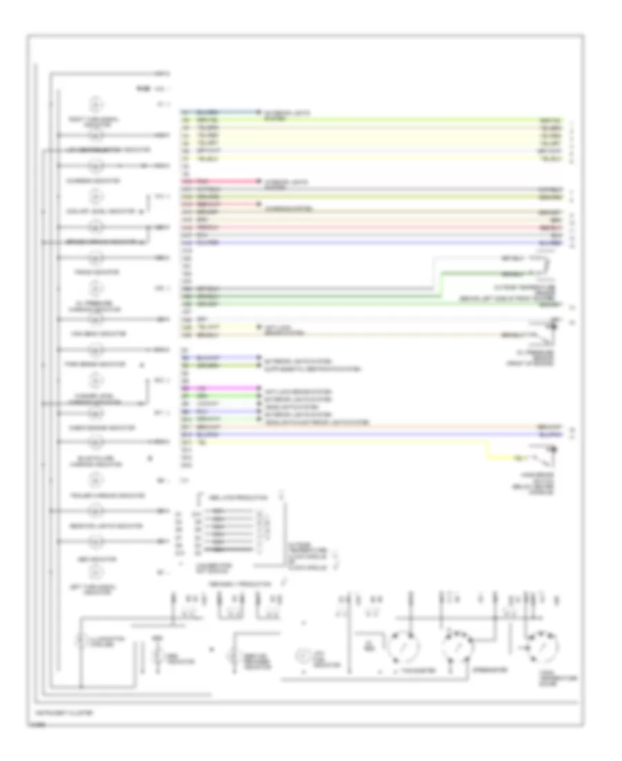
Электросхема панели приборов, Yasaki (1 из 2) для Volvo 850 1995
Электросхема панели приборов, Yasaki (1 из 2) для Volvo 850 1995 - Список элементов:
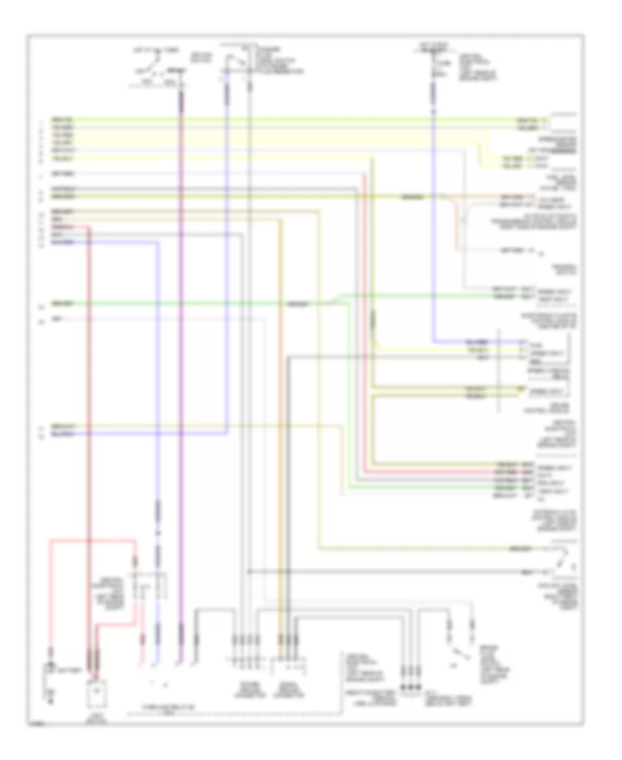
Электросхема панели приборов, Yasaki (2 из 2) для Volvo 850 1995
Электросхема панели приборов, Yasaki (2 из 2) для Volvo 850 1995 - Список элементов: