СИСТЕМА ПЕРЕДАЧИ ДАННЫХ
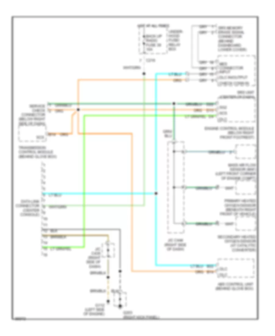
Электросхема линии передачи данных CAN для Acura 2.5TL 1997
Электросхема линии передачи данных CAN для Acura 2.5TL 1997 - Список элементов:
- (center console)
- Abs control unit (behind glove box)
- B14
- B22
- Back up radio fuse 39 10a
- C216
- Check conn in
- Connector (behind dashboard lower cover)
- Connector (below right side of dash)
- D13
- D22
- Data link connector
- Dlc
- Dlc in/output
- Engine control module (below right front footrest)
- G112 (left side of engine)
- G203 (right kick panel)
- Hot at all times
- J/c c436 (right side of dash)
- J/c c444 (right side of dash)
- Mass air flow sensor (maf) (left front corner of engine compt)
- Mes connector input
- Primary heated oxygen sensor (beneath right front of vehicle)
- Scs
- Secondary heated oxygen sensor (at catalytic converter)
- Service check
- Sg2
- Srs memory erase signal
- Srs unit (center of dash)
- Transmission control module (behind glove box)
- Under- hood fuse/ relay box
 Русский