СИСТЕМА ПЕРЕДАЧИ ДАННЫХ
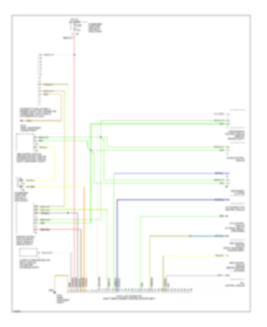
Электросхема компьютерной линии передачи данных CAN для Mercedes-Benz C280 1997
Электросхема компьютерной линии передачи данных CAN для Mercedes-Benz C280 1997 - Список элементов:
- A/c pushbutton control module
- Abs control module/ asr/sps control module/ ets/sps control module (right component compt)
- Asd control module (right component compartment)
- Ata control module (in trunk, below trim panel)
- Data link connector (right rear corner of engine compartment)
- Diagnostic module (obd ii) generic scan tool connector (under dash, right side of of steering column)
- Engine control module (me-sfi) (right rear of engine compt)
- Fuse 7.5a
- G105 (right component compartment)
- G105 (right component compt)
- Hot at all times
- Instrument cluster
- Ir das control module
- Overvoltage protection relay module (on center of engine compt)
- Passenger side fuse and relay module box
- Rcl control module
- Srs control module (behind center of dash)
- Transmission control module (rear of engine compt)
 Русский