СИСТЕМА ПЕРЕДАЧИ ДАННЫХ
Электросхема компьютерной линии передачи данных CAN для Volvo 850 1995
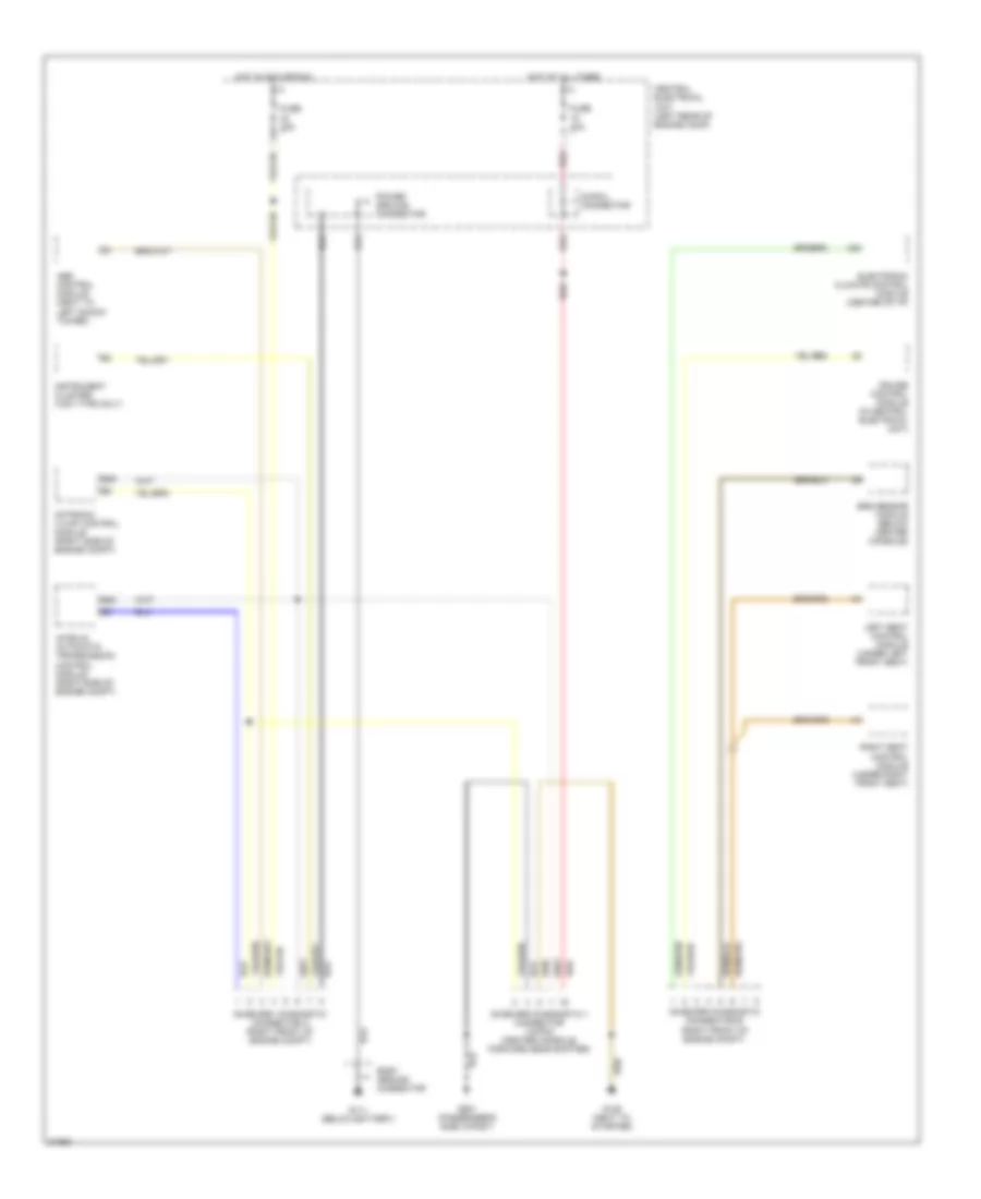
Электросхема компьютерной линии передачи данных CAN для Volvo 850 1995 - Список элементов:
- 30-rail connector
- A30
- Abs control module (next to left shock tower)
- Aw50-42 automatic transmission control module (right side of engine compt)
- B22
- B36
- Body ground connector
- Central electrical unit (left rear of engine comp)
- Cruise control module (in central electrical unit)
- Electronic climate control module (center of i/p)
- Fuse 10a
- Fuse 15a
- G111 (below battery)
- G125 (next to starter)
- G901 (passenger's side a-post)
- Hot at all times
- Hot in acc or run
- Instrument cluster (vdo type only)
- Left seat control module (under left front seat)
- Motronic 4.3 mfi control module (right side of engine compt)
- On-board diagnostic connector a (right front of engine compt)
- On-board diagnostic connector b (right front of engine compt)
- On-board diagnostic ii connector (16-pin) (center console, forward gear shifter)
- Power ground connector
- Red
- Right seat control module (under right front seat)
- Srs sensor module (below center console)
 Čeština
 Dansk
Dansk Deutsch
 Ελληνικά
 English
 English
 Español
 Suomi
Suomi Français
 Français
 עברית
עברית Hrvatski
 Magyar
 Italiano
 日本語
日本語 한국어
한국어 Nederlands
 Polski
 Português
 Português
 Română
 Slovenčina
 Slovenščina
 Svenska
 Türkçe
 中文 (中国)
 Русский