СИСТЕМА ПЕРЕДАЧИ ДАННЫХ
Электросхема компьютерной линии передачи данных CAN для Volvo V70 1998
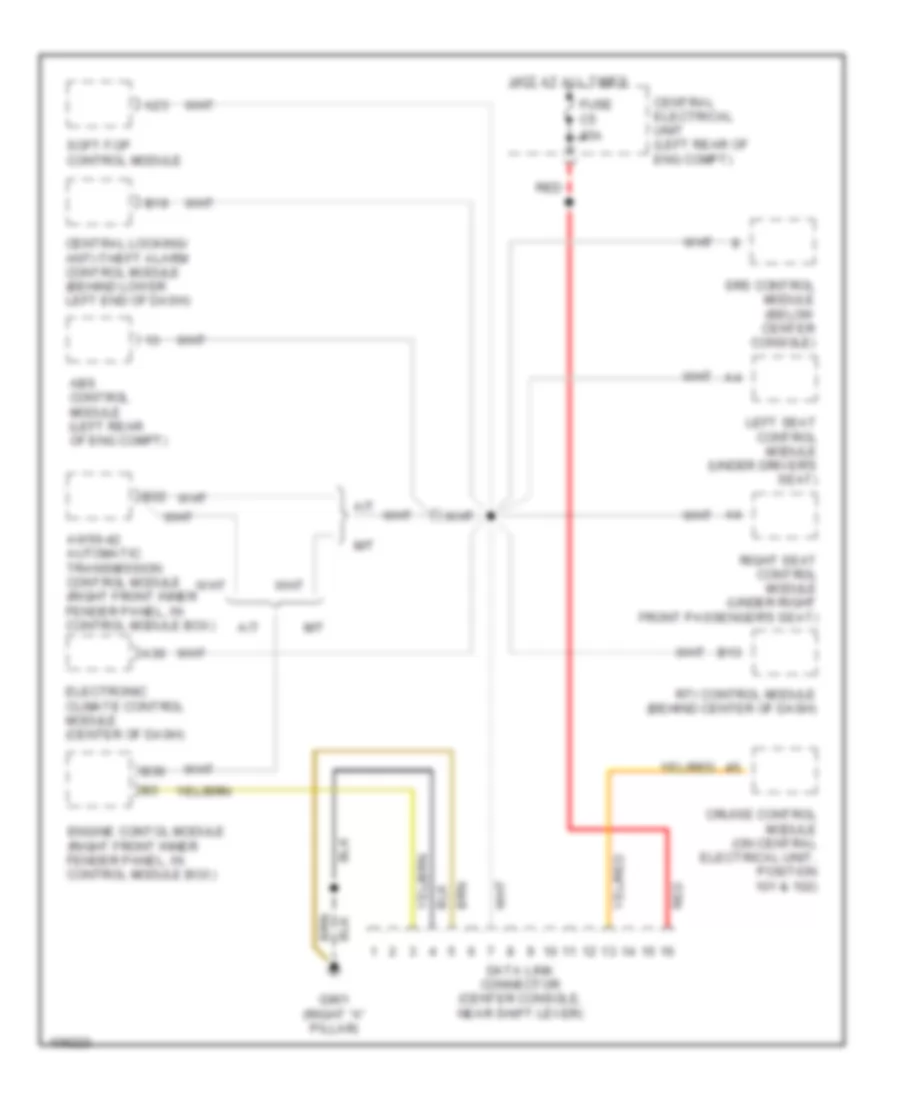
Электросхема компьютерной линии передачи данных CAN для Volvo V70 1998 - Список элементов:
- A/t
- A23
- A30
- Abs control module (left rear of eng compt)
- Aw50-42 automatic transmission control module (right front inner fender panel, in control module box)
- B13
- B19
- B22
- B36
- Central electrical unit (left rear of eng compt)
- Central locking/ anti-theft alarm control module (behind lower left end of dash)
- Cruise control module (on central electrical unit, position 101 & 102)
- Data link connector (center console, near shift lever)
- Electronic climate control module (center of dash)
- Engine contol module (right front inner fender panel, in control module box)
- Fuse c5 15a
- G901 (right "a" pillar)
- Hot at all times
- Left seat control module (under driver's seat)
- M/t
- Red
- Right seat control module (under right front passenger's seat)
- Rti control module (behind center of dash)
- Soft-top control module
- Srs control module (below center console)
 Čeština
 Dansk
Dansk Deutsch
 Ελληνικά
 English
 English
 Español
 Suomi
Suomi Français
 Français
 עברית
עברית Hrvatski
 Magyar
 Italiano
 日本語
日本語 한국어
한국어 Nederlands
 Polski
 Português
 Português
 Română
 Slovenčina
 Slovenščina
 Svenska
 Türkçe
 中文 (中国)
 Русский