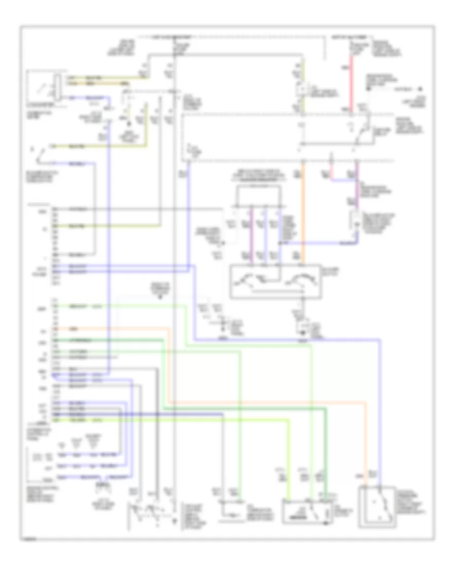
AIR CONDITIONING
A/C Wiring Diagram for Toyota Tundra SR5 2000
List of elements for A/C Wiring Diagram for Toyota Tundra SR5 2000:
- (3.4l) (4.7l)
- (4.7l)
- (below right side of dash, in blower housing) blower resistor
- (dash harn, upper right side of dash i16
- (dash harn, upper right side of dash) i4
- (engine room harn, in engine room r/b) e3
- (right of steering column) i2
- 4.7l
- A/c dual pressure switch (right front corner of engine compt)
- A/c fuse 10a
- A/c lock sensor
- A/c magnetic clutch
- A/c thermistor (behind right side of dash)
- A10
- A11
- A12
- A13
- A14
- A15
- A16
- A17
- A18
- A19
- A20
- A21
- A3 (4.7l)
- Ac+2
- Ac1 a/c
- Ac2
- Act
- Air inlet control servo (behind right side of dash)
- B1 (3.4l)
- B10
- B11
- B12
- B13
- B14
- B25
- Blower motor (below right side of dash, in blower housing)
- Blower switch
- Blower switch & defroster mode switch
- Calif 3.4l
- Combination meter
- Driver side j/b (lower left side of dash)
- E1 (engine room harn, in engine room r/b)
- Engine control module (behind right side of dash)
- Engine room r/b (left side of engne compt)
- Except calif 3.4l
- Frs
- G102 (left front fender)
- G200
- G200 (left kick panel)
- G203
- Gauge fuse 10a
- Gnd
- Heater fuse 50a
- Heater relay
- Hot at all times
- Hot in on or start
- Ig+
- Ig-
- Integraton control & panel
- J/c (left side of engine compt)
- J/c 12 (right side of dash)
- J/c 13 (right kick panel)
- J/c 3 (left kick panel)
- J/c 8 (right of steering column)
- Lock
- Mgc
- Off
- Power
- Rec
- Red
- Ssr-
- Tach
- Tachometer
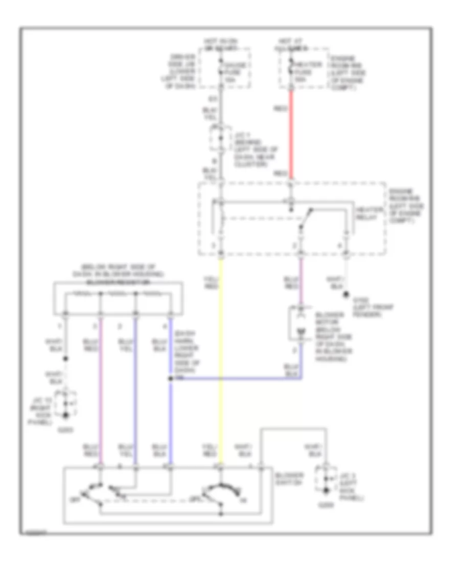
Heater Wiring Diagram for Toyota Tundra SR5 2000
List of elements for Heater Wiring Diagram for Toyota Tundra SR5 2000:
- (below right side of dash, in blower housing) blower resistor
- (dash harn, lower right side of dash) i16
- Blower motor (below right side of dash, in blower housing)
- Blower switch
- Driver side j/b (lower left side of dash)
- Engine room r/b (left side of engne compt)
- G102 (left front fender)
- G200
- G203
- Gauge fuse 10a
- Heater fuse 50a
- Heater relay
- Hot at all times
- Hot in on or start
- J/c 1 (behind left side of dash, near cluster)
- J/c 13 (right kick panel)
- J/c 3 (left kick panel)
- Off
- Red
Manual A/C Wiring Diagram for Toyota Tundra SR5 2000
List of elements for Manual A/C Wiring Diagram for Toyota Tundra SR5 2000:
- (3.4l) (4.7l)
- (4.7l)
- (below right side of dash, in blower housing) blower resistor
- (dash harn, upper right side of dash i16
- (dash harn, upper right side of dash) i4
- (engine room harn, in engine room r/b) e3
- (right of steering column) i2
- 4.7l
- A/c dual pressure switch (right front corner of engine compt)
- A/c fuse 10a
- A/c lock sensor
- A/c magnetic clutch
- A/c thermistor (behind right side of dash)
- A10
- A11
- A12
- A13
- A14
- A15
- A16
- A17
- A18
- A19
- A20
- A21
- A3 (4.7l)
- Ac+2
- Ac1 a/c
- Ac2
- Act
- Air inlet control servo (behind right side of dash)
- B1 (3.4l)
- B10
- B11
- B12
- B13
- B14
- B25
- Blower motor (below right side of dash, in blower housing)
- Blower switch
- Blower switch & defroster mode switch
- Calif 3.4l
- Combination meter
- Driver side j/b (lower left side of dash)
- E1 (engine room harn, in engine room r/b)
- Engine control module (behind right side of dash)
- Engine room r/b (left side of engne compt)
- Except calif 3.4l
- Frs
- G102 (left front fender)
- G200
- G200 (left kick panel)
- G203
- Gauge fuse 10a
- Gnd
- Heater fuse 50a
- Heater relay
- Hot at all times
- Hot in on or start
- Ig+
- Ig-
- Integraton control & panel
- J/c (left side of engine compt)
- J/c 12 (right side of dash)
- J/c 13 (right kick panel)
- J/c 3 (left kick panel)
- J/c 8 (right of steering column)
- Lock
- Mgc
- Off
- Power
- Rec
- Red
- Ssr-
- Tach
- Tachometer

 Čeština
 Dansk
Dansk Deutsch
 Ελληνικά
 English
 English
 Español
 Suomi
Suomi Français
 Français
 עברית
עברית Hrvatski
 Magyar
 Italiano
 日本語
日本語 한국어
한국어 Nederlands
 Polski
 Português
 Português
 Română
 Slovenčina
 Slovenščina
 Svenska
 Türkçe
 中文 (中国)