БЛОК ПРЕДОХРАНИТЕЛЕЙ И РЕЛЕ
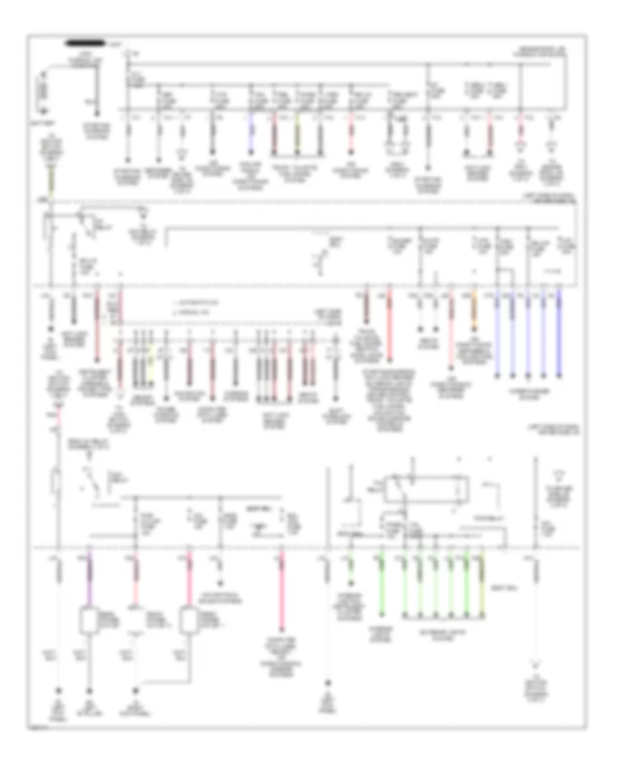
Электросхема блока предохранителей и реле (1 из 3) для Toyota Sienna CE 2010
Электросхема блока предохранителей и реле (1 из 3) для Toyota Sienna CE 2010 - Список элементов:
- (engine room j/b) fusible link block
- (left side of dash)
- (left side of dash) driver side j/b
- Abs 1 fuse 50a
- Abs 2 fuse 30a
- Acc
- Acc relay
- Air conditioning & defogger systems
- Air conditioning system
- Air conditioning, defogger & cooling fans systems
- Alt fuse 140a
- Am1 fuse 7.5a
- Anti-lock
- Anti-lock brakes system
- Automatic a/c
- Battery
- Bh (left "b" pillar)
- Body ecu
- Brakes system
- Cig fuse 15a
- Computer data lines system
- Computer data lines, memory, air conditioning & mirrors systems
- Cooling fans & air conditioning systems
- Def fuse 40a
- Defogger system
- Ecu acc fuse 7.5a
- Ecu-ig fuse 10a
- Exterior lights system
- F10
- F11
- F12
- F13
- F14
- F21
- Fan fuse 50a
- From ig1 relay (diagram 1 of 3)
- Front power outlet 1
- Front power outlet 2
- Gauge1 fuse 10a
- Htr fuse 10a
- Htr fuse 50a
- Ie (left kick panel)
- Ig (right kick panel)
- Ig1 relay
- Instrument cluster, mirrors & power tops systems
- Interior lights & instrument cluster systems
- Interior lights system
- J/c 18
- K18 pnk
- L-psd fuse 30a
- L23
- L26 red
- L8 pnk
- Manual a/c
- Memory systems
- Navigation & sound systems
- Navigation system
- Panel fuse 10a
- Pbd fuse 30a
- Pnk
- Power windows system
- Pwr outlet fuse 15a
- Pwr relay
- R-psd fuse 30a
- R/b 3 (diagram 3 of 3)
- Rad2 fuse 7.5a
- Rear power outlet
- Red
- Relay
- Rr a/c fuse 40a
- Rr wip fuse 15a
- Rr2 seat fuse 50a
- S-htr fuse 15a
- Seats
- Seats system
- Shift interlock system
- St fuse 30a
- Starting/ charging system
- Starting/charging, anti-lock brakes, exterior lights, transmissions, cruise control, trunk, tailgate, fuel doors, navigation, sound & engine controls systems
- System
- Tail
- Tail fuse 10a
- To acc relay (diagram 1 of 3)
- To driver side j/b (diagram 2 of 3)
- To engine room j/b (diagram 3 of 3)
- To ignition switch (diagram 2 of 3)
- To main switch (diagram 2 of 3)
- To r/b 3 (diagram 3 of 3)
- Trunk, tailgate, fuel doors system
- Trunk, tailgate, fuel doors, seats & door locks systems
- Warning systems
- Wip fuse 30a
- Wiper/washer system
- Wsh fuse 20a
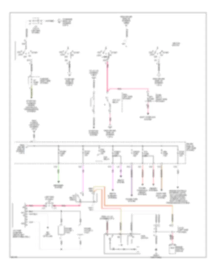
Электросхема блока предохранителей и реле (2 из 3) для Toyota Sienna CE 2010
Электросхема блока предохранителей и реле (2 из 3) для Toyota Sienna CE 2010 - Список элементов:
- (left end of dash) j/c j11 & j12
- Ac inv fuse 15a
- Ac1
- Ac2
- Acc
- Acc cut relay
- Am1
- Am2
- Anti-lock brakes,
- Bh (left "b" pillar)
- C16
- Computer data lines system
- Control module
- Cruise control, interior lights,
- Defogger system
- Driver side j/b (left side of dash)
- Engine controls, exterior lights,
- Engine els
- Fog fuse 15a
- Fog relay
- Fr def fuse 15a
- From driver h
- From driver side j/b (diagram 1 of 3)
- From fusible link block (diagram 1 of 3)
- From j/c j18 (diagram 1 of 3)
- Fuse box (right side of dash)
- Fuse box 2 (right side of dash)
- Ig (right kick panel)
- Ig1
- Ig2
- Ignition switch
- Inv relay (r/b 8)
- J/c 20 (left side of dash)
- J/c j3 & j4 (left end of dash)
- J11
- J12
- K12
- K16
- K21
- K33
- K34
- L21
- Lock
- Main switch
- Memory systems
- Obd fuse 7.5a
- Off
- P/seat fuse 30a
- P/w fuse 25a
- P10
- Pnk
- Power outlet 1 (115v)
- Power outlet 2 (115v)
- Power tops system
- Power windows & memory systems
- R/b 8 (left side of dash)
- R12
- S/roof fuse 25a
- Seats & memory systems
- Seats system
- Sft fuse 5a
- Shift interlock &
- Shift interlock system
- Side j/b (diagram 1 of 3)
- St fuse 7.5a
- St2
- Start
- Starting/ charging system
- Starting/ charging, engine controls & transmissions systems
- Stop fuse 10a
- To driver side j/b (diagram 3 of 3)
- To engine room j/b (diagram 3 of 3)
- To j/c j19 (diagram 3 of 3)
- Transmissions systems
- Voltage inverter (above left rear wheelwell)
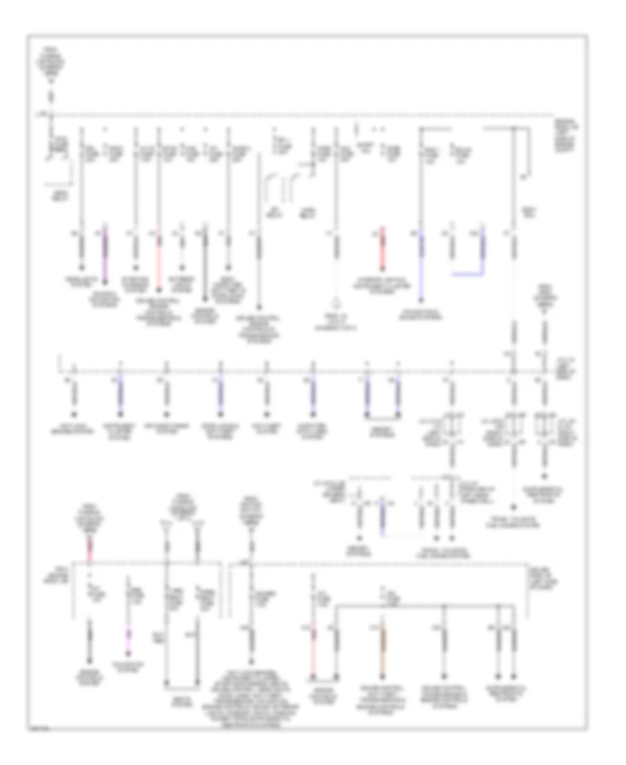
Электросхема блока предохранителей и реле (3 из 3) для Toyota Sienna CE 2010
Электросхема блока предохранителей и реле (3 из 3) для Toyota Sienna CE 2010 - Список элементов:
- A/f fuse 25a
- Air conditioning system
- Alt-s fuse 7.5a
- Am2 fuse 30a
- Anti-lock brakes system
- Anti-theft system
- Body computer, anti-theft & door locks systems
- Body ecu
- C3 red
- Computer data lines system
- Cruise control, anti-theft, transmissions &
- Cruise control, engine controls & transmissions systems
- Cruise control, engine controls, transmissions & systems
- Cruise control, transmissions & engine controls systems
- Dome fuse 10a
- Door 2 fuse 25a
- Door locks & anti-theft systems
- Driver side j/b (left side of dash)
- Drl fuse 20a
- Ecu-b fuse 10a
- Efi 1 fuse 20a
- Efi relay
- Engine controls system
- Engine controls systems
- Engine room j/b (left side of engine compt)
- Etcs fuse 10a
- Exterior lights system
- From fusible
- From fusible link block (diagram 1 of 3)
- From ignition switch (diagram 2 of 3)
- From j/c j3 & j4 (diagram 2 of 3)
- From r/b 8 (diagram 2 of 3)
- Gauge2 fuse 7.5a
- H18 red
- H27
- H3 red
- Haz fuse 15a
- Head relay
- Headlights system
- Horn fuse 10a
- Horn relay
- Ig 2 fuse 7.5a
- Ign fuse 7.5a
- Instrument cluster system
- Int fuse 10a
- Interior lights & instrument cluster systems
- J/c j13 & j14 (left end of dash)
- J/c j19 (left side of dash)
- J/c j33 & j34 (right side of dash)
- J/c j35 & j36 (right side of dash)
- J/c j37 (forward of left rear wheelwell)
- J/c j44 & j45 (under driver's seat)
- J13
- J14
- J33
- J34
- J35
- J36
- J44
- J45
- L-rr2 seat fuse 30a
- Link block (diagram 1 of 3)
- Main fuse 30a
- Memory systems
- Navigation & sound systems
- Navigation system
- Pin
- Pnk
- R-rr2 seat fuse 30a
- R/b 3 (engine room j/b)
- Rad 1 fuse 15a
- Rad 3 fuse 30a
- Rse fuse 7.5a
- Seats system
- Short
- Sound & navigation systems
- Starting/ charging system
- Trunk, tailgate, fuel doors system

 Čeština
 Dansk
Dansk Deutsch
 Ελληνικά
 English
 English
 Español
 Suomi
Suomi Français
 Français
 עברית
עברית Hrvatski
 Magyar
 Italiano
 日本語
日本語 한국어
한국어 Nederlands
 Polski
 Português
 Português
 Română
 Slovenčina
 Slovenščina
 Svenska
 Türkçe
 中文 (中国)