СИСТЕМА АНТИБЛОКИРОВОЧНОЙ ТОРМОЗНОЙ СИСТЕМЫ ABS
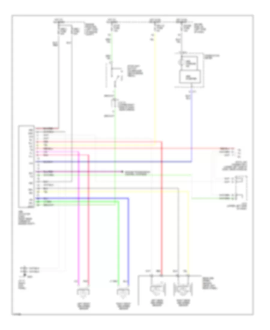
Электросхема антиблокировочной тормозной системы АБС (ABS) для Toyota Tundra 2001
Электросхема антиблокировочной тормозной системы АБС (ABS) для Toyota Tundra 2001 - Список элементов:
- +bm
- +bs
- Abs 1 fuse 40a
- Abs 2 fuse 40a
- Abs actuator & ecu (right rear corner of engine compt)
- Abs inverter
- Abs warning ind
- C11
- Combination meter
- D/g
- Data link connector 3 (under left side of dash, near console)
- Driver side j/b (left side of dash)
- Ecu ig fuse 5a
- Engine room r/b (left side of engine compt)
- Engine/transmission control systems
- Exi
- Fl+
- Fl-
- Fr+
- Fr-
- G203
- Gauge fuse 10a
- Gnd
- Hot at all times
- Hot in on or start
- Ig1
- J/c 12 (upper right side of dash, near airbag)
- J/c 13 (right kick panel)
- J/c 5 (upper left side of dash)
- Left front abs speed sensor
- Left rear abs speed sensor
- Pnk
- Rear abs speed sensor (near left rear wheel)
- Red
- Right front abs speed sensor
- Right rear abs speed sensor
- Rl+
- Rl-
- Rr+
- Rr-
- Sil
- Stop fuse 15a
- Stoplight switch (on bracket above brake pedal)
- Stp
 Čeština
 Dansk
Dansk Deutsch
 Ελληνικά
 English
 English
 Español
 Suomi
Suomi Français
 Français
 עברית
עברית Hrvatski
 Magyar
 Italiano
 日本語
日本語 한국어
한국어 Nederlands
 Polski
 Português
 Português
 Română
 Slovenčina
 Slovenščina
 Svenska
 Türkçe
 中文 (中国)
 Русский