СИСТЕМА КОНДИЦИОНЕРА
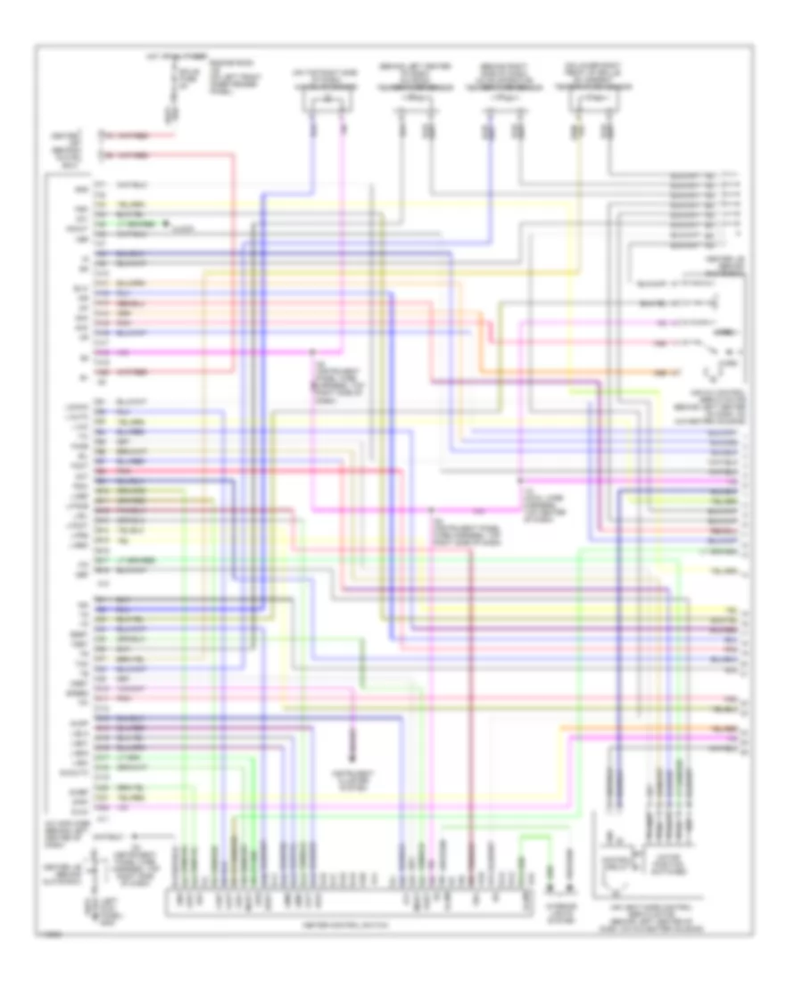
Электросхема кондиционера (1 из 2) для Toyota Avalon XLS 1999
Электросхема кондиционера (1 из 2) для Toyota Avalon XLS 1999 - Список элементов:
- (behind left center of dash) a/c room temperature sensor
- (behind right side of dash) a/c evaporator temperature sensor
- (left kick panel) g200
- (on lower right front of grille) a/c ambient temperature sensor
- (on top right side of dash) a/c solar sensor
- A/c amplifier (behind left center of dash)
- A10
- A11
- A12
- A13
- A14
- A15
- A16
- A17
- A18
- A19
- A20
- Ac1
- Act
- Aif
- Air
- Air mix control servo motor (behind left center of dash, on a/c-heater housing)
- Air vent mode control servo motor (behind left center of dash, on a/c-heater housing)
- Amc
- Amh
- Amout
- B/l
- B10
- B11
- B12
- B13
- B14
- B15
- B16
- B17
- B18
- Blw
- Bset
- C10
- C11
- C12
- C13
- C14
- C15
- C16
- C17
- C18
- C19
- C20
- C21
- C22
- Center j/b (behind glove box)
- Clock
- Control circuit
- Cool
- Dash)
- Def
- Ecu-b fuse 5a
- Engine room j/b (on left front inner fender panel)
- F/d
- Face
- Foot
- Gnd
- H14
- H15
- Heater control switch
- Hot at all times
- I12 (cowl wire harness, top center of dash)
- I22 (instrument panel wire harness, top right side of dash)
- I22 (instrument panel wire harness, top right side of dash)
- Ign
- Illum
- Instrument cluster system
- Interior lights system
- L-a/c
- L-auto
- L-b/l
- L-bhi
- L-blo
- L-bm1
- L-bm2
- L-def
- L-face
- L-foot
- L-frs
- L-rec
- Laut
- Lb/l
- Lbhi
- Lblo
- Lbm1
- Lbm2
- Ldef
- Led+
- Lfot
- Lockin
- Lvnt
- Maut
- Mgc
- Motor position switches
- Mset
- Off
- Pnk
- Psw
- S-a/c
- S-def
- S-mauto
- S-off
- S-r/f
- Speed
- Tam
- Tpi
- Tset
- Vent
- Ver
- Warm
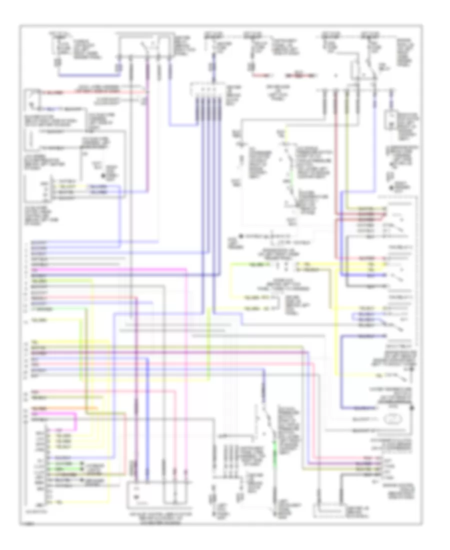
Электросхема кондиционера (2 из 2) для Toyota Avalon XLS 1999
Электросхема кондиционера (2 из 2) для Toyota Avalon XLS 1999 - Список элементов:
- (a/c sub wire harness, left side of dash)
- (a/c sub wire harness, left side of dash) i28
- (cowl wire harness, top rght side of dash)
- (instrument panel wire harness, top right side of dash)
- (left instrument panel brace) g206
- (left kick panel) g200
- (right fender) g101
- A/c
- A/c blower motor linear controller (behind left side of dash)
- A/c condenser fan motor (on right front of engine compart- ment)
- A/c dual pressure switch (part of a/c triple pressure switch) (on lower left front of engine compart- ment)
- A/c magnetic clutch & lock sensor (on a/c compressor)
- A/c single pressure switch (part of a/c triple pressure switch) (on lower left front of engine compartment)
- A/c switch
- Act
- Air inlet control servo motor (behind glove box, on a/c-heater housing)
- B12
- Blower motor (below right side of dash, on a/c heater housing)
- Cds fuse 30a
- Center j/b (behind glove box)
- Defogger system
- Diode (a/c) (behind left kick panel, taped to harness)
- Driver side j/b (behind left kick panel)
- Driver side j/b (left kick panel)
- E11
- Ecu-ig fuse 10a
- Engine control module (behind right side of dash)
- Engine room j/b (on left front inner fender panel)
- Engine room r/b (on left rear of engine compartment, next to shock tower)
- Fan relay
- Fan relay 2
- Fan relay 3
- Floor shift column shift
- Fusible link block (on left front inner fender panel)
- G100 (left fender)
- Gnd
- Heater fuse 10a
- Heater relay (behind right kick panel)
- Hot at all times
- Hot in on or start
- Htr fuse 50a
- I19
- I22
- I28
- Ig +
- Illum
- Instrument panel j/b (behind left side of dash)
- Interior lights system
- La/c
- Led+
- Lfrs
- Low speed blower resistor (behind left center of dash)
- Lrec
- Main wire harness, left side of grille) e4
- Mg clt relay
- Pnk
- Radiator fan motor (on left front of engine compart- ment)
- Rdef
- Rdi fuse 30a
- Sa/c
- Sf/r
- Tach
- Twho
- Water temperature switch 1 (on top rear of intake)
- Water temperature switch 2 (on top rear of intake manifold)
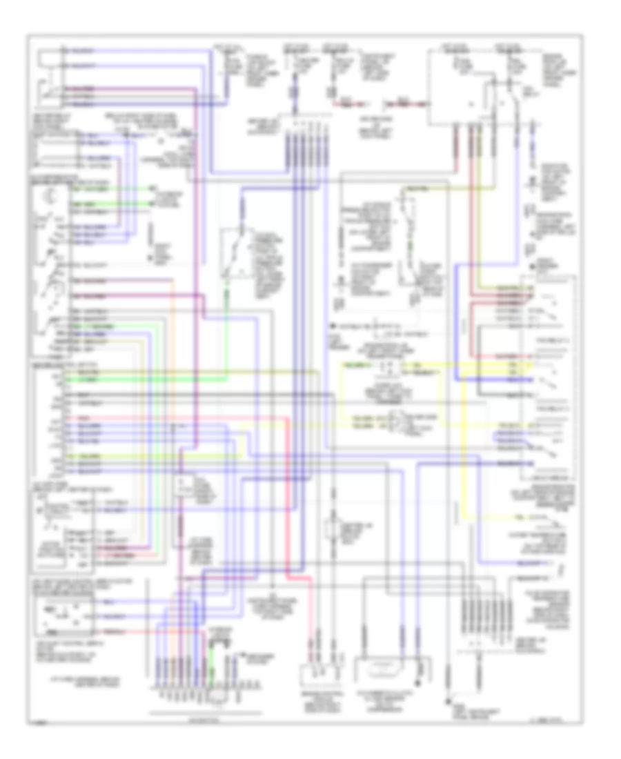
Электросхема кондиционера с ручный управлением для Toyota Avalon XLS 1999
Электросхема кондиционера с ручный управлением для Toyota Avalon XLS 1999 - Список элементов:
- (cowl wire harness, top right side of dash)
- (engine room main wire harness, left side of grille) e4
- (i/p wire harness, behind center of dash)
- (right fender) g101
- (right kick panel) g203
- 10a
- 1995 vftc c
- A/c
- A/c amplifier (behind left center of dash)
- A/c condenser fan motor (on right front of engine compartment)
- A/c dual pressure switch (part of a/c triple pressure switch) (on lower left front of engine compart- ment)
- A/c evaporator temperature sensor (behind right side of dash, on evaporator housing)
- A/c fuse (right side of dash)
- A/c magnetic clutch & lock sensor (on a/c compressor)
- A/c single pressure switch (part of a/c triple pressure switch) (on lower left front of engine compartment)
- A/c switch
- Ac1
- Act
- Air inlet control servo motor (behind glove box, on a/c-heater housing)
- Air vent mode control servo motor (behind left center of dash, on a/c-heater housing)
- B/l
- B12
- Blower resistor (behind left center of dash)
- Cds fuse 30a
- Center j/b (behind glove box)
- Control circuit
- D13
- D25
- D27
- Def
- Defogger system
- Diode (a/c) (behind left kick panel, taped to harness)
- Driver side j/b (behind left kick panel)
- Driver side j/b (left kick panel)
- E11
- Ecu-ig fuse 10a
- Engine control module (behind right side of dash)
- Engine room j/b (on left front inner fender panel)
- Engine room r/b (on left rear of engine compartment, next to shock tower)
- F/d
- Face
- Fan relay
- Fan relay 2
- Fan relay 3
- Foot
- Frs
- Fusible link block (on left front inner fender panel)
- G100 (left fender)
- G206 (left instrument panel brace)
- Gnd
- Ha/c
- Heater control switch
- Heater fuse 10a
- Heater relay (behind right kick panel)
- Hot at all times
- Hot in on
- Hot in on or start
- Htr fuse 50a
- I14
- I19 or i20
- I22 (instrument panel wire harness, top right side of dash)
- Ig+
- Ign
- Instrument panel j/b (behind left side of dash)
- Interior lights system
- L-a/c
- La/c
- Lock
- Mg clt relay
- Mgc
- Motor position switches
- Off
- Or start
- Pnk
- Radiator fan motor (on left front of engine compart- ment)
- Rdef
- Rdi fuse 30a
- Rec
- S-a/c
- Sa/c
- Sfrs
- Srec
- Tach
- Vent
- Water temp switch 1 (on top rear of intake)
- Water temperature switch 2 (on top rear of intake manifold)

 Čeština
 Dansk
Dansk Deutsch
 Ελληνικά
 English
 English
 Español
 Suomi
Suomi Français
 Français
 עברית
עברית Hrvatski
 Magyar
 Italiano
 日本語
日本語 한국어
한국어 Nederlands
 Polski
 Português
 Português
 Română
 Slovenčina
 Slovenščina
 Svenska
 Türkçe
 中文 (中国)