TRANSMISSION
2.7L
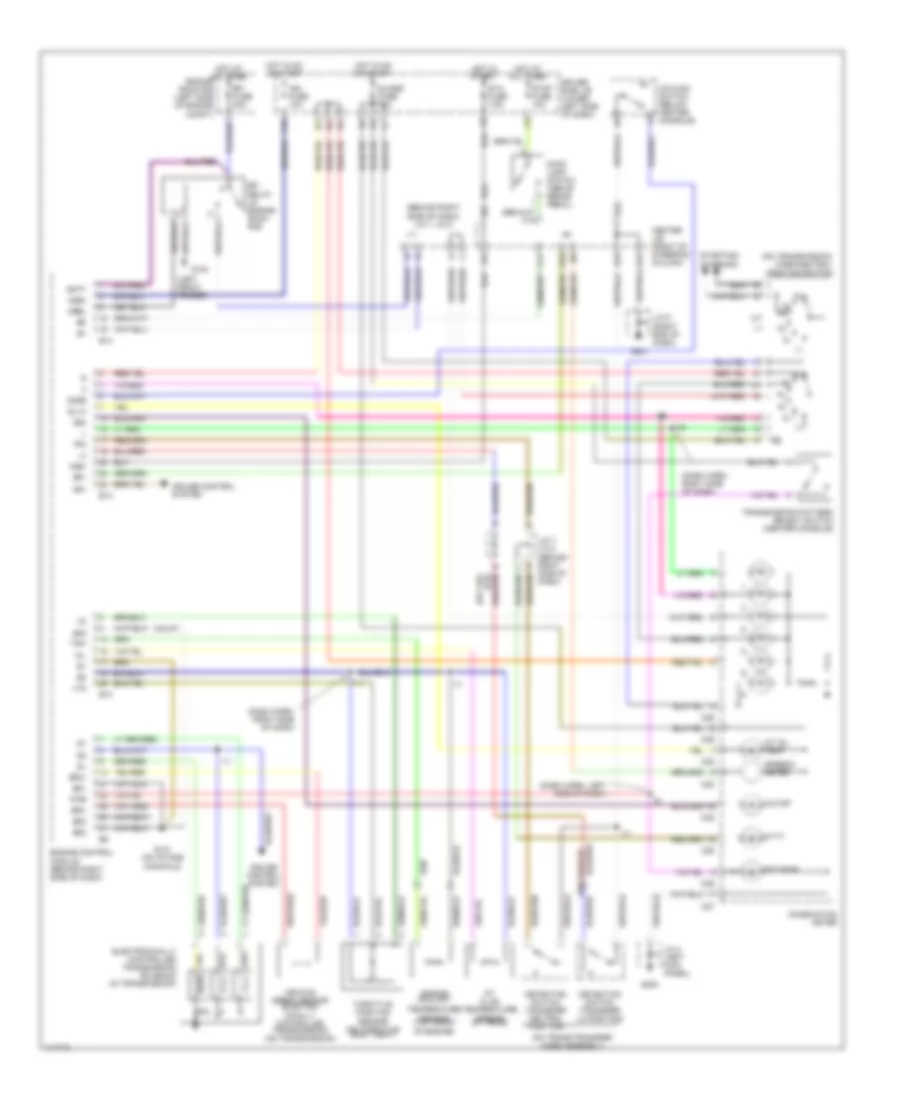
2.7L, A/T Wiring Diagram for Toyota 4Runner SR5 2000

List of elements for 2.7L, A/T Wiring Diagram for Toyota 4Runner SR5 2000:
- (behind right side of dash) j/c 7, j/c 8
- (dash harn, left side of dash)
- (dash harn, right side of dash)
- (left front fender) g100
- (on trans/transfer case assembly)
- (on transmission) park/neutral position switch
- A/t fluid temperature sensor (in trans)
- A/t oil temp
- A/t p
- Batt
- C11
- C25
- C26
- C27
- C28
- C29
- Calif
- Center j/b (right of steering column)
- Combination meter
- Cruise control system
- Detection switch (transfer l4 position)
- Detection switch (transfer neutral position)
- Driver side j/b (lower left side of dash)
- E10
- E16
- E18
- E22
- Ect pwr
- Efi
- Efi fuse 20a
- Electronically controlled transmission solenoid (in transmission)
- Engine control module (behind right side of dash)
- Engine coolant
- Engine room r/b (left side of engine compt)
- Eo1
- Eo2
- Eo3
- Eo4
- Ex-calif
- F10
- G131 (on intake manifold)
- G200
- G201
- Gauge fuse 10a
- Hot at all times
- Hot in on or start
- Hot in start
- I11
- I19
- Ign fuse 10a
- J/c 1, j/c 2 (left fender panel)
- J/c 4 (left kick panel)
- J/c 7, j/c 8 (behind right side of dash)
- J/c 9 (upper right end of dash)
- Nsw
- O/d main switch (below center console)
- O/d off
- Od1
- Odlp
- Odms
- Oil
- Oil-w
- Pwr
- Relay (in engine room r/b)
- Rl nl
- Sol
- Sp1
- Sp2+
- Sp2-
- Speedo- meter
- Sta fuse 7.5a
- Starting/ charging
- Stop fuse 10a
- Stop light switch (above brake pedal)
- Temperature sensor (top front of engine)
- Tfn
- Throttle position sensor (on throttle body assy)
- Thw
- Transmission pattern select switch (center console)
- Vehicle speed sensor (electro- nically controlled transmission) (in transmission)
- Vta
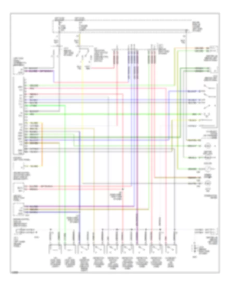
4WD Wiring Diagram, with 2-4 Select Switch for Toyota 4Runner SR5 2000
List of elements for 4WD Wiring Diagram, with 2-4 Select Switch for Toyota 4Runner SR5 2000:
- (behind left side of dash)
- (left kick panel) differential lock ecu
- 2-4
- 2-4 select motor (on transfer case)
- 2-4 select switch (on shift lever)
- 4wd
- 4wd ecu (left kick panel)
- 4wd fuse 20a
- 4wd ind
- A/t indicator light switch (part of park/neutral position switch)
- A/t p ind
- Abs ecu (right kick panel)
- Add
- Add indicator switch (center middle of engine compt)
- C/c
- C25
- C28
- C29
- Center diff lock
- Center j/b (behind left side of dash)
- Combination meter
- Cruise control actuator w/ecu (right side of engine compt)
- Detection switch (h2 & h4f) (transfer case)
- Detection switch (l4 position) (transfer case)
- Detection switch (n position) (transfer case)
- Detection switch (shift diff lock) (transfer case)
- Detection switch (transfer diff lock) (transfer case)
- Driver side j/b (lower left side of dash)
- E12
- E13
- E16
- Engine control module (behind right side of dash)
- Ex1
- Ex13
- G100
- G201
- Gauge fuse 10a
- Gnd
- Hot in on or start
- I11
- I12 (dash harn, right side of dash)
- I20 (dash harn, right side of dash)
- Ind1
- Ind2
- J/c 1, j/c 2 (left inner fender panel)
- J/c 3
- J/c 5 (behind left side of dash)
- J/c 7, j/c 8 (behind right side of dash)
- J/c 9 (behind right side of dash)
- Pnk
- Spd
- Speed- ometer
- Tfn
- Tl1
- Tl2
- Tl3
- Tm1
- Tm2
- Vsv (2wd, add) (left side of engine compt)
- Vsv (4wd, add) (left side of engine compt)
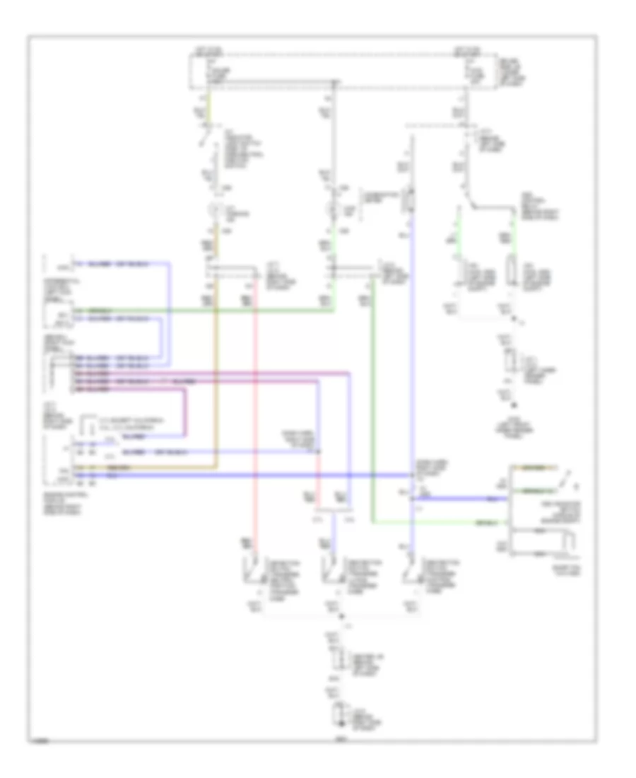
4WD Wiring Diagram, without 2-4 Select Switch for Toyota 4Runner SR5 2000
List of elements for 4WD Wiring Diagram, without 2-4 Select Switch for Toyota 4Runner SR5 2000:
- (behind left side of dash)
- (dash harn, right side of dash) i11
- (dash harn, right side of dash) i12
- (transfer case)
- 2.7l
- 2.7l except california
- 3.4l
- 3.4l, 2.7l california
- 4wd
- 4wd fuse 20a
- 4wd ind
- A/t indicator light switch (part of park/neutral position switch)
- A/t parking ind
- Abs ecu (right kick panel)
- Add control relay (behind right side of dash)
- Add indicator switch (middle of engine compt)
- C25
- C26
- C29
- Center j/b (behind left side of dash)
- Combination meter
- Dectection switch (transfer 4wd pos) (transfer case)
- Dectection switch (transfer l4 pos) (transfer case)
- Detection switch (transfer neutral position)
- Differential lock ecu (left kick panel)
- Driver side j/b (lower left side of dash)
- E13
- E16
- Engine control module (behind right side of dash)
- Ex1
- Ex13
- G100 (left front inner fender panel)
- G201
- Gauge fuse 10a
- Hot in on or start
- I11
- J/c 1, j/c 2 (left inner fender panel)
- J/c 3
- J/c 5 (behind left side of dash)
- J/c 7, j/c 8 (behind right side of dash)
- J/c 9 (behind right side of dash)
- Nca
- Short pin (w/o add)
- Tfn
- Vsv (2wd, add) (left side of engine compt)
- Vsv (4wd, add) (left side of engine compt)
- W/ add
- W/o add
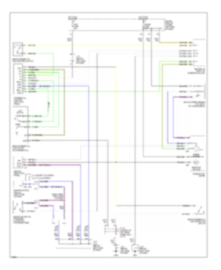
Rear Differential Lock Wiring Diagram for Toyota 4Runner SR5 2000
List of elements for Rear Differential Lock Wiring Diagram for Toyota 4Runner SR5 2000:
- (behind left side of dash)
- (dash harn, right side of dash) i11
- (in front of left rear wheelwell) j/c 12
- 2.7l
- 2.7l except california
- 3.4l
- 3.4l, 2.7l california
- 4wd
- 4wd fuse 20a
- A17
- Abs ecu (right kick panel)
- C28
- C29
- Center j/b (right of steering column)
- Combination meter
- Detection switch (transfer l4 position) (transfer case)
- Differential lock ecu (left kick panel)
- Driver side j/b (lower left side of dash)
- E12
- E14
- E16
- E18
- Engine control module (right side of dash)
- Exi2
- Exi3
- Free
- G201
- G202
- Gauge fuse 10a
- Gnd
- Hot in on or start
- J/c 13
- J/c 3
- J/c 4 (behind left side of dash)
- J/c 7,
- J/c 8 (behind right side of dash)
- J/c 9 (behind right side of dash)
- Limit switch
- Lock
- Rear diff lock ind
- Rear differential lock control switch
- Rear differential lock detection switch
- Rear differential lock motor (on differential)
- Rel1
- Rel2
- Rlp
- Rly1
- Rly2
- Sp1
- Spd
- Speed- ometer
- Vehicle speed sensor (2.7l only) (on transmission)
3.4L
3.4L, A/T Wiring Diagram for Toyota 4Runner SR5 2000
List of elements for 3.4L, A/T Wiring Diagram for Toyota 4Runner SR5 2000:
- (behind right side of dash) j/c 7, j/c 8
- (calif)
- (dash harn, left side of dash)
- (dash harn, right side of dash)
- (left front fender)
- (on trans/transfer case assembly)
- (on transmission) park/neutral position switch
- A/t fluid temperature sensor (in trans)
- A/t oil temp
- A/t p
- Batt
- C11
- C25
- C26
- C27
- C28
- C29
- Center j/b (right of steering column)
- Combination meter
- Cruise control system
- Detection switch (transfer l4 position)
- Detection switch (transfer neutral position)
- Driver side j/b (lower left side of dash)
- E05
- E10
- E12
- E14
- E16
- E18
- E22
- Ect pwr
- Efi
- Efi fuse 20a
- Electronically controlled transmission solenoid (in transmission)
- Engine control module (behind right side of dash)
- Engine coolant
- Engine room r/b (left side of engine compt)
- Eo1
- Eo2
- Eo3
- F10
- G100
- G131 (on intake manifold)
- G200
- G201
- Guage fuse 10a
- Hot at all times
- Hot in on or start
- Hot in start
- I11
- I19
- Ign fuse 10a
- Igsw
- J/c 4 (left kick panel)
- J/c 7, j/c 8 (behind right side of dash)
- J/c 9 (right end of dash)
- Mrel
- Nically controlled transmission) (on transmission)
- Nsw
- O/d main switch (below center console)
- O/d off
- Od1
- Od2
- Odms
- Oil
- Oil-w
- Pwr
- Relay (in engine room r/b)
- Rl nl
- Sol
- Sp1
- Sp2+
- Sp2-
- Speedo- meter
- Sta fuse 7.5a
- Starting/ charging
- Stop fuse 10a
- Stop light switch (above brake pedal)
- Temperature sensor (top front of engine)
- Tfn
- Throttle position sensor (on throttle body assy)
- Thw
- Transmission pattern select switch (center console)
- Vehicle speed sensor (electro-
- Vta
4WD Wiring Diagram, with 2-4 Select Switch for Toyota 4Runner SR5 2000
List of elements for 4WD Wiring Diagram, with 2-4 Select Switch for Toyota 4Runner SR5 2000:
- (behind left side of dash)
- (left kick panel) differential lock ecu
- 2-4
- 2-4 select motor (on transfer case)
- 2-4 select switch (on shift lever)
- 4wd
- 4wd ecu (left kick panel)
- 4wd fuse 20a
- 4wd ind
- A/t indicator light switch (part of park/neutral position switch)
- A/t p ind
- Abs ecu (right kick panel)
- Add
- Add indicator switch (center middle of engine compt)
- C/c
- C25
- C28
- C29
- Center diff lock
- Center j/b (behind left side of dash)
- Combination meter
- Cruise control actuator w/ecu (right side of engine compt)
- Detection switch (h2 & h4f) (transfer case)
- Detection switch (l4 position) (transfer case)
- Detection switch (n position) (transfer case)
- Detection switch (shift diff lock) (transfer case)
- Detection switch (transfer diff lock) (transfer case)
- Driver side j/b (lower left side of dash)
- E12
- E13
- E16
- Engine control module (behind right side of dash)
- Ex1
- Ex13
- G100
- G201
- Gauge fuse 10a
- Gnd
- Hot in on or start
- I11
- I12 (dash harn, right side of dash)
- I20 (dash harn, right side of dash)
- Ind1
- Ind2
- J/c 1, j/c 2 (left inner fender panel)
- J/c 3
- J/c 5 (behind left side of dash)
- J/c 7, j/c 8 (behind right side of dash)
- J/c 9 (behind right side of dash)
- Pnk
- Spd
- Speed- ometer
- Tfn
- Tl1
- Tl2
- Tl3
- Tm1
- Tm2
- Vsv (2wd, add) (left side of engine compt)
- Vsv (4wd, add) (left side of engine compt)
4WD Wiring Diagram, without 2-4 Select Switch for Toyota 4Runner SR5 2000
List of elements for 4WD Wiring Diagram, without 2-4 Select Switch for Toyota 4Runner SR5 2000:
- (behind left side of dash)
- (dash harn, right side of dash) i11
- (dash harn, right side of dash) i12
- (transfer case)
- 2.7l
- 2.7l except california
- 3.4l
- 3.4l, 2.7l california
- 4wd
- 4wd fuse 20a
- 4wd ind
- A/t indicator light switch (part of park/neutral position switch)
- A/t parking ind
- Abs ecu (right kick panel)
- Add control relay (behind right side of dash)
- Add indicator switch (middle of engine compt)
- C25
- C26
- C29
- Center j/b (behind left side of dash)
- Combination meter
- Dectection switch (transfer 4wd pos) (transfer case)
- Dectection switch (transfer l4 pos) (transfer case)
- Detection switch (transfer neutral position)
- Differential lock ecu (left kick panel)
- Driver side j/b (lower left side of dash)
- E13
- E16
- Engine control module (behind right side of dash)
- Ex1
- Ex13
- G100 (left front inner fender panel)
- G201
- Gauge fuse 10a
- Hot in on or start
- I11
- J/c 1, j/c 2 (left inner fender panel)
- J/c 3
- J/c 5 (behind left side of dash)
- J/c 7, j/c 8 (behind right side of dash)
- J/c 9 (behind right side of dash)
- Nca
- Short pin (w/o add)
- Tfn
- Vsv (2wd, add) (left side of engine compt)
- Vsv (4wd, add) (left side of engine compt)
- W/ add
- W/o add
Rear Differential Lock Wiring Diagram for Toyota 4Runner SR5 2000
List of elements for Rear Differential Lock Wiring Diagram for Toyota 4Runner SR5 2000:
- (behind left side of dash)
- (dash harn, right side of dash) i11
- (in front of left rear wheelwell) j/c 12
- 2.7l
- 2.7l except california
- 3.4l
- 3.4l, 2.7l california
- 4wd
- 4wd fuse 20a
- A17
- Abs ecu (right kick panel)
- C28
- C29
- Center j/b (right of steering column)
- Combination meter
- Detection switch (transfer l4 position) (transfer case)
- Differential lock ecu (left kick panel)
- Driver side j/b (lower left side of dash)
- E12
- E14
- E16
- E18
- Engine control module (right side of dash)
- Exi2
- Exi3
- Free
- G201
- G202
- Gauge fuse 10a
- Gnd
- Hot in on or start
- J/c 13
- J/c 3
- J/c 4 (behind left side of dash)
- J/c 7,
- J/c 8 (behind right side of dash)
- J/c 9 (behind right side of dash)
- Limit switch
- Lock
- Rear diff lock ind
- Rear differential lock control switch
- Rear differential lock detection switch
- Rear differential lock motor (on differential)
- Rel1
- Rel2
- Rlp
- Rly1
- Rly2
- Sp1
- Spd
- Speed- ometer
- Vehicle speed sensor (2.7l only) (on transmission)