Разделы схем — 24 (всего 42)
AIR CONDITIONING ANTI-LOCK BRAKES COMPUTER DATA LINES CRUISE CONTROL DEFOGGERS ENGINE PERFORMANCE EXTERIOR LIGHTS GROUND DISTRIBUTION HEADLIGHTS HORN INSTRUMENT CLUSTER INTERIOR LIGHTS POWER DISTRIBUTION POWER DOOR LOCKS POWER MIRRORS POWER SEATS POWER WINDOWS RADIO SHIFT INTERLOCKS STARTING/CHARGING SUPPLEMENTAL RESTRAINTS TRANSMISSION WARNING SYSTEMS WIPER/WASHER
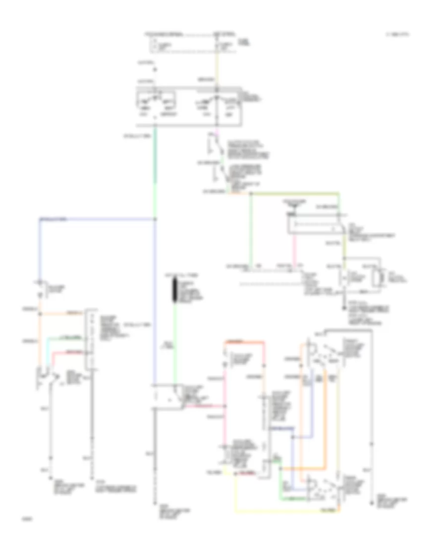
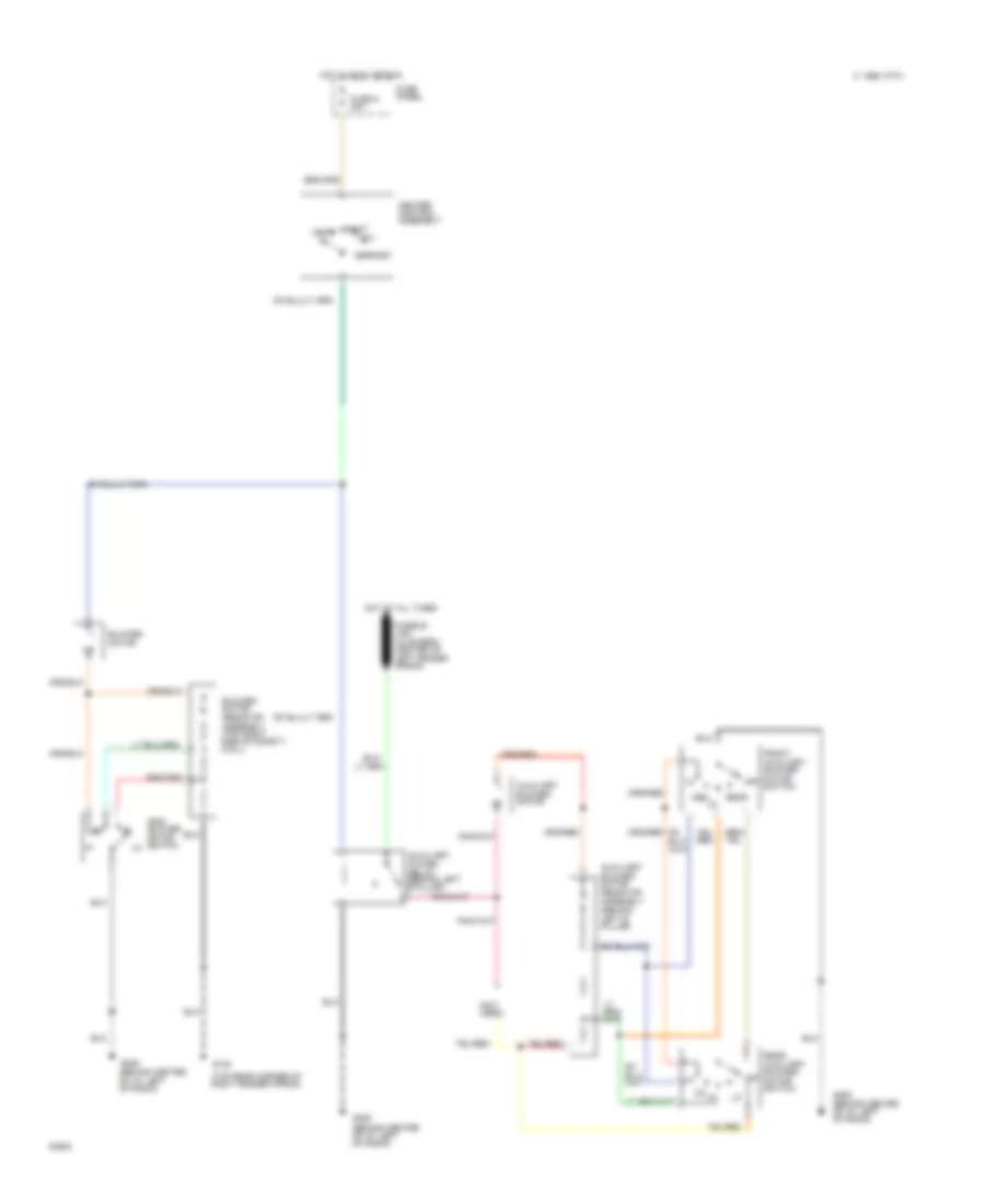
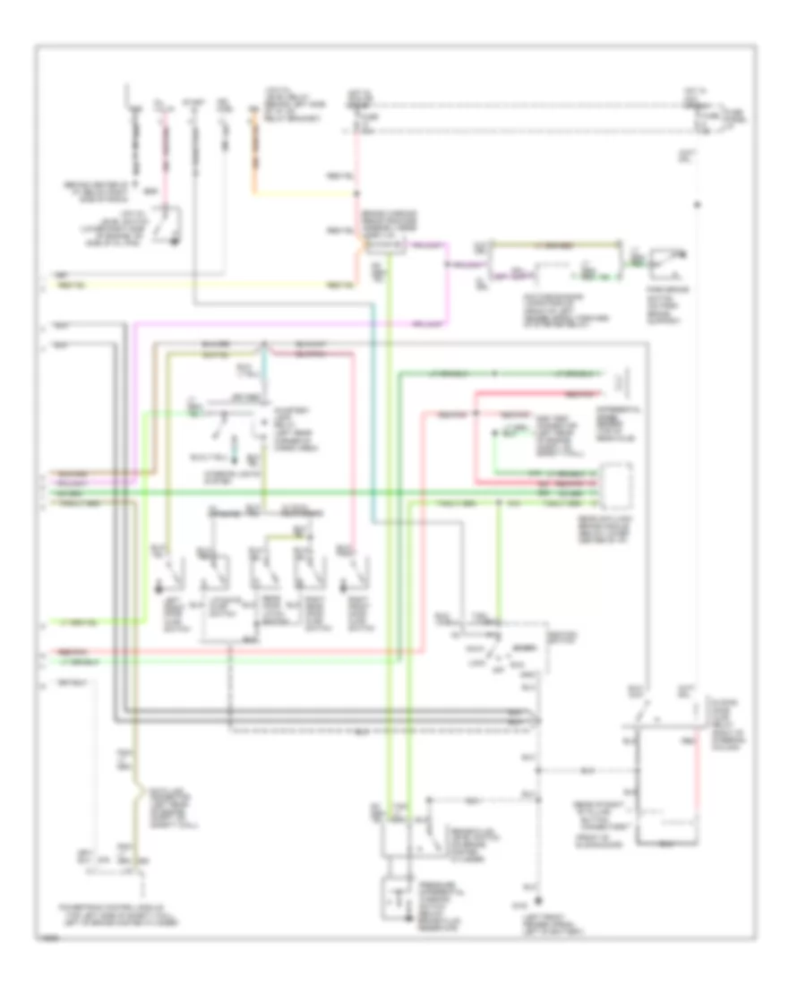
AIR CONDITIONING A/C Wiring Diagram for Ford Aerostar 1995 List of elements for A/C Wiring Diagram for Ford Aerostar 1995: 44 (3.0l) (4.0l) (lower left front of engine) (pcm power relay) (right rear of engine compartment on a/c accumulator) (top rear corner of right fender apron) (top rear corner of right fender apron) g100 A/c clutch diode A/c control assembly A/c clutch field coil A/c cutout relay (in engine compartment relay box ) Auxiliary a/c system refrigerant valve solenoid (behind left b pillar) Auxiliary blower motor Auxiliary blower motor resistor assembly (behind left b pillar) Auxiliary power relay (behind left b pillar) Blower motor Blower motor resistor assembly (top right side of safety wall) C 1995 vftc Clutch cycling pressure switch Def Defrost Floor Front auxiliary blower motor switch Fuse 6 20a Fuse 9 30a Fuse panel G105 G206 (behind center of i/p, left of radio) Heat High pressure cutoff switch (right front of engine) (3.0l) (left front of engine) (4.0l) Hot at all times Hot in accy or run Hot in run Main blower motor switch Max Med Mix Norm Off Power- train control module (top left side of safety wall) Rear Rear auxiliary blower motor switch Red Vent Heater Wiring Diagram for Ford Aerostar 1995 List of elements for Heater Wiring Diagram for Ford Aerostar 1995: 25 (not used) (top rear corner of right fender apron) Auxiliary blower motor Auxiliary blower motor resistor assembly (behind left b pillar) Auxiliary power relay (behind left b pillar) Blower motor Blower motor resistor assembly (top right side of safety wall) C 1995 vftc Defrost Front auxiliary blower motor switch Fuse 9 30a Fuse panel G105 G206 (behind center of i/p, left of radio) Heat Heater control assembly Hot at all times Hot in accy or run Main blower motor switch Med Mix Off Rear Rear auxiliary blower motor switch Vent
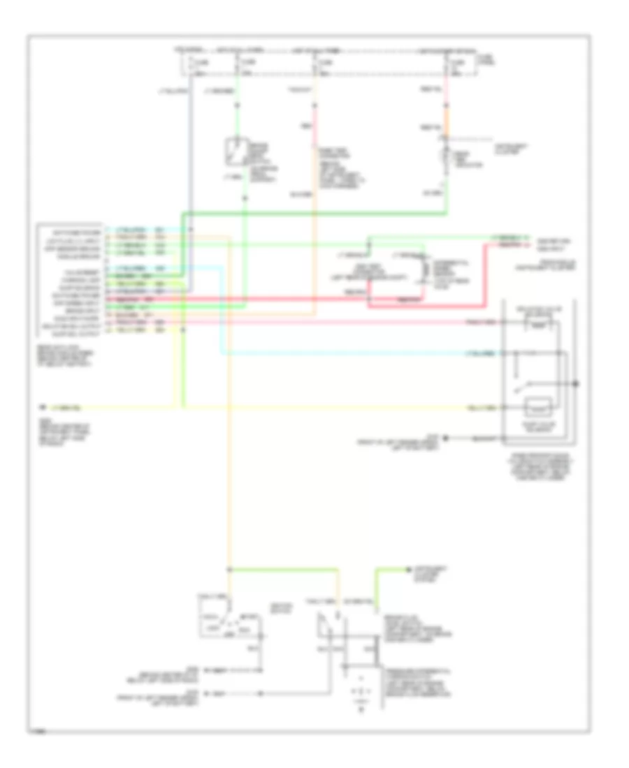
ANTI-LOCK BRAKES Anti-lock Brake Wiring Diagrams for Ford Aerostar 1995 List of elements for Anti-lock Brake Wiring Diagrams for Ford Aerostar 1995: 49 (behind left side of instrument panel, taped to main harness) (on brake pedal support) (top of rear axle) Acc Brake fluid level switch (left rear of engine compartment, on brake master cylinder) Brake input Brake on/off (boo) switch Diag input/kapr Diff sensor ground Diff speed input Differential speed sensor Dss input Dss return Dss test connector (left rear of engine compt) Dump sol output Dump solenoid Dump valve solenoid Fuse 15a Fuse 20a Fuse panel G100 (front of left fender apron, left of battery) G206 (behind center of instrument panel, below left side of radio) G206 (behind center of i/p, below left side of radio) Hot at all times Hot in run Hot in start or run Ignition switch Instrument cluster Instrument cluster system Isolation sol output Isolation valve solenoid Lock Low fluid lvl input Module ground Nca Off Pressure differential warning switch (left rear of engine compartment, below brake fluid reservoir) Psom module (instrument cluster) Rabs proportioning valve switch assembly (left rear of engine compartment, below master cylinder) Rabs test connector Rear abs indicator Rear anti-lock brake module (rabs) (behind center of i/p, below ashtray) Red Red/pnk Run Start Switched power Valve reset Warning lamp
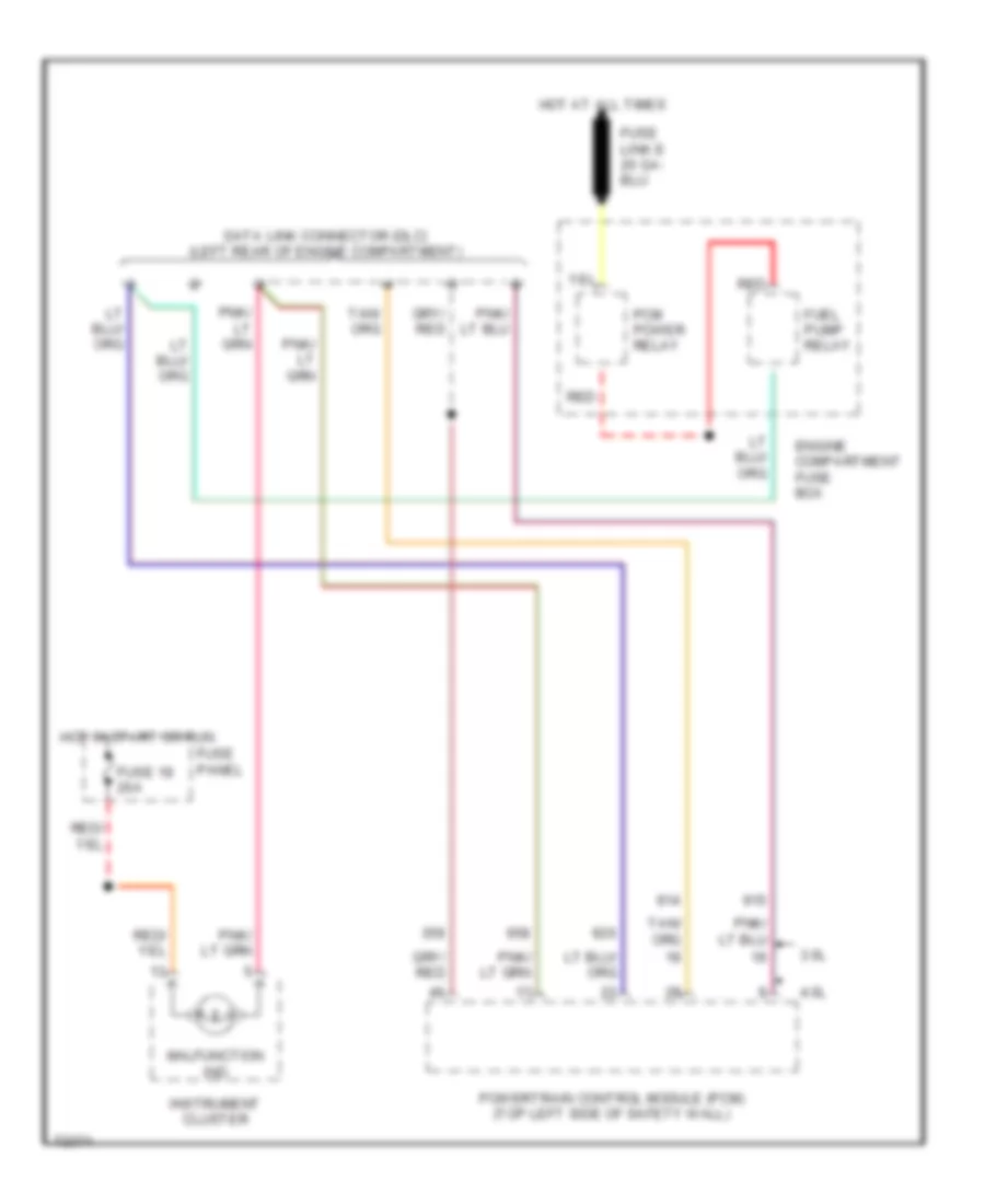
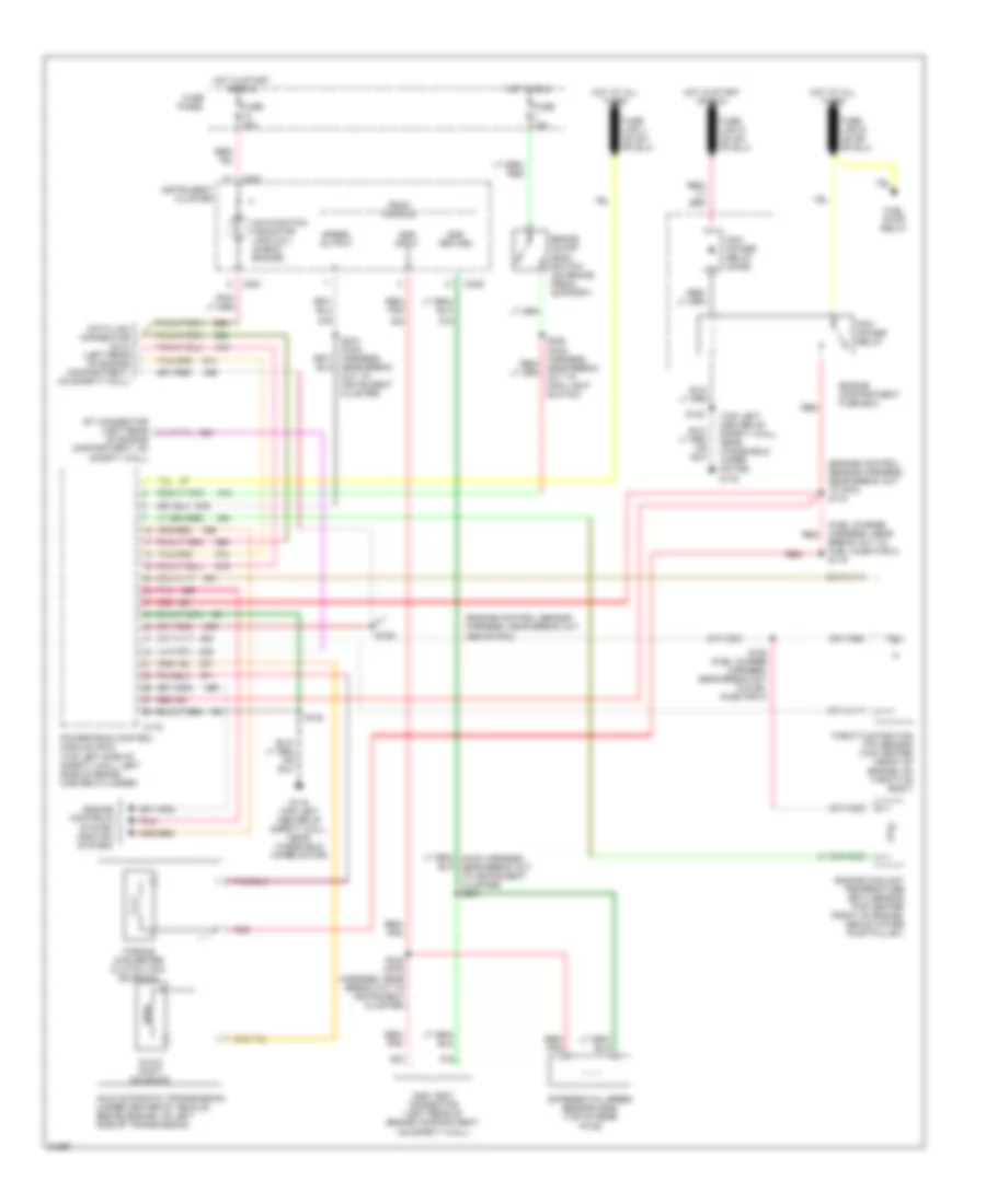
COMPUTER DATA LINES Computer Data Lines for Ford Aerostar 1995 List of elements for Computer Data Lines for Ford Aerostar 1995: 14 3.0l 4.0l Data link connector (dlc) (left rear of engine compartment) Engine compartment fuse box Fuel pump relay Fuse 18 20a Fuse panel Hot at all times Hot in start or run Instrument cluster Malfunction ind Pcm power relay Powertrain control module (pcm) (top left side of safety wall) Red
CRUISE CONTROL Cruise Control Wiring Diagram for Ford Aerostar 1995 List of elements for Cruise Control Wiring Diagram for Ford Aerostar 1995: 66 (behind center of i/p, (in steering wheel) (left rear corner of engine compartment) (on brake pedal support) 100- 40- 50,000 ohms Accel Actuator (connects to throttle linkage) Battery Below left side of radio) Below right side of radio) Brake input Brake on/off (boo) switch C249 Clock- spring assembly (inside steering column) Cntl sw input Coast Exterior lights system (multi-function switch) Fast Fuse 1 15a Fuse 12 30a Fuse 17 10a Fuse 6 20a Fuse 8 15a Fuse panel G206 Gnd Ground Horn relay (right side of steering column) Horns system Horns system Hot at all times Hot in accy or run Hot in run Ignition Instrument cluster Nca Off Ohms Pnk Pnk/ Psom module Red Red/ Resume Run Servo motor Servo posit feed Servo posit gnd Servo posit signal Set/ Slow Sol volt source Sol+ Speed output Speed control amplifier (right side of instrument panel, above cowl panel) Speed control servo Speed control switch assembly (partial) Speed input Vac Vac sol cntl Vacuum distribution Vacuum dump valve (vents to atmosphere when brake is depressed) Vent Vent sol cntl
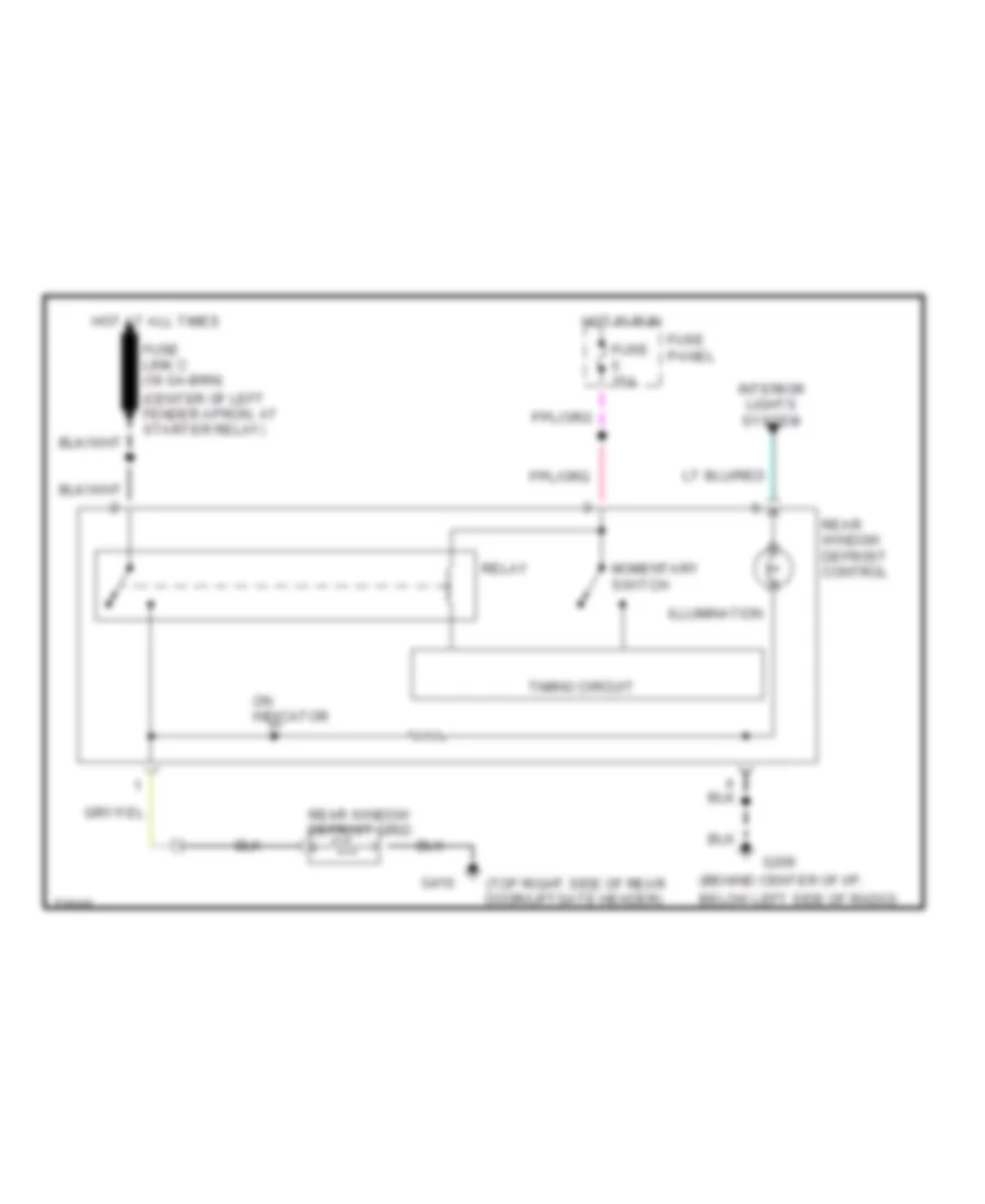
DEFOGGERS Defogger Wiring Diagram for Ford Aerostar 1995 List of elements for Defogger Wiring Diagram for Ford Aerostar 1995: 18 (behind center of i/p, (center of left fender apron, at starter relay) (top right side of rear door/liftgate header) Below left side of radio) Fuse 15a Fuse panel G206 G410 Hot at all times Hot in run Illumination Interior lights system Momentary switch On indicator Rear window defrost control Rear window defrost grid Relay Timing circuit
ENGINE PERFORMANCE
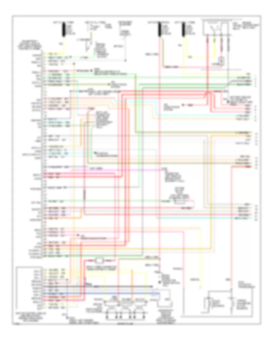
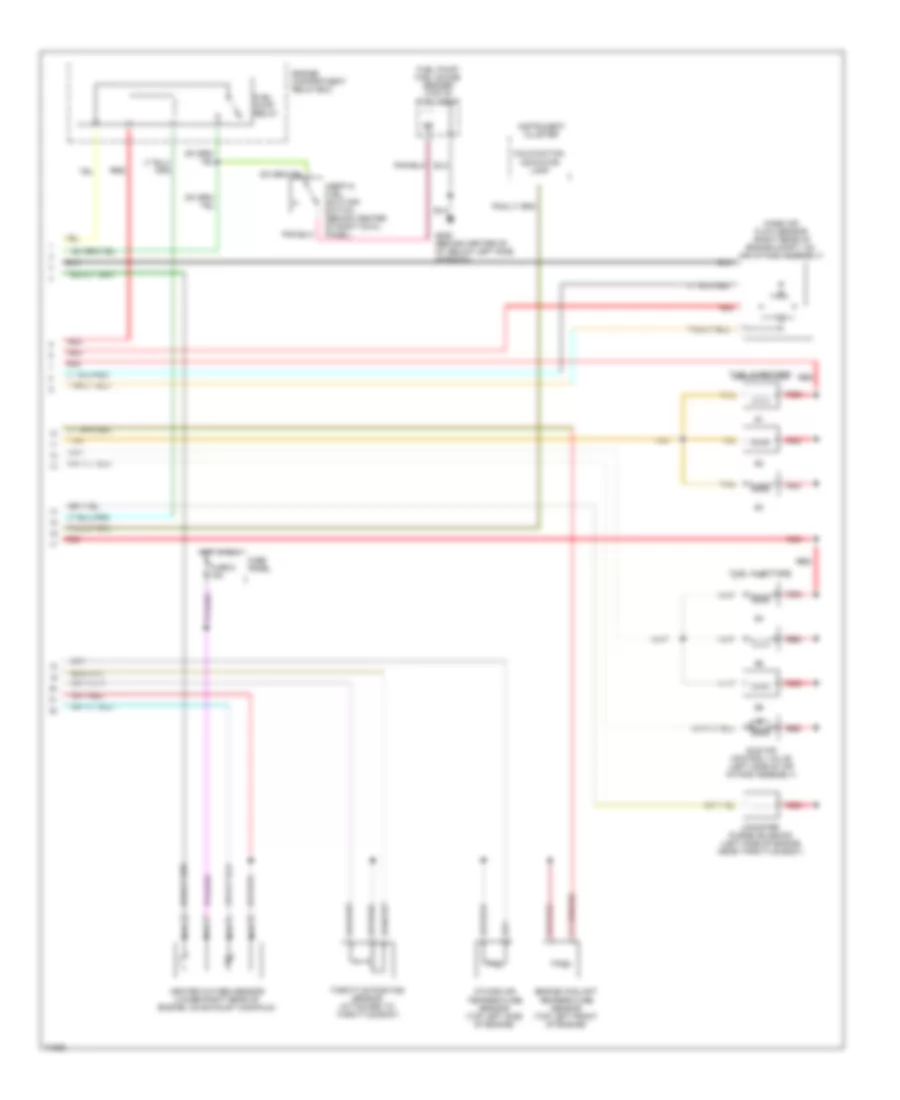
3.0L 3.0L, Engine Performance Wiring Diagrams (1 of 2) for Ford Aerostar 1995 List of elements for 3.0L, Engine Performance Wiring Diagrams (1 of 2) for Ford Aerostar 1995: 71 (not used) 3-4/4-3 shift solenoid A4ld automatic transmission Accs Air conditioning Air conditioning system Boo Brake on/off switch (behind steering column) C256 Canp Coil output Cse gnd Data (+) Data (-) Data link connector (right rear corner of engine compartment) Distributor Ect Engine compartment relay box Fpm Fuse 15a Fuse panel G100 (front left fender apron, left of battery) G206 (behind center of i/p, below right side of radio) H2os Hot at all times Hot in start or run Iac Iat Idm Ign gnd Ign pwr Ignition coil Ignition control module (icm) (center of right fender apron, near air cleaner) Inj 1 Inj 2 Inj 3 Inj 4 Inj 5 Inj 6 Instrument cluster Kapwr Maf Maf rtn Nca Pcm power relay Pcm power relay diode Pip Pnk Pnp Power distribution system Powertrain control module (pcm) (top left side of safety wall, left side of brake master cylinder) Psom (+) Psom (-) Pwr gnd Radio noise capacitor (top left rear of engine, near ignition coil) Red Sig rtn Spout Spout check connector (left rear of engine compartment, tape to engine control sensor harness, near master cylinder) Ss 3/4 Starting/ charging system Sti Sti connector (right rear corner of engine compartment) Sto/mil System Tan Tcc Torque converter clutch solenoid Vpwr Vref Wac 3.0L, Engine Performance Wiring Diagrams (2 of 2) for Ford Aerostar 1995 List of elements for 3.0L, Engine Performance Wiring Diagrams (2 of 2) for Ford Aerostar 1995: 29 (behind center of i/p, below left side of battery) C251 Canister purge solenoid (top left side of engine, below intake manifold) Cruise control system Engine compartment relay box Engine coolant temperature (ect) sensor (top center front of engine, above water pump pulley) Fuel injectors Fuel pump relay Fuel pump/ fuel gauge sender (below rear of vehicle, top of fuel tank) Fuse 18 15a Fuse 5 15a Fuse panel G117 (right rear of engine, near oil pressure switch) G206 Heated oxygen sensor (ho2s) (lower left rear of engine, on exhaust manifold) Hot at all times Hot in run Hot in run or start Idle air control valve (top left front of engine, left side of air air intake assembly) Inertia fuel shut-off switch (opens on impact) (behind center of right cowl panel) Instrument cluster Intake air temperature (iat) sensor (top left side of engine, behind idle air control valve) Malfunction indicator Mass air flow sensor (right rear of engine compartment, on air intake assembly) Nca Psom module Red Tan Throttle position (tp) sensor (top center front of engine, on throttle body)
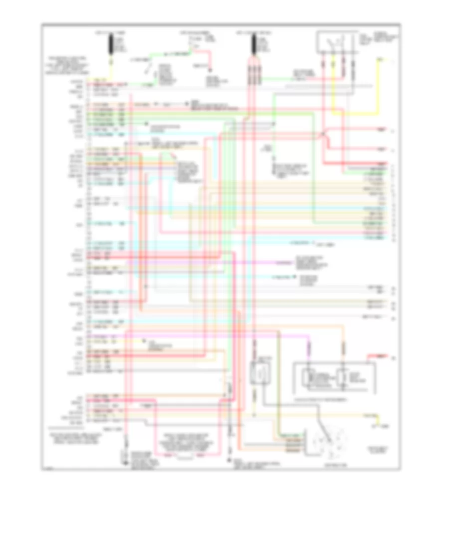
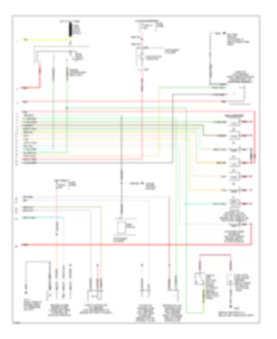
4.0L 4.0L, Engine Performance Wiring Diagrams (1 of 2) for Ford Aerostar 1995 List of elements for 4.0L, Engine Performance Wiring Diagrams (1 of 2) for Ford Aerostar 1995: 76 (not used) 3-4/4-3 shift solenoid A4ld automatic transmission Accs Air conditioning system Boo Brake on/off switch (behind steering column) C198 C199 Canp Ckp (+) Ckp (-) Coil 1 Coil 2 Coil 3 Cpp m/t-pnp a/t Crankshaft position sensor (lower right front of engine compartment) Cse gnd Data (+) Data (-) Data link connector (left rear of engine compartment on safety wall) Diode Ect Engine compartment relay box Fpm Fuse 1 15a Fuse panel G100 (front left fender apron, left of battery) G206 (behind center of i/p, below right side of radio) Ground Ho2s Ho2s gnd Hot at all times Hot start or run Iac Iat Idm Ign gnd Ign pwr Ignition coil (right side of valve cover) Ignition control module (center of right fender apron near air cleaner) Inj bank 1 Inj bank 2 Instrument cluster Kapwr Maf Maf rtn Nca Oct adj Octane adjust plug (top left rear of engine compt) Pcm power relay Pip Pnk Powertrain control module (left side of brake master cylinder) Psom (+) Psom (-) Pwr gnd Radio noise capacitor (near ignition coil) Red Shield Sig rtn Spark plugs Speed output Spout Spout check connector (near master cylinder) Ss3/4 Starting charging system Sti Sti connector (left rear of engine compt on safety wall) Sto/mil Tan Tcc Torque converter clutch solenoid Vpwr Vref Wac 4.0L, Engine Performance Wiring Diagrams (2 of 2) for Ford Aerostar 1995 List of elements for 4.0L, Engine Performance Wiring Diagrams (2 of 2) for Ford Aerostar 1995: 21 Canister purge solenoid (left side of engine near throttle body) Engine compartment relay box Engine coolant temperature sensor (top left front of engine) Fuel injectors Fuel pump relay Fuel pump/ fuel gauge sender (top of fuel tank) Fuse 5 15a Fuse panel G206 (behind center of i/p, below left side of radio) Heated oxygen sensor (lower right rear of engine, on exhaust manifold) Hot in run Idle air control valve (left side of air intake assembly) Inertia fuel shut-off switch (behind center of right cowl panel) Instrument cluster Intake air temperature sensor (top left side of engine) Malfunction indicator lamp Mass air flow sensor (right rear of engine compt, on air intake assembly) Nca Red Tan Throttle position sensor (attached to throttle body)
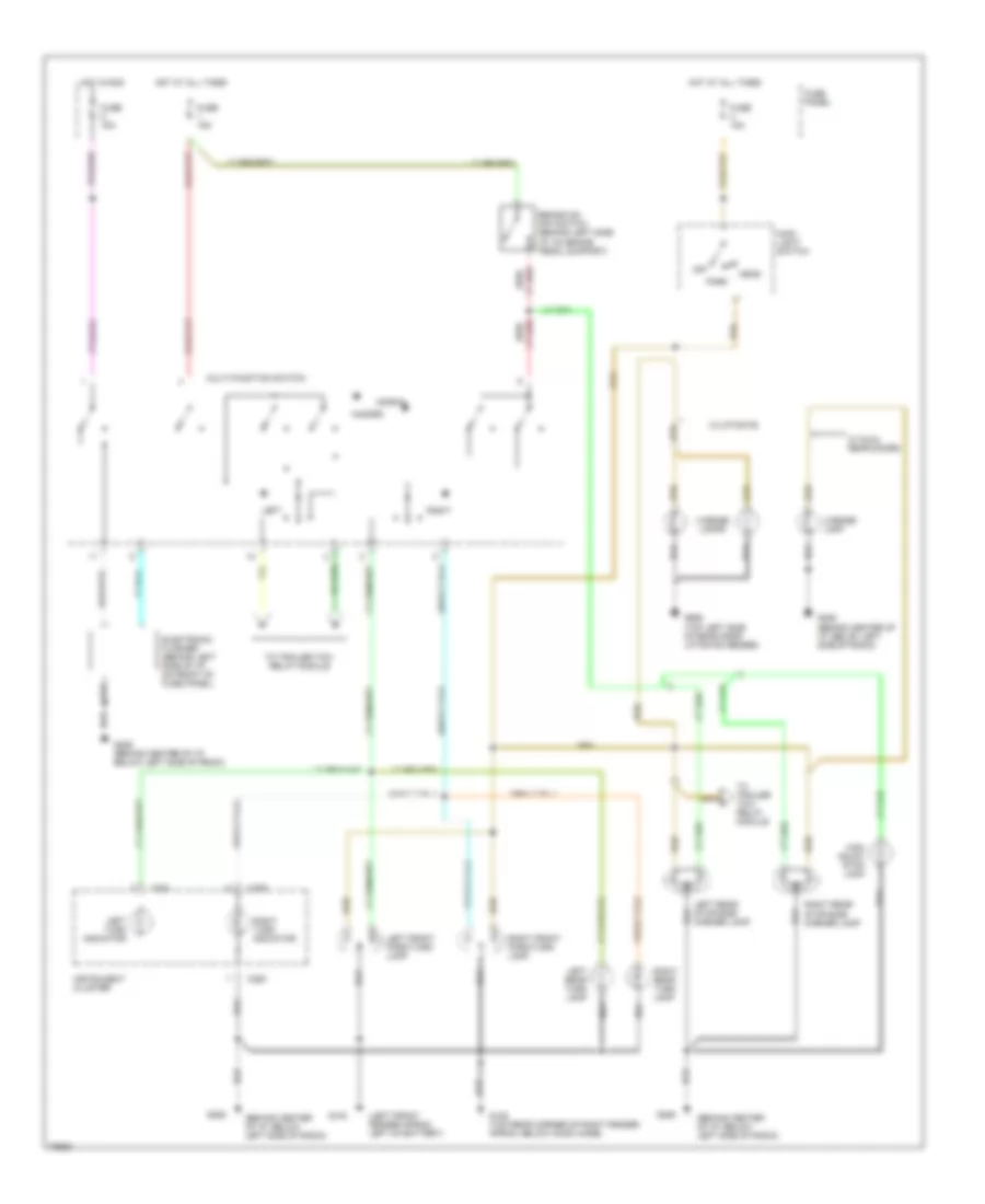
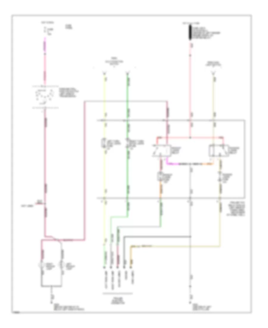
EXTERIOR LIGHTS Exterior Light Wiring Diagram (1 of 2) for Ford Aerostar 1995 List of elements for Exterior Light Wiring Diagram (1 of 2) for Ford Aerostar 1995: 41 (behind center of i/p, below left side of radio) (left front fender apron, left of battery) Brake on/ off switch (behind left side i/p, on brake pedal support) C250 C251 Electronic flasher (behind left side of i/p, on front of fuse panel) Fuse 15a Fuse panel G100 G105 (top rear corner of right fender apron, below hood hinge) G206 G206 (behind center of i/p, below left side of radio) G906 (top left side of rear door/ liftgate header) Hazard Head High mount stop lamp Hot at all times Hot in run Instrument cluster Lamp Left Left front park/turn lamp Left rear stop/side marker lamp Left rear turn lamp Left turn indicator License License lamps Main light switch Multi-function switch Normal Off Park Red/ Right Right front park/turn lamp Right rear stop/side marker lamp Right rear turn lamp Right turn indicator To trailer tow relay module W/ dual rear doors W/liftgate Exterior Light Wiring Diagram (2 of 2) for Ford Aerostar 1995 List of elements for Exterior Light Wiring Diagram (2 of 2) for Ford Aerostar 1995: 27 (not used) Backup lamps Backup lamps fuse 10a Backup lamps relay From From main light switch Fuse 15a Fuse panel G206 (behind center of i/p, below left side of radio) G402 (center of left side 'd' pillar) Ground Hot at all times Hot in run Left backup lamp Left turn lamp Left turn/ stop lamps fuse 3a Multi-function switch Park lamps Park/neutral position switch (left side of transmission) Red Right backup lamp Right turn lamp Right turn/ stop lamps fuse 3a Running lamps fuse 10a Running lamps relay Trailer electric connector Trailer tow relay module (left rear of cargo area, above rear of wheel well)
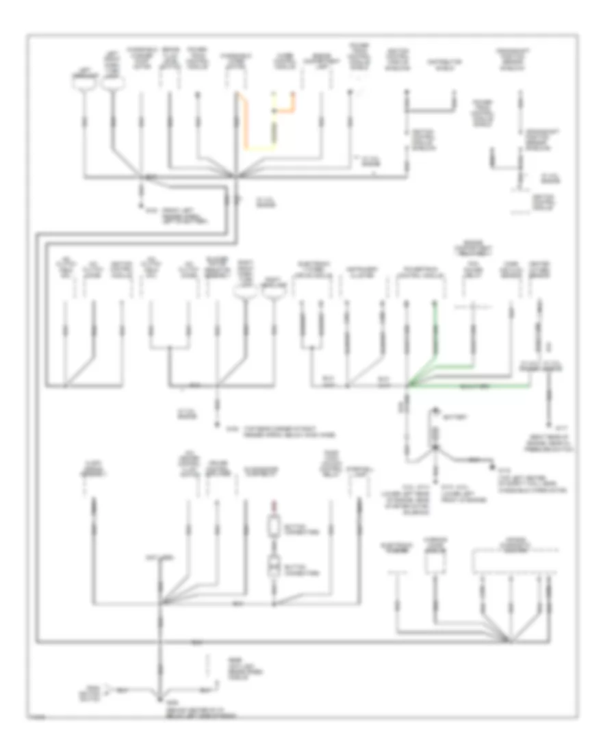
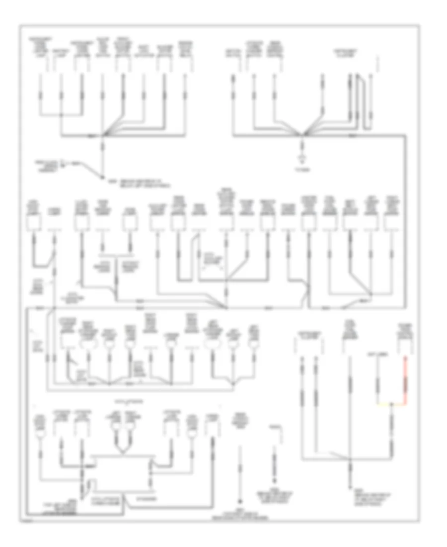
GROUND DISTRIBUTION Ground Distribution Wiring Diagram (1 of 2) for Ford Aerostar 1995 List of elements for Ground Distribution Wiring Diagram (1 of 2) for Ford Aerostar 1995: 71 (3.0l) (4.0l) (behind center of i/p, below left side of radio) (front left fender apron, left of battery) (lower left front of engine) (lower left rear of engine, near (not used) (right rear of engine, near oil (top left center of safety wall near, (top rear corner of right fender apron, below hood hinge) A/c clutch diode A/c clutch field coil A/c heater control illum- Air bag diagnostic monitor Battery Blower motor resistor assembly Brake fluid level switch Button connectors C232 C233 C250 C251 Clock spring assembly Crankshaft position sensor shield #1 Crankshaft position sensor shield #2 Cruise control amplifier Distributor shield Door lock/ unlock control relay Electronic 4 wheel drive module Electronic flasher Engine Engine compartment lamp Engine compartment relay box From ignition switch G100 G105 G110 G114 G116 G117 G206 Heated oxygen sensor Ignition control module Ignition control module shield #1 Ignition control module shield #2 Ination Instrument cluster Left front park/ turn lamp Left headlamp Mass air flow sensor Nca Pcm power relay Power- train control module Power- train control module shield Powertrain control module Pressure switch) Rear anti-lock brake (rabs) module Red Right front park/ turn lamp Right headlamp Sliding door ajar relay Starter motor/ solenoid) Stepwell lamp W/ 3.0l engine W/ 4.0l engine W/ 4.0l w/ 3.0l engine Warning chime module Windshield washer pump motor Windshield wiper motor Windshield wiper motor) Wiper control module Ground Distribution Wiring Diagram (2 of 2) for Ford Aerostar 1995 List of elements for Ground Distribution Wiring Diagram (2 of 2) for Ford Aerostar 1995: 72 (behind center of i/p, below left side of radio) (behind center of i/p, below right (not used) Ashtray lamp Auxiliary power relay Blower motor switch C249 C250 C255 Cargo lamp Dome and reading lamps Dome lamp Engine low oil level relay From clock spring assembly Front auxiliary blower motor switch Fuel pump/ fuel gauge sender G206 G206 (behind center of i/p, below right side of radio) G906 (top left side of rear door/ liftgate header) G907 (top right side of rear door/liftgate header) Glove box lamp and switch Gnd High mount stop lamp High mount stop lamp Ignition switch Illumi- nated entry timer Instrument cluster Instrument panel cigar lighter Instrument panel cigar lighter lamp Left backup lamp Left license lamp Left lumbar seat pump motor Left rear stop/side marker lamp Left rear turn lamp License lamp Liftgate ajar switch Liftgate washer pump motor Liftgate wiper motor Liftgate wiper/ washer switch Master window/ door lock switch Nca Power door lock module Power mirror switch Power- train control module Radio Rear auxiliary blower motor switch illumi- nation Rear cigar lighter Rear cigar lighter illumi- nation Rear window defrost control Rear window defrost grid Remote head- phone module Right backup lamp Right license lamp Right lumbar seat pump motor Right rear door ajar switch Right rear door latch switch Right rear stop/side marker lamp Right rear turn lamp Seat belt buckle switch Shift lock actuator Side of radio) Standard To g206 With auxiliary blower With dual rear doors With dual rear doors With illuminated entry With lift gate With liftgate With liftgate wiper/washer With reading lamps Without reading lamps
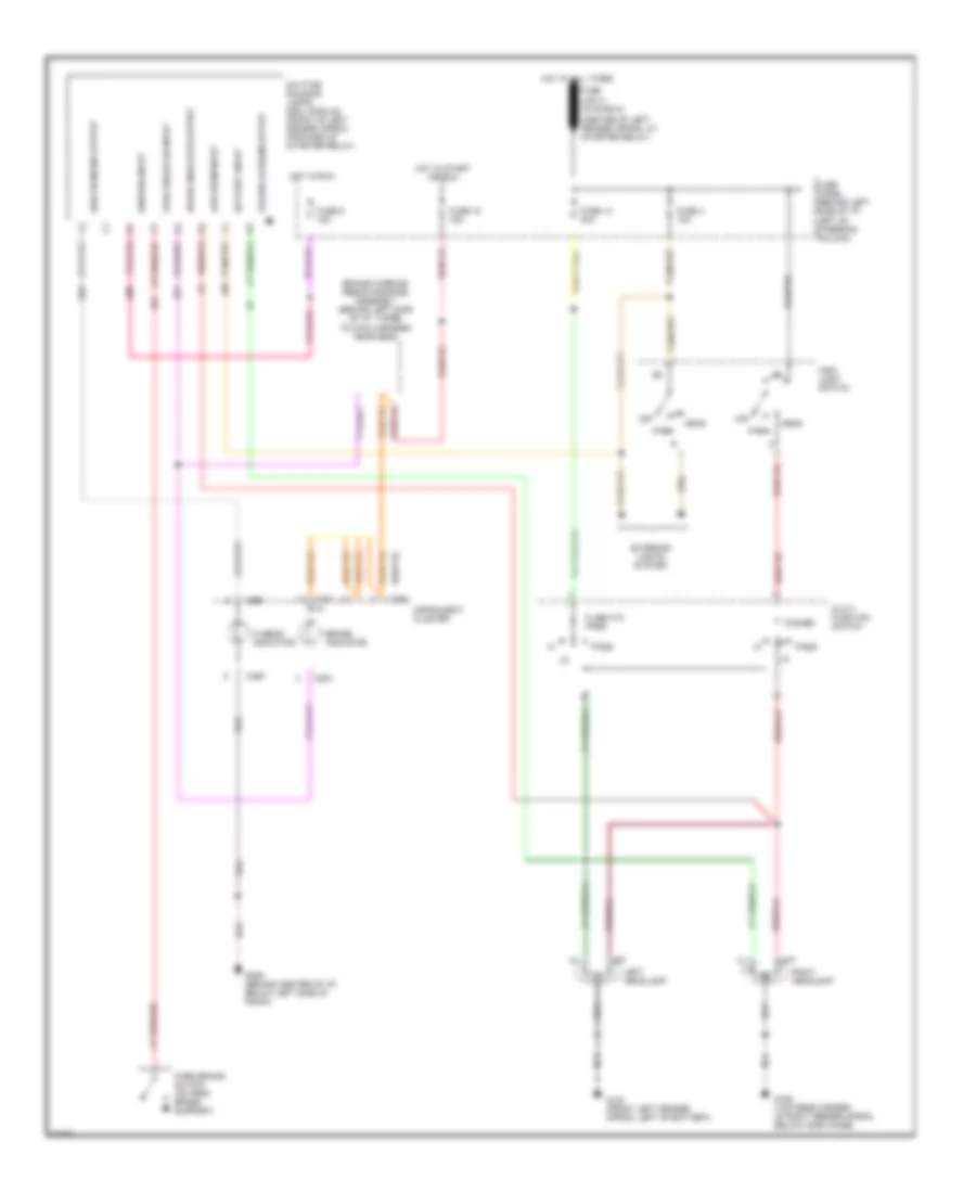
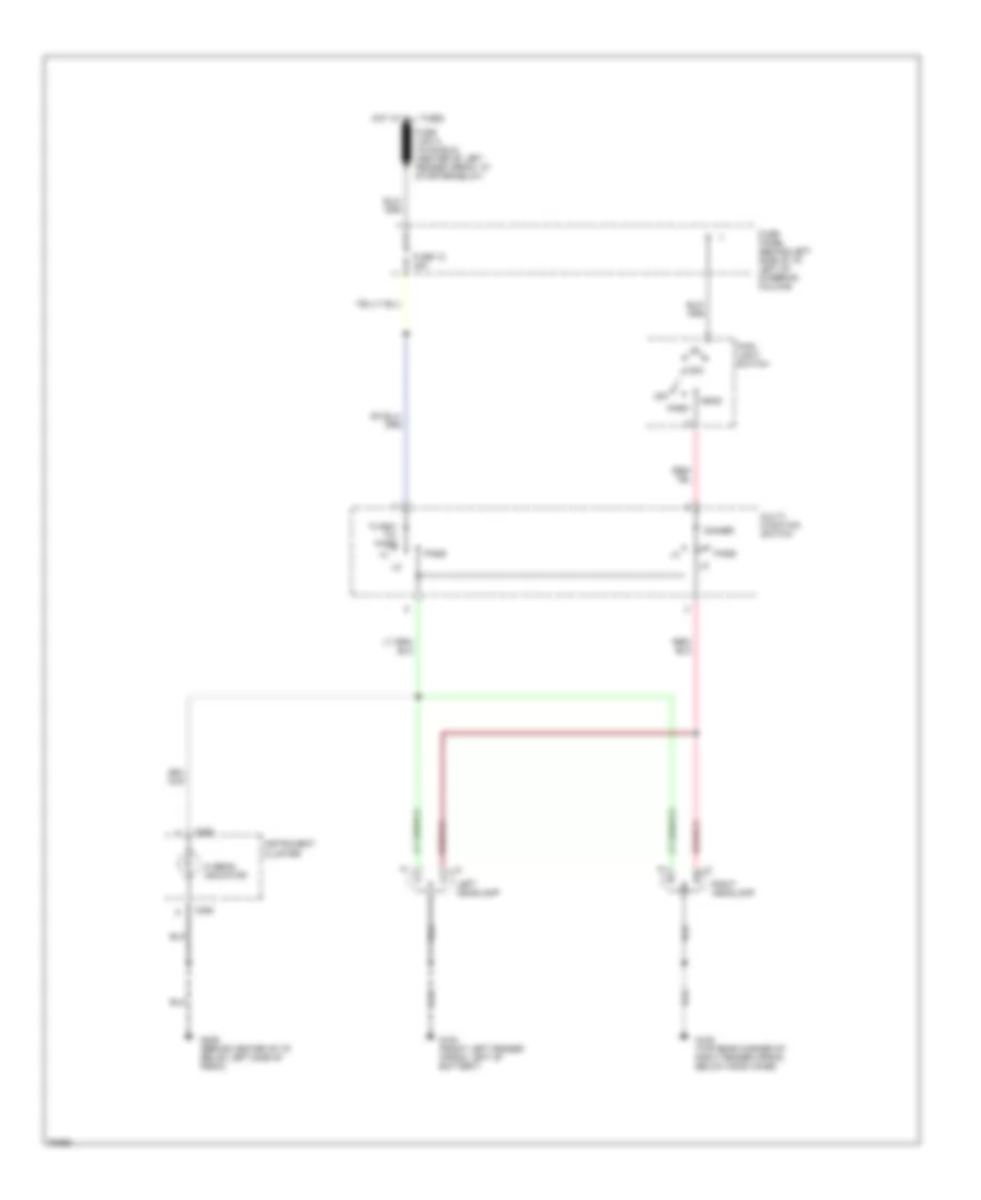
HEADLIGHTS Headlamps Wiring Diagram, with DRL for Ford Aerostar 1995 List of elements for Headlamps Wiring Diagram, with DRL for Ford Aerostar 1995: 38 (center of left fender apron, at starter relay) Battery input Brake indicator Brake indicator output Brake warning resistor/diode assembly (behind left side of i/p, taped to main harness near g206) C250 C251 Daytime running lamps (drl) module (front of left fender apron, forward of starter relay) Dimmer Exterior lights system Flash-to- pass Fuse 12 30a Fuse 18 15a Fuse 4 15a Fuse 5 15a Fuse panel (behind left side of i/p, left of steering column) G100 (front left fender apron, left of battery) G105 (top rear corner of right fender apron, below hood hinge) G206 (behind center of i/p, below left side of radio) Head Hi beam indicator High beam ind output Hot at all times Hot in run Hot in start or run Ignition input Instrument cluster Left headlamp Low beam input Main light switch Multi- function switch Off Park Park brake on input Park brake switch (on park brake support) Pass Pulsed hi beam output Right headlamp Headlamps Wiring Diagram, without DRL for Ford Aerostar 1995 List of elements for Headlamps Wiring Diagram, without DRL for Ford Aerostar 1995: 20 22a C250 Dimmer Flash- to- pass Fuse 12 30a Fuse panel (behind left side of i/p, left of steering column) G100 (front left fender apron, left of battery) G105 (top rear corner of right fender apron, below hood hinge) G206 (behind center of i/p, below left side of radio) Head Hi beam indicator Hot at all times Instrument cluster Left headlamp Main light switch Multi- function switch Off Park Pass Right headlamp
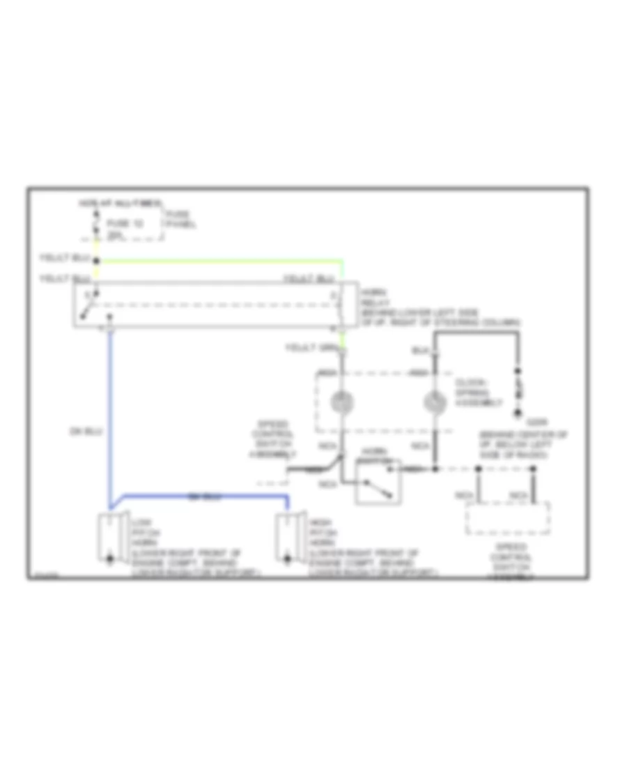
HORN Horn Wiring Diagram for Ford Aerostar 1995 List of elements for Horn Wiring Diagram for Ford Aerostar 1995: 13 (behind center of i/p, below left side of radio) 30a Clock- spring assembly Fuse 12 Fuse panel G206 High pitch horn (lower right front of engine compt, behind lower radiator support) Horn relay (behind lower left side of i/p, right of steering column) Horn switch Hot at all times Low pitch horn (lower right front of engine compt, behind lower radiator support) Nca Speed control switch assembly
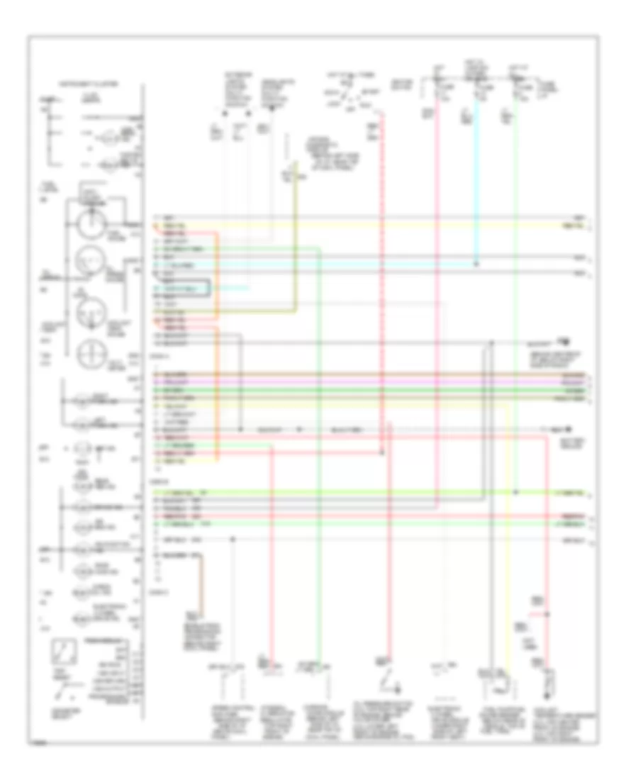
INSTRUMENT CLUSTER Instrument Cluster Wiring Diagram (1 of 2) for Ford Aerostar 1995 List of elements for Instrument Cluster Wiring Diagram (1 of 2) for Ford Aerostar 1995: 100 (behind center of i/p, below right side of radio) (behind left side of i/p, near top (behind left side of i/p, near top of (behind right (below rear of vehicle, top of (not 4 wheel A10 A11 A12 A13 A14 Acc Air bag Air bag ind. Alternator Amp ind. Amplifier Anti- slosh module B10 B11 B12 B13 Bat Battery ground Brake ind. Check oil ind. Chime module Conn a Conn b Conn c Coolant temp. Coolant temp. gauge Coolant temperature sender (3.0l-top center front of engine) (4.0l-top right front of engine) Cowl panel) Diagnostic Door ajar ind. Drive module (under right side of left Electronic Electronic 4 wheel drive ind. Enable Enable psom programming connector (behind right cowl panel) Engine) Exterior lights system (multi- function switch) Fasten belts ind. Front of Front seat) Fuel gauge Fuel level Fuel pump/fuel Fuel tank) Fuse 10a Fuse 15a Fuse 5a Fuse panel: i/p G206 Gauge sender Gnd Headlights system (multi- function switch) High beam ind. Hot at all times Hot in run Hot w/ lamp sw in park or head Ign Ign (run) Ignition switch Illum. Illum. lamps Instrument cluster Integral Left turn ind. Lock Malfunction ind. Module Odometer select Of cowl panel) Off Ohms Oil press. Oil press. gauge Oil pressure switch (3.0l-top right rear of engine, behind valve cover) (4.0l-lower left front of engine, above engine oil pan) Panel) Programming Psom module Rear abs ind. Red/ lt Red/pnk Regulator (top right Right turn ind. Run Side of i/p, above cowl Speed control Start Trip reset Used) Volt- meter Vss input Vss output Vss return Warning Instrument Cluster Wiring Diagram (2 of 2) for Ford Aerostar 1995 List of elements for Instrument Cluster Wiring Diagram (2 of 2) for Ford Aerostar 1995: 57 "b" pillar) (69db- (behind center of i/p, below right side of radio) (front of sliding door) (left front fender apron, left of battery) (left rear corner of cargo area) (lower right side (rear of right (top left side of safety wall, Acc Brake fluid level switch (on brake master cylinder) Button connectors Courtesy lamp relay Data link connector (left rear of engine compt, on safety wall) Daytime running lamps module (front of left fender apron, forward of starter relay) Differential speed sensor (top of rear axle) Dss test connector (left rear of engine compt, on safety wall) Fuse Fuse 15a Fuse panel: i/p G100 G206 Gnd Hot in acc or run Hot in run or start Ign Ignition switch Ind. ctrl Interior lights system Left front door ajar switch Left of brake master cylinder) Level switch Liftgate ajar switch Lock Low oil Low oil level relay (behind left side of i/p, on relay bracket) Of engine, on Off Oil lvl in Park brake Powertrain control module Pressure differential warning switch (below brake fluid reservoir) Rear anti-lock brake module (below lower center of i/p) Rear door latch switch Red Red/pnk Right front door ajar switch Right rear door ajar switch Run Side of oil pan) Sliding door ajar relay (right of steering column) Start Switch (on park brake support) W/ drl W/ dual rear doors W/ liftgate W/o drl
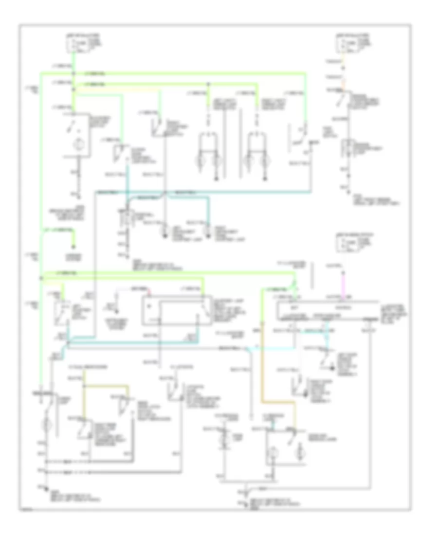
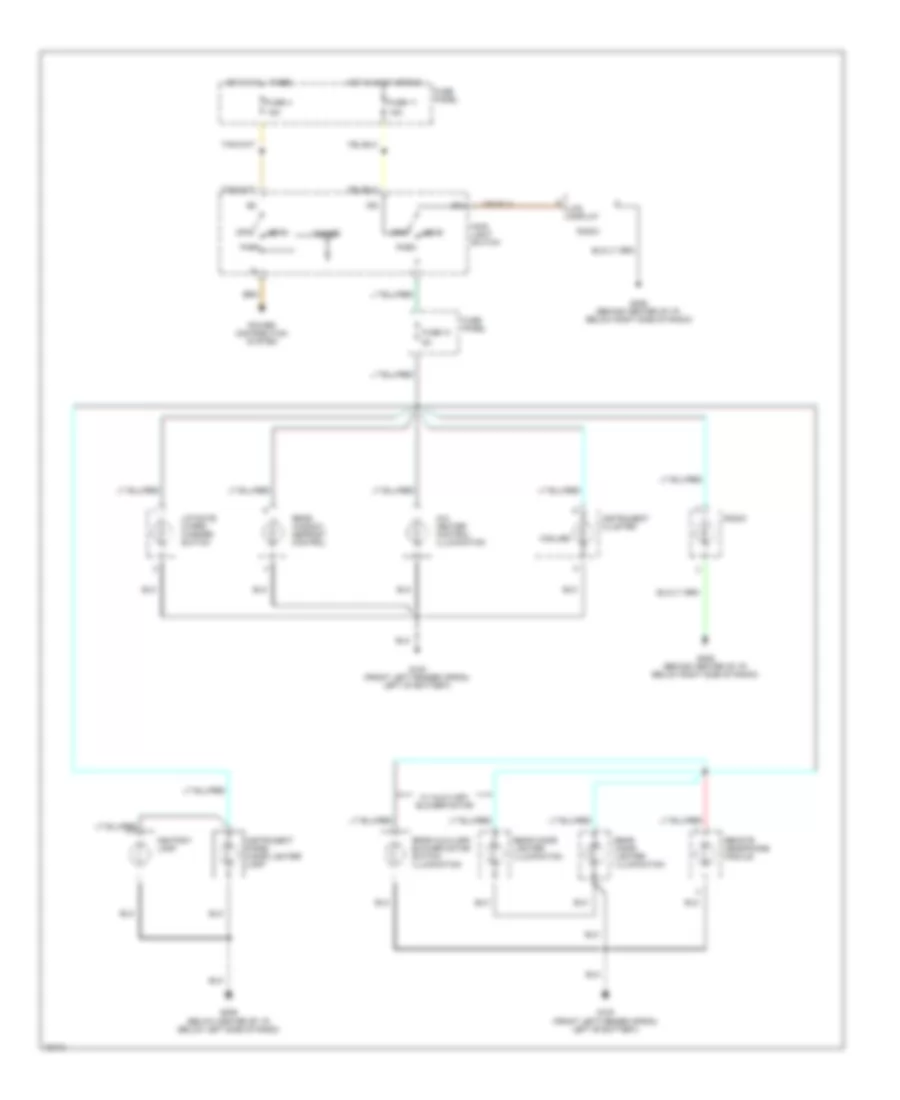
INTERIOR LIGHTS Courtesy Lamp Wiring Diagram for Ford Aerostar 1995 List of elements for Courtesy Lamp Wiring Diagram for Ford Aerostar 1995: 46 (below center of i/p, below left side of radio) g206 Acc/run Bat Cargo lamp Courtesy lamp relay (front of left "d" pillar, above rear lamps grommet) Dome Dome and reading lamps Dome lamp Door handles input Engine compartment lamp Engine compartment lamp mercury switch Fuse 15a Fuse 20a Fuse panel: i/p G100 (left front fender apron, left of battery) G206 (behind center of i/p, below left side of radio) G206 (below center of i/p, below left side of radio) Glove box lamp and switch Ground Hot at all times Hot in accy or run Illuminated entry output Illuminated entry timer (center rear of left "b" pillar) Instrument clusters system Left courtesy lamp switch Left door handle switch (on top of latch assembly) Left instrument panel courtesy lamp Left vanity mirror lamp and switch Liftgate ajar switch (in lower center of liftgate, on latch assembly) Main light switch Mirrors system Nca Off Rear door latch switch (in top of right rear door) Right courtesy lamp switch Right door handle switch (on top of latch assembly) Right instrument panel courtesy lamp Right rear door ajar switch (in lower left corner of right rear door) Right vanity mirror lamp and switch Sliding door courtesy lamp switch Stepwell lamp W/ dual rear doors W/ illuminated entry W/ liftgate W/ reading lamps W/o reading lamps Instrument Illumination Wiring Diagram for Ford Aerostar 1995 List of elements for Instrument Illumination Wiring Diagram for Ford Aerostar 1995: 30 15a 5 bulbs A/c- heater control illumination Ashtray lamp Dimmer Fuse 11 Fuse 13 Fuse 4 Fuse panel G100 (front left fender apron, left of battery) G206 (behind center of i/p, below right side of radio) G206 (below center of i/p, below left side of radio) Head Hot at all times Hot in accy or run Ign Instrument cluster Instrument panel cigar lighter lamp Lcd display Liftgate wiper/ washer switch Main light switch Off Park Power distribution system Radio Rear auxiliary blower motor switch illumination Rear cigar lighter illumination Rear window defrost control Remote headphone module W/ auxiliary blower motor
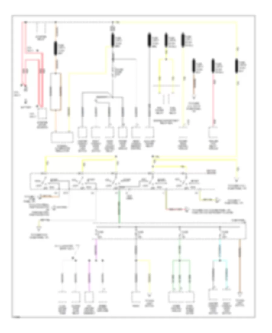
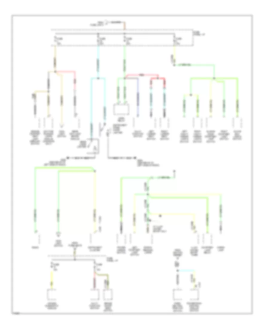
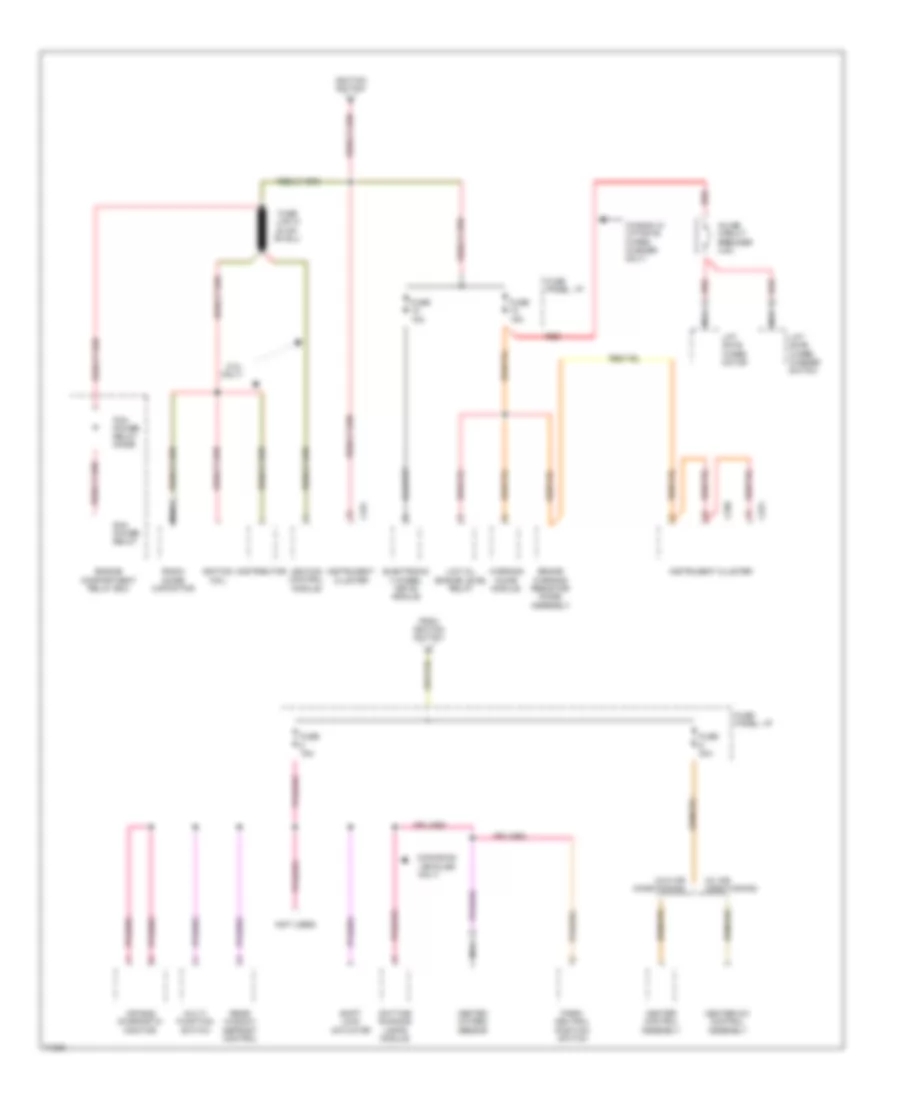
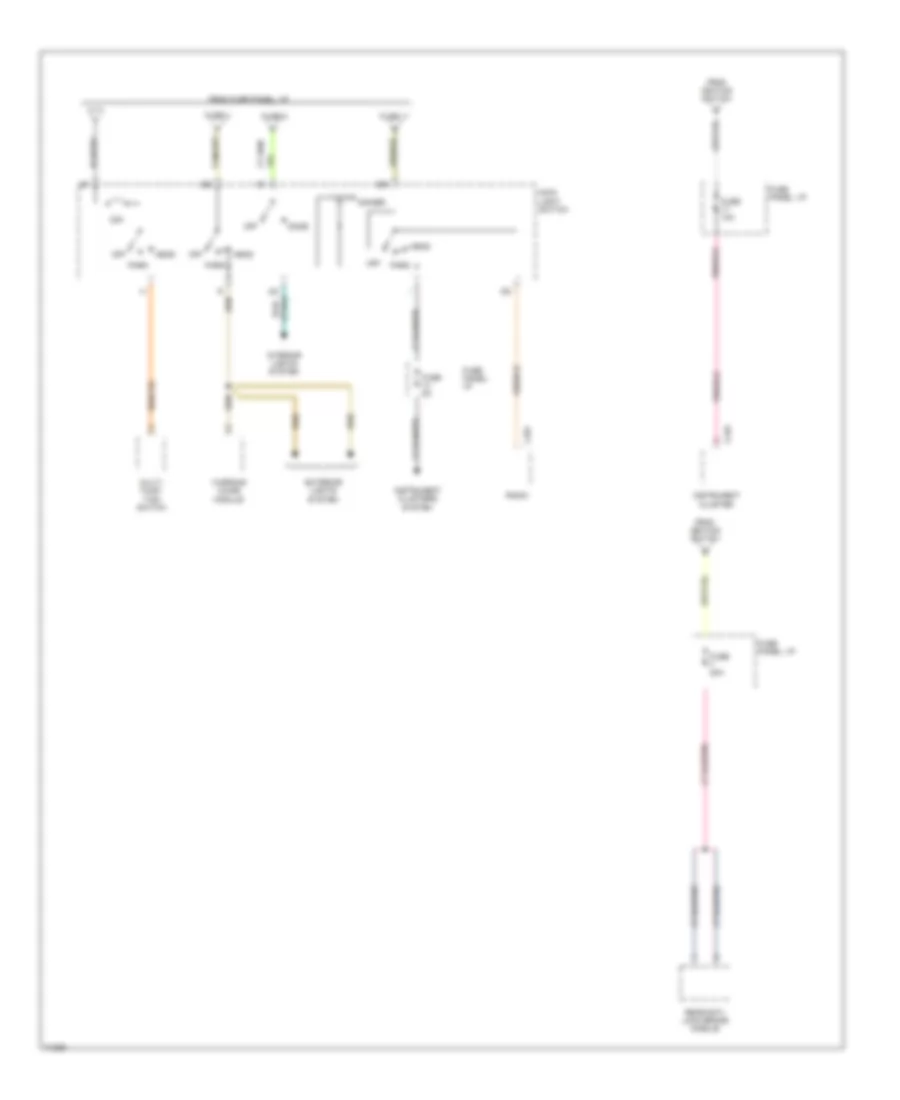
POWER DISTRIBUTION Power Distribution Wiring Diagram (1 of 4) for Ford Aerostar 1995 List of elements for Power Distribution Wiring Diagram (1 of 4) for Ford Aerostar 1995: 63 (3.0l (4.0l (fuse panel: i/p) (not used) (w/ illuminated 12 ga- 16 ga- 18 ga- 20 ga- A/c- heater control assembly Acc Auxiliary power relay Battery C172 Door lock/ unlock control relay Engine compartment relay box Entry only) Fuel pump relay Fuse 15a Fuse 20a Fuse 6a Fuse link a Fuse link b Fuse link c Fuse link d Fuse link e Fuse link f Fuse link j Fuse link k Fuse panel: i/p Ignition switch Illum- inated entry timer Inline fuse 30a Integral alternator regulator Lock Master window/ door lock switch Off Only) Pcm power relay Power door lock module Power- train control module Radio Rear window defrost control Red Right window/ door lock switch Run Sliding door ajar relay Speed control amplifier Sta Start Starter motor/ solenoid Starter relay To clutch pedal position switch or park/neutral position switch To fuse 17 (fuse panel: i/p) To fuse 7 (fuse panel: i/p) To fuses 10 & 1 (fuse panel: i/p) To fuses 15 & 18 (fuse panel: i/p), fuse link g & instrument cluster To fuses 4, 8, 12 & 16 To fuses 5 & 9 (fuse panel: i/p) To main light switch Trailer tow relay module Wind- shield wiper motor Wiper control module Power Distribution Wiring Diagram (2 of 4) for Ford Aerostar 1995 List of elements for Power Distribution Wiring Diagram (2 of 4) for Ford Aerostar 1995: 41 ** c254 Air bag diagnostic module Brake on/off (boo) switch C172 C249 Cargo lamp Courtesy lamp relay Daytime running lamps module (canadian only) Dome & reading lamps Engine compart- ment lamp mercury switch From a fuse link a From fuse link b From ignition switch Fuse 15a Fuse 20a Fuse 30a Fuse panel: i/p G206 (center of i/p, left side of radio) Glove box lamp & switch Horn relay Illum- inated entry timer Instrument cluster Instrument panel cigar lighter Left courtesy lamp switch Left lumbar seat switch Left vanity mirror lamp & switch Main light switch Multi- function switch Nca Park/ neutral position switch Power mirror switch Powertrain control module switch Radio Rear anti-lock brake module Rear cigar lighter Red Right courtesy lamp switch Right lumbar seat switch Right vanity mirror lamp & switch Sliding door courtesy lamp switch W/ illum- inated entry only Power Distribution Wiring Diagram (3 of 4) for Ford Aerostar 1995 List of elements for Power Distribution Wiring Diagram (3 of 4) for Ford Aerostar 1995: 40 (3.0l only) (canadian vehicles (not used) (w/ air conditioning) (w/o air conditioning) (wagon w/ liftgate wiper/ washer only) Air bag diagnostic monitor Brake warning resistor/ diode assembly C250 C251 Daytime running lamps module Distributor Electronic 4 wheel drive module Engine compartment relay box From ignition switch Fuse 15a Fuse 30a Fuse panel: i/p Heated oxygen sensor Heater control assembly Heater-a/c control assembly Ignition coil Ignition control module Ignition switch Inline circuit breaker 4.5a Instrument cluster Lift gate wiper motor Lift gate wiper/ washer switch Low oil engine level relay Multi- function switch Nca Only) Park/ neutral position switch Pcm power relay Pcm power relay diode Radio noise capacitor Rear window defrost control Red Shift lock actuator Warning chime module Power Distribution Wiring Diagram (4 of 4) for Ford Aerostar 1995 List of elements for Power Distribution Wiring Diagram (4 of 4) for Ford Aerostar 1995: 27 22a C249 C257 Dimmer Dome Exterior lights system From fuse panel: i/p From ignition switch Fuse 10a Fuse 11 Fuse 20a Fuse 4 Fuse 5a Fuse 8 Fuse panel: i/p Head Ign Instrument cluster Instrument clusters system Interior lights system Main light switch Multi- func- tion switch Off Park Radio Rear anti- lock brake module Warning chime module
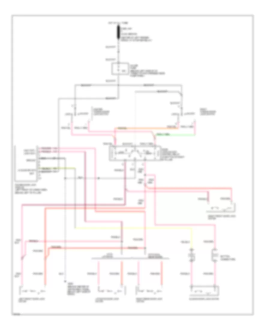
POWER DOOR LOCKS Power Door Lock Wiring Diagram for Ford Aerostar 1995 List of elements for Power Door Lock Wiring Diagram for Ford Aerostar 1995: 36 "b" pillar) (18 ga -brown) (behind center of (behind left side of i/p, taped to main harness near fuse panel) (center of left fender (in bottom of right 30a Apron, at starter relay) Bat Behind left "b" pillar) Button Connectors Door lock/unlock control relay Fuse link c G206 Ground Hot at all times In-line fuse Instrument panel, below left side of radio) Left front door lock motor Liftgate door lock motor Lk sldg dr cntl Lock Lock cntl Master window/door lock switch Pnk/ Power door lock module (left front of cargo area, Right front door lock motor Right rear door lock motor Right window/door lock switch Sliding door lock motor Un- lock Unlk cntl Unlock With dual rear doors With liftgate
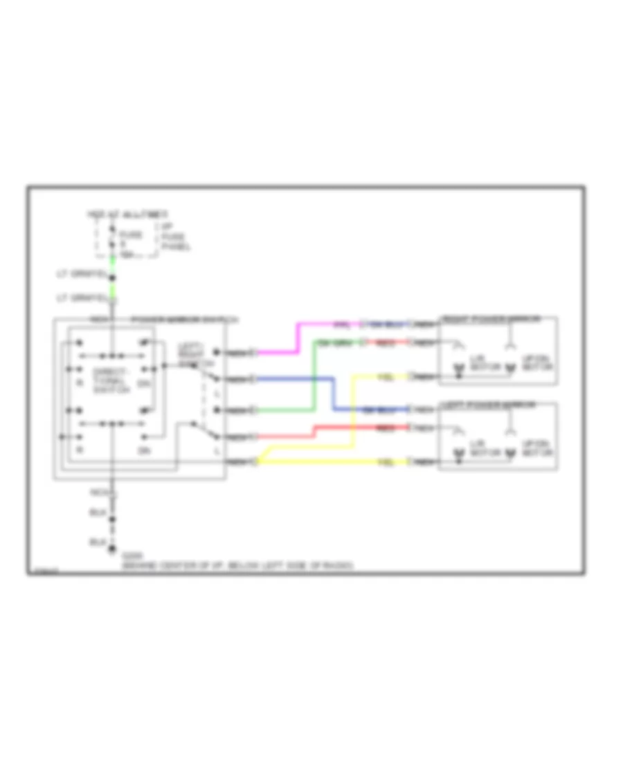
POWER MIRRORS Power Mirror Wiring Diagram for Ford Aerostar 1995 List of elements for Power Mirror Wiring Diagram for Ford Aerostar 1995: 13 Direct- tional switch Fuse 15a G200 (behind center of i/p, below left side of radio) Hot at all times I/p fuse panel L/r motor Left power mirror nca Left/ right switch Nca Power mirror switch Red Right power mirror nca Up/dn motor
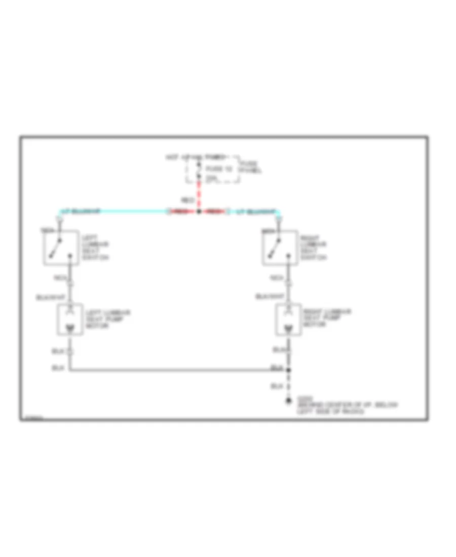
POWER SEATS Lumbar Wiring Diagram for Ford Aerostar 1995 List of elements for Lumbar Wiring Diagram for Ford Aerostar 1995: 11 30a Fuse 12 Fuse panel G202 (behind center of i/p, below left side of radio) Hot at all times Left lumbar seat switch Left lumbar seat pump motor Nca Red Right lumbar seat pump motor Right lumbar seat switch
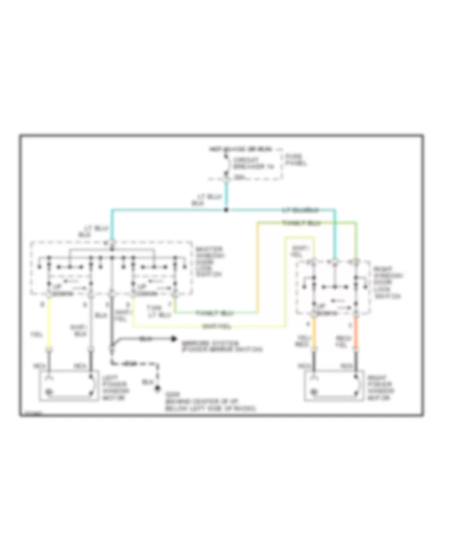
POWER WINDOWS Power Window Wiring Diagram for Ford Aerostar 1995 List of elements for Power Window Wiring Diagram for Ford Aerostar 1995: 13 20a Circuit breaker 14 Fuse panel G206 (behind center of i/p, below left side of radio) Hot in acc or run Left power window motor Master window/ door lock switch Mirrors system (power mirror switch) Nca Right power window motor Right window/ door lock switch Tan/ Up down
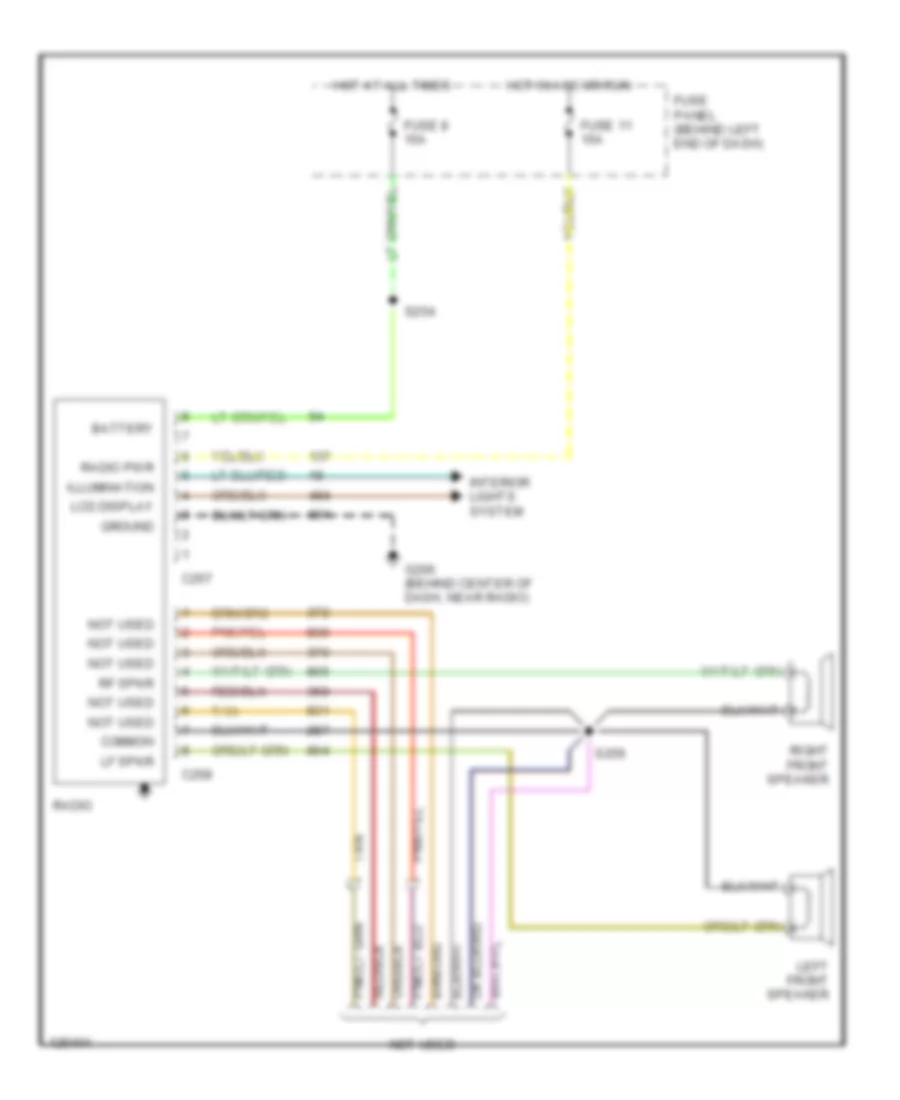
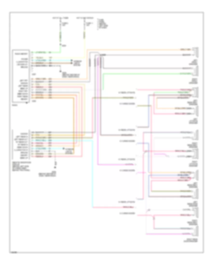
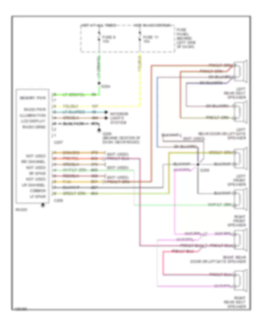
RADIO AM Radio Wiring Diagram for Ford Aerostar 1995 List of elements for AM Radio Wiring Diagram for Ford Aerostar 1995: 24 Battery C257 C258 Common Fuse 11 15a Fuse 8 15a Fuse panel (behind left end of dash) G206 (behind center of dash, near radio) Ground Hot at all times Hot in acc or run Illumination Interior lights system Lcd display Left front speaker Lf spkr Not used Radio Radio pwr Rf spkr Right front speaker S254 S259 Tan AM/FM Stereo, with Remote Headphones for Ford Aerostar 1995 List of elements for AM/FM Stereo, with Remote Headphones for Ford Aerostar 1995: 43 C257 C258 Common Fuse 11 15a Fuse 8 15a Fuse panel (behind left side of dash) G206 (behind center of dash, near radio) Ground Hot at all times Hot in acc or run Illumination Illumination in Interior lights system Lcd display Left front speaker Left frt Left liftgate speaker Left rear Left rear door speaker Left rear in Left rear out Left rear seat speaker Memory Nca Power Radio Radio memory Remote headphone module (behind left side of cargo area, behind trim panel) Right front speaker Right frt Right liftgate speaker Right rear Right rear door speaker Right rear seat speaker Rt rear in Rt rear out S254 S259 Seek down Seek up Tan W/ cargo doors W/ rear liftgate AM/FM Stereo, without Remote Headphones for Ford Aerostar 1995 List of elements for AM/FM Stereo, without Remote Headphones for Ford Aerostar 1995: 30 (not used) C257 C258 Common Fuse 11 15a Fuse 8 15a Fuse panel (behind left side of dash) G206 (behind center of dash, near radio) Hot at all times Hot in acc or run Illumination Interior lights system Lcd display Left front speaker Left rear door or liftgate speaker Left rear seat speaker Lf spkr Lr channel Memory pwr Not used Radio Radio pwr Rf spkr Right front speaker Right rear door or liftgate speaker Right rear seat speaker Rr channel S254 S259 Tan
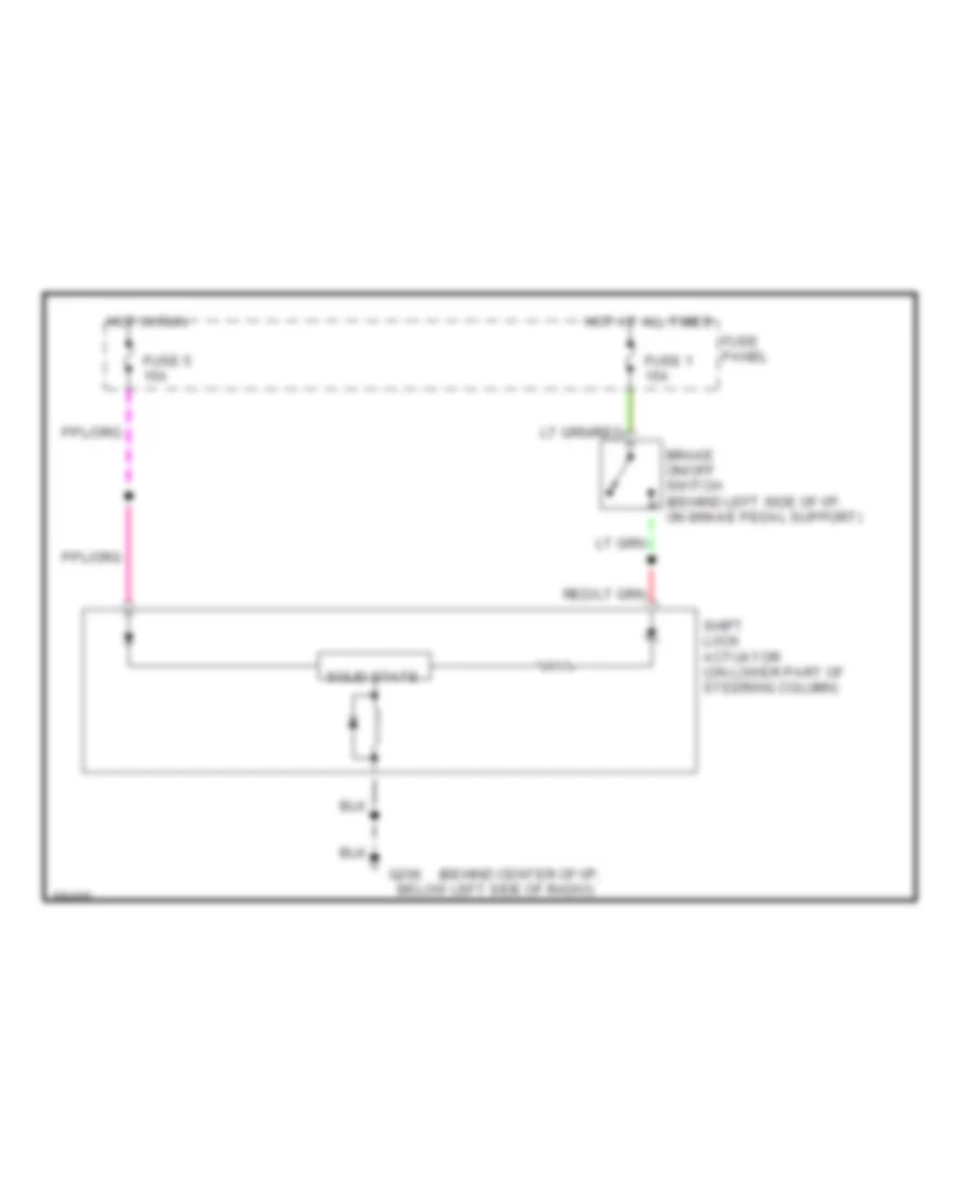
SHIFT INTERLOCKS Shift Interlock Wiring Diagram for Ford Aerostar 1995 List of elements for Shift Interlock Wiring Diagram for Ford Aerostar 1995: 11 (behind center of i/p, Below left side of radio) Brake on/off switch (behind left side of i/p, on brake pedal support) Fuse 1 15a Fuse 5 15a Fuse panel G206 Hot at all times Hot in run Shift lock actuator (on lower part of steering column) Solid state
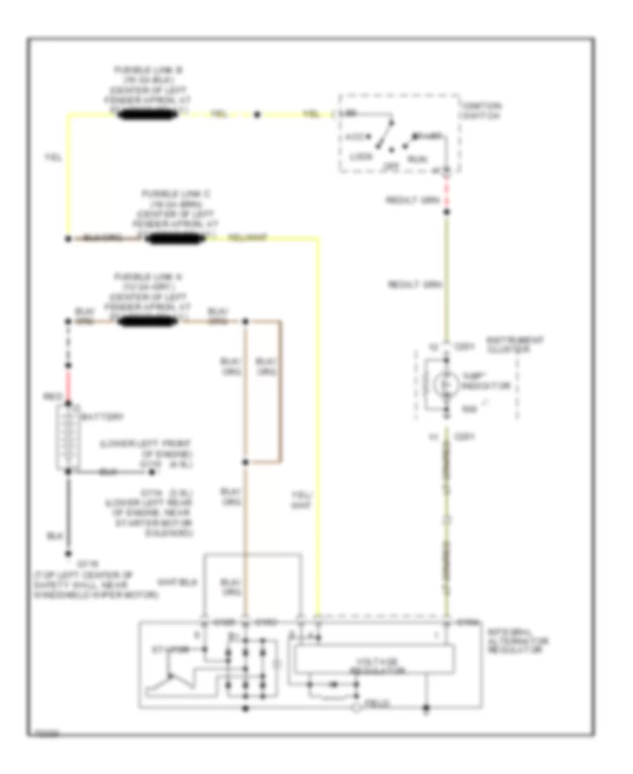
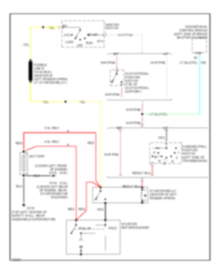
STARTING/CHARGING Charging Wiring Diagram for Ford Aerostar 1995 List of elements for Charging Wiring Diagram for Ford Aerostar 1995: 24 "amp" indicator (3.0l) (lower left rear of engine, near starter motor solenoid) (lower left front of engine) (4.0l) (top left center of safety wall, near windshield wiper motor) Acc Battery C125 C153 C154 C251 Field G110 G114 G116 Ignition switch Instrument cluster Integral alternator regulator Lock Off Red Run Start Stator Voltage regulator Starting Wiring Diagram for Ford Aerostar 1995 List of elements for Starting Wiring Diagram for Ford Aerostar 1995: 28 (3.0l) (lower left rear of engine, near starter motor solenoid) (lower left front of engine) (4.0l) (top left center of safety wall, near windshield wiper motor) 3.0l only 4.0l only A/t Acc Battery Clutch pedal position switch (top of clutch pedal support) G110 G114 G116 Hold Ignition switch Lock M/t Nca Off Park/neutral position switch (left side of transmission) Pnp Powertrain control module (left side of brake master cylinder) Pull-in Red Run Sta Start Starter motor/solenoid Starter relay (center of left fender apron)
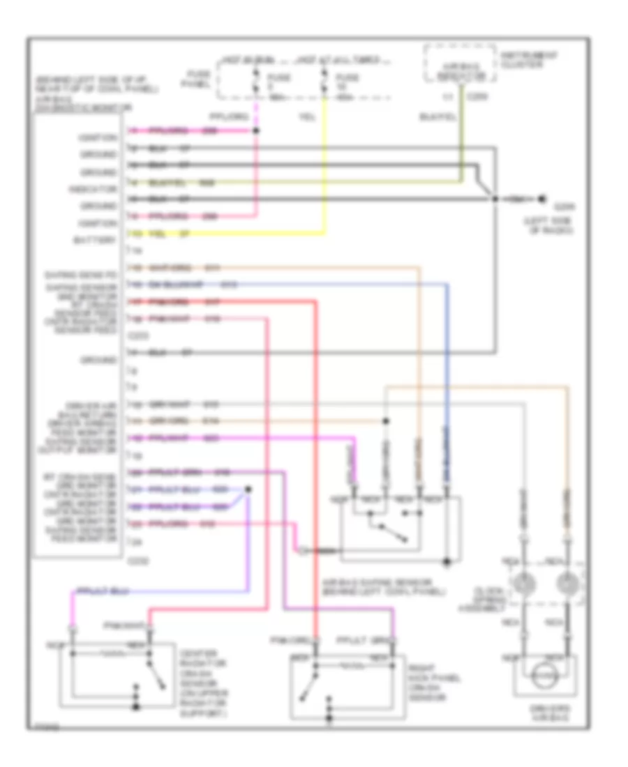
SUPPLEMENTAL RESTRAINTS Supplemental Restraint Wiring Diagram for Ford Aerostar 1995 List of elements for Supplemental Restraint Wiring Diagram for Ford Aerostar 1995: 26 (behind left side of i/p, near top of cowl panel) air bag diagnostic monitor (left side of radio) Air bag indicator Air bag safing sensor (behind left cowl panel) Battery C232 C233 C250 Center radiator crash sensor (on upper radiator support) Clock- spring assembly Driver air bag return driver airbag feed monitor safing sensor output monitor Driver's air bag Fuse 15a Fuse panel G206 Ground Hot at all times Hot in run Ignition Indicator Instrument cluster Nca Right kick panel crash sensor Rt crash sens grd monitor cntr radiator grd monitor cntr radiator grd monitor safing sensor feed monitor Safing sens fd Safing sensor gnd monitor rt crash sensor feed cntr radiator sensor feed
TRANSMISSION
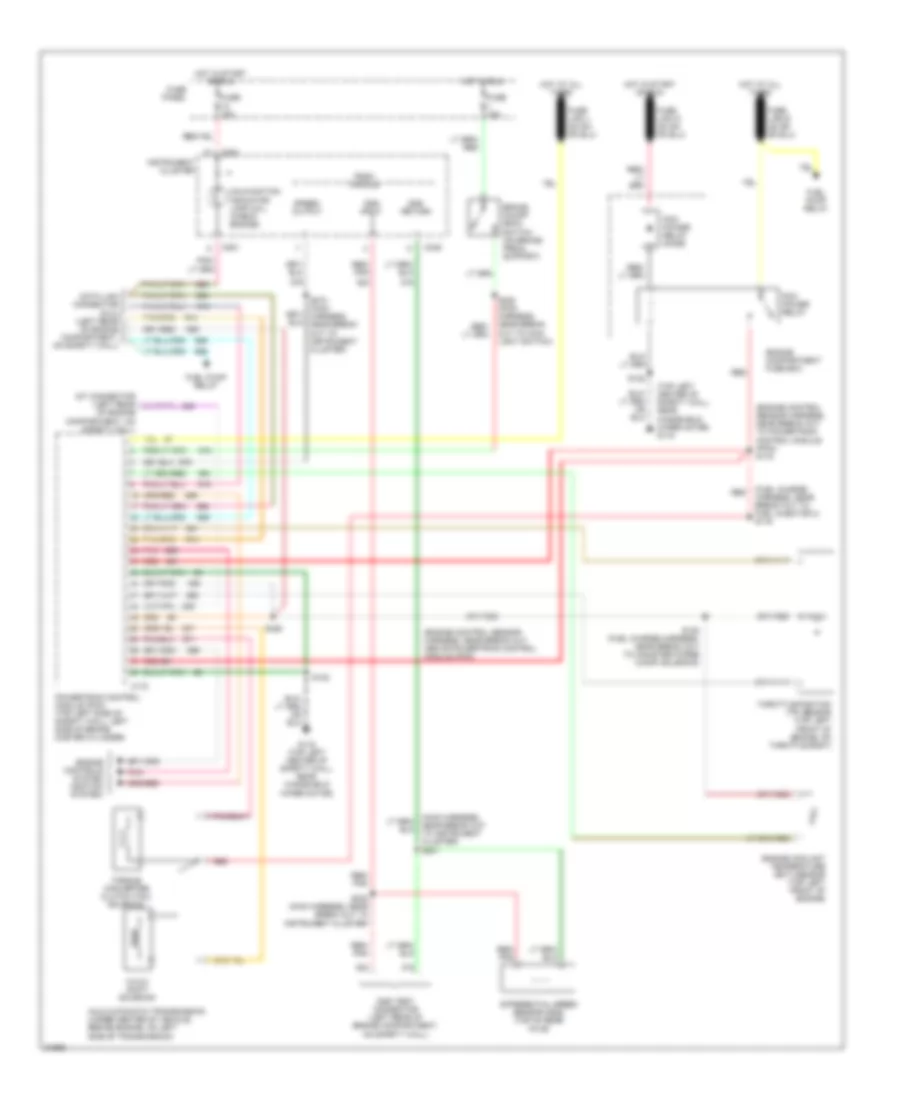
3.0L 3.0L, Transmission Wiring Diagram for Ford Aerostar 1995 List of elements for 3.0L, Transmission Wiring Diagram for Ford Aerostar 1995: 45 (engine control sensor harness, near break out above pcm) (engine control sensor harness, near break out to pcm) s116 (fuel charge harness, near red (top left center of safety wall, near windshield wiper motor) g116 3-4/4-3 shift solenoid A4ld automatic transmission (under center of vehicle, behind engine, on left side of transmission) Brake on/off (boo) switch (on brake pedal support) Break out to fuel injector 2) s119 C172 C249 C251 Data link connector (dlc) (left rear of engine compartment, on safety wall) Differential speed sensor (dss) (top of rear axle) Dss input Dss return Dss test connector (left rear of engine compartment, on safety wall) Engine compartment fuse box Engine controls system (ignition system) Engine coolant temperature (ect) sensor (top center front of engine, above water pump pulley) Fuel pump relay Fuse 15a Fuse panel G116 (top left center of safety wall, near windshield wiper motor) Hot at all times Hot in run Hot in start or run Instrument cluster Malfunction indicator lamp (mil) (check engine) Of engine compartment, on safety wall) Pcm power relay Pcm power relay diode Pnk Powertrain control module (pcm) (top left side of safety wall, left side of brake master cylinder) Psom module Red Red/ pnk S122 S125 S128 (fuel charge harness, near break out to fuel injector 4) S228 (main harness, near break out to main light switch) S232 (main harness, near break out to instrument cluster) S273 (main harness, near break out to instrument cluster) Speed output Throttle position (tp) sensor (top center front of engine, on throttle body) Torque converter clutch (tcc) solenoid
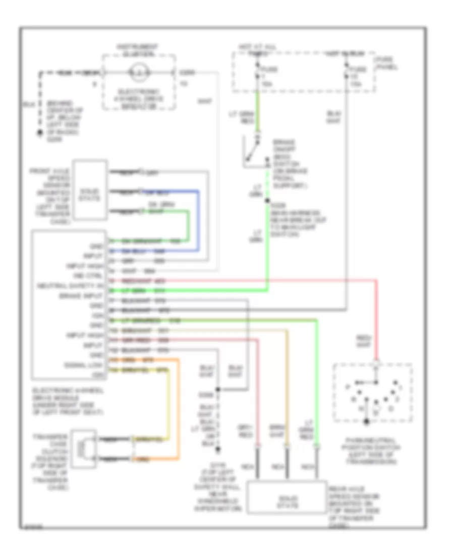
4.0L 4.0L, A4LD Transmission Wiring Diagram for Ford Aerostar 1995 List of elements for 4.0L, A4LD Transmission Wiring Diagram for Ford Aerostar 1995: 44 (engine control sensor harness, near break out above powertrain control module (pcm) (engine control sensor harness, near break out to powertrain control module (pcm)) s116 (fuel charge harness, near break out to fuel injector 3) s119 (top left center of safety wall, near windshield wiper motor) g116 3-4/4-3 shift solenoid A4ld automatic transmission (under center of vehicle, behind engine, on left side of transmission) Brake on/off (boo) switch (on brake pedal support) C172 C249 C251 Data link connector (dlc) (left rear of engine compartment, on safety wall) Differential speed sensor (dss) (top of rear axle) Dss input Dss return Dss test connector (left rear of engine compartment, on safety wall) Engine compartment fuse box Engine controls system (ignition system) Engine coolant temperature (ect) sensor (top left front of engine) Fuel pump relay Fuse 15a Fuse panel G116 (top left center of safety wall, near windshield wiper motor) Hot at all times Hot in run Hot in start or run Instrument cluster Malfunction indicator lamp (mil) (check engine) Of engine compartment, on safety wall) Pcm power relay Pcm power relay diode Pnk Powertrain control module (pcm) (top left side of safety wall, left side of brake master cylinder) Psom module Red Red/ pnk S122 S125 S128 (fuel charge harness, near break out to canister purge (canp) solenoid) S228 (main harness, near break out to main light switch) S232 (main harness, near break out to instrument cluster) S273 (main harness, near break out to instrument cluster) Speed output Throttle position (tp) sensor (top left front of engine, on throttle body) Torque converter clutch (tcc) solenoid 4.0L, Transfer Case Wiring Diagram for Ford Aerostar 1995 List of elements for 4.0L, Transfer Case Wiring Diagram for Ford Aerostar 1995: 27 (behind center of i/p, below left side of radio) g206 Brake input Brake on/off (boo) switch (on brake pedal support) C250 Electronic 4 wheel drive indicator Electronic 4-wheel drive module (under right side of left front seat) Front axle speed sensor (mounted on top left side transfer case) Fuse 15a Fuse panel G116 (top left center of safety wall, near windshield wiper motor) Gnd Hot at all times Hot in run Ign Ind ctrl Input Input high Instrument cluster Nca Neutral safety in Park/neutral position switch (left side of transmission) Rear axle speed sensor (mounted on top right side of transfer case) S228 (main harness, near break out to main light switch) S308 Signal low Solid state Transfer case clutch solenoid (top right side of transfer case)
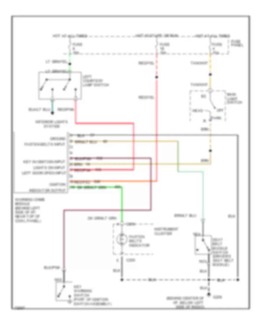
WARNING SYSTEMS Warning System Wiring Diagrams for Ford Aerostar 1995 List of elements for Warning System Wiring Diagrams for Ford Aerostar 1995: 27 (behind center of i/p, below left side of radio) C250 Fasten belts indicator Fasten belts input Fuse 15a Fuse panel G206 Ground Head Hot at all times Hot in start or run Ignition Indicator output Instrument cluster Interior lights system Key in ignition input Key warning switch (part of ignition switch assembly) Left courtesy lamp switch Left door open input Lights on input Main light switch Nca Off Park Red/pnk Seat belt buckle switch (driver's seat belt buckle) Warning chime module (behind left side of i/p, near top of cowl panel)
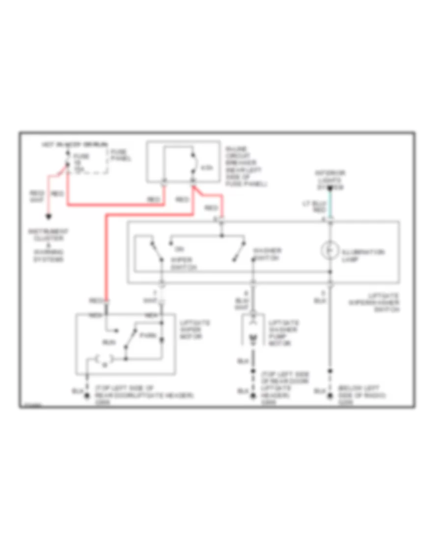
WIPER/WASHER Front Wiper/Washer Wiring Diagram for Ford Aerostar 1995 List of elements for Front Wiper/Washer Wiring Diagram for Ford Aerostar 1995: 35 (front left fender apron, left of battery) 100k ohms 3.3k ohms 4.07k 7.25k Circuit breaker 6a Fuse panel G100 Gnd Ground Hot in accy or run Ignition Input Int max Int min Multi- function switch Off Off 36.27k ohms Ohms Park Park switch Pump motor control Red Run Washer switch Windshield washer pump motor (in washer reservoir) Windshield wiper motor Wiper control module (right of steering column) Wiper mode Wiper motor Wiper motor (common) Wiper motor (hi) Wiper motor (lo) Wiper motor park sw Wiper switch Rear Wiper/Washer Wiring Diagram for Ford Aerostar 1995 List of elements for Rear Wiper/Washer Wiring Diagram for Ford Aerostar 1995: 20 (below left side of radio) g206 (top left side of rear door/ liftgate header) g906 (top left side of rear door/liftgate header) g906 4.5a Fuse 15a Fuse panel Hot in accy or run Illumination lamp In-line circuit breaker (near left side of fuse panel) Instrument cluster & warning systems Interior lights system Liftgate washer pump motor Liftgate wiper motor Liftgate wiper/washer switch Nca Park Red Run Washer switch Wiper switch