Разделы схем — 26 (всего 70)
AIR CONDITIONING ANTI-LOCK BRAKES ANTI-THEFT BODY COMPUTER COMPUTER DATA LINES CRUISE CONTROL ELECTRONIC SUSPENSION ENGINE PERFORMANCE EXTERIOR LIGHTS GROUND DISTRIBUTION HEADLIGHTS HORN INSTRUMENT CLUSTER INTERIOR LIGHTS POWER DISTRIBUTION POWER DOOR LOCKS POWER MIRRORS POWER SEATS POWER WINDOWS RADIO SHIFT INTERLOCKS STARTING/CHARGING SUPPLEMENTAL RESTRAINTS TRANSMISSION WARNING SYSTEMS WIPER/WASHER
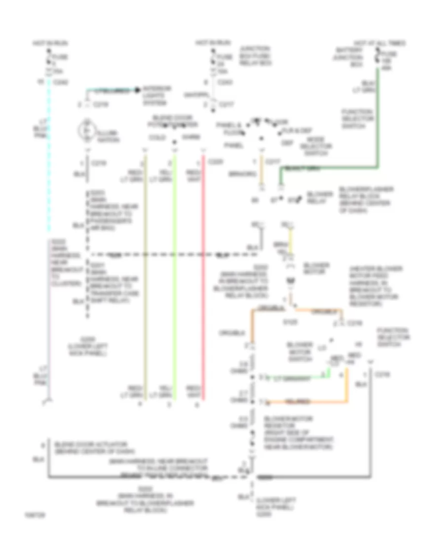
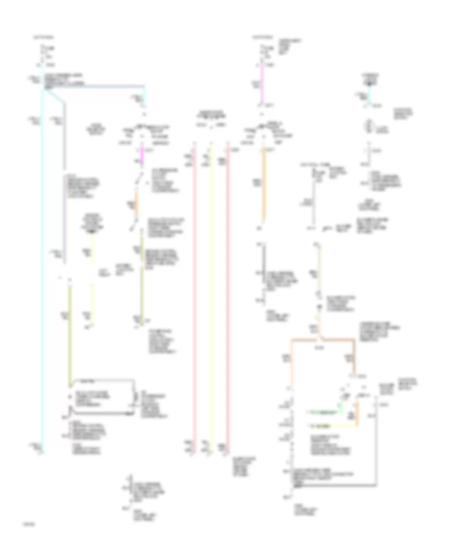
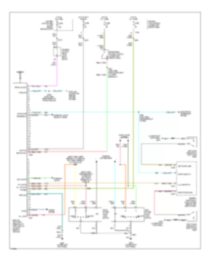
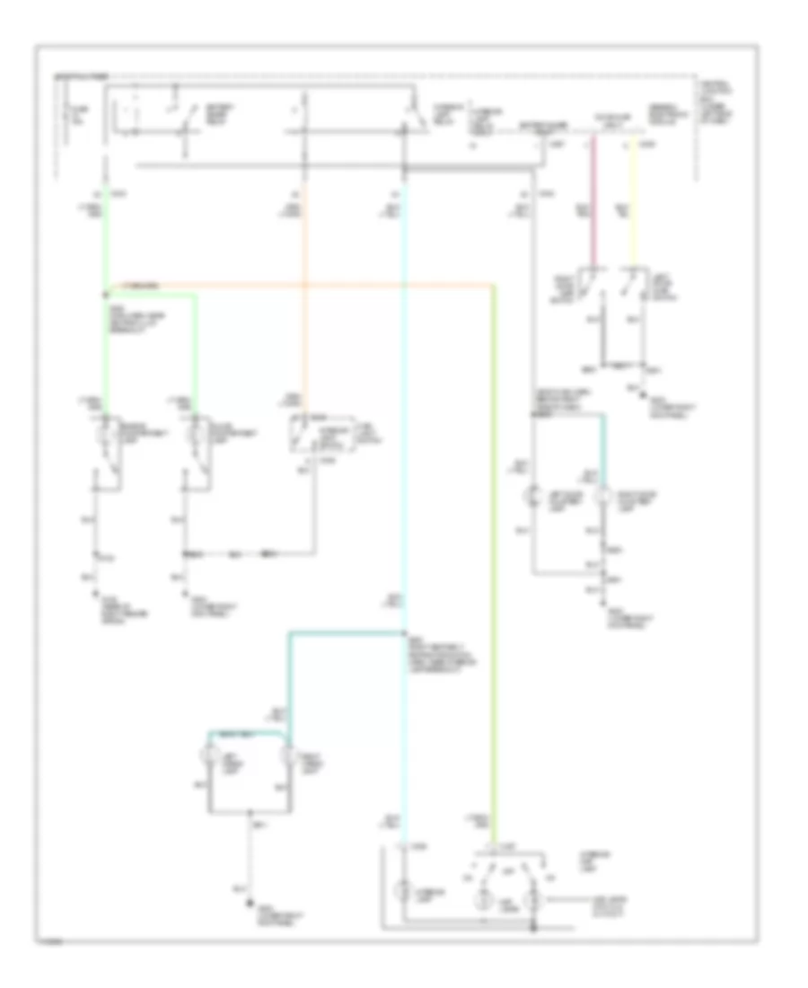
AIR CONDITIONING Heater Wiring Diagram for Ford Pickup F350 Super Duty 1999 List of elements for Heater Wiring Diagram for Ford Pickup F350 Super Duty 1999: 48 (heater blower motor feed harness, in breakout to blower motor resistor) (lower left kick panel) g200 (main harness, near breakout to in-line connector behind right side of dash) 0.6 ohms 2.7 ohms 3.8 ohms 87a Battery junction box Blend door actuator (behind center of dash) Blend door potentiometer Blower motor Blower motor resistor (right side of engine compartment, near blower motor) Blower motor switch Blower relay Blower/flasher relay block (behind center of dash) C217 C218 C219 C220 C242 C243 Cold Def Floor Flr & def Function selector switch Fuse 10a Fuse 15a Fuse 40a G200 (lower left kick panel) Hot at all times Hot in run Illumi- nation Interior lights system Junction box fuse/ relay box Med hi Med lo Mode selector switch Off Panel Panel & S125 S200 S201 (main harness, near breakout to transfer case shift relay) S202 (main harness, in breakout to blower/flasher relay block) S203 (main harness, near breakout to passenger's air bag) S222 (main harness, near breakout to cluster) Warm Manual A/C Wiring Diagram for Ford Pickup F350 Super Duty 1999 List of elements for Manual A/C Wiring Diagram for Ford Pickup F350 Super Duty 1999: 59 (engine control sensor harness, near breakout to mega fuse (pdb)) s126 (heater blower motor feed harness, in breakout to blower motor resistor) (main harness, in breakout to blower/flasher relay block) s202 (main harness, near breakout to in-line connector behind right side of dash) s200 (main harness, near breakout to instrument cluster) s222 0.6 ohms 2.7 ohms 3.8 ohms 87a A/c A/c clutch cycling pressure switch (right rear corner of engine compartment) A/c clutch diode (taped in harness, near a/c compressor) A/c compressor clutch solenoid (left side of engine compartment) A/c pressure cut off switch (right side of engine compartment) Battery junction box Blend door actuator (behind center of dash) Blend door potentiometer Blower motor (right side of engine compartment) Blower motor resistor (right side of engine compartment, near blower motor) Blower motor switch Blower relay Blower/flasher relay block (behind center of dash) C217 C218 C219 C220 C242 C243 Cold Def Defrost Engine controls system (pcm power relay) Floor Flr & def Flr/def Function selector switch Fuse 10a Fuse 15a Fuse 40a G102 (rear of right fender apron) G200 (lower left kick panel) Hot at all times Hot in run Illumi- nation Instrument panel fuse box Interior lights system Max a/c Med hi Med lo Mode selector switch Off panel/floor Panel Panel & off floor Powertrain control module (pcm) (right side of engine compartment) S112 (engine control sensor harness, near breakout to battery junction box) S125 S203 (main harness, near breakout to passenger's air bag) Warm Wot relay
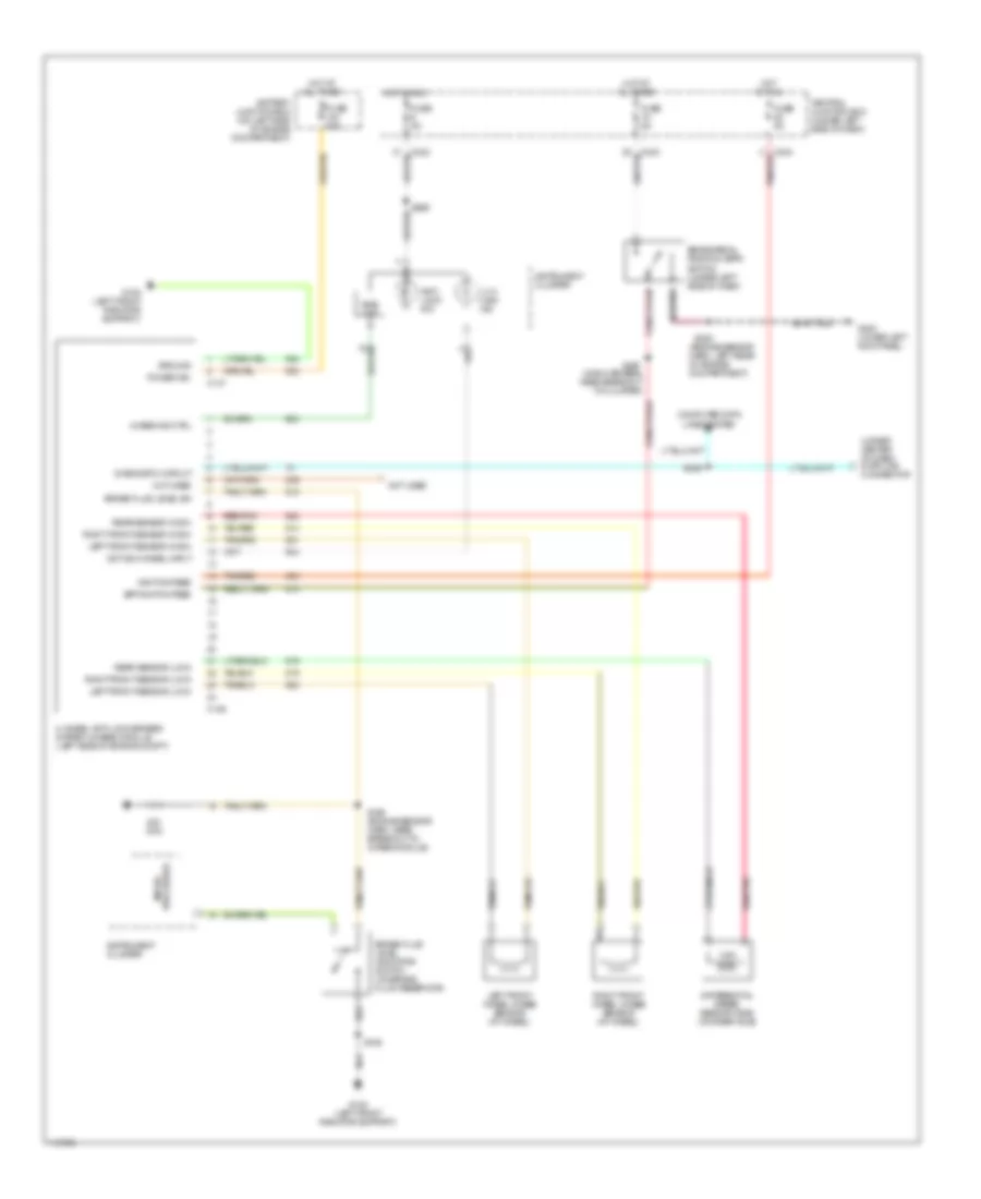
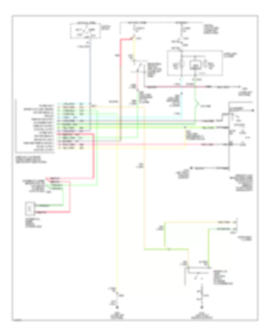
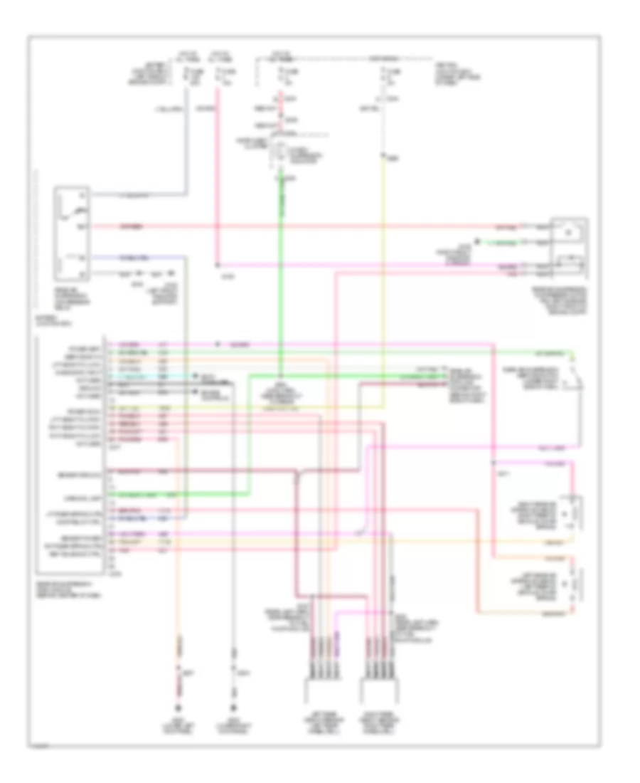
ANTI-LOCK BRAKES All-Wheel ABS Wiring Diagram for Ford Pickup F350 Super Duty 1999 List of elements for All-Wheel ABS Wiring Diagram for Ford Pickup F350 Super Duty 1999: 51 (engine sensor harn, left rear of engine compartment) (main harness, near breakout to cluster) (under center of dash) data link connector 4 x 4 high ind 4-wheel anti-lock brakes system (4wabs) module (left side of engine compt) 4wabs ind ctrl Active 4-wheel input Anti- lock ind Battery junction box (on left side of engine compartment) Bias ckt Bpp switch feed Brake fluid level indicator switch (on brake fluid reservoir) Brake fluid level sw Brake pedal position (bpp) switch (under left side of dash) C146 C147 C242 C243 Central junction box (under left side of dash) Computer data lines system Diagnostic circuit Differential speed sensor (dss) (on rear axle) Fuse 50a Fuse 5a G108 (left front radiator support) G200 (lower left kick panel) Ground Hot at all times Hot in run Ignition feed Instrument cluster Left front sensor (high) Left front sensor (low) Left front wheel 4wabs sensor (at wheel) Not used Ohm Power (b+) Processor micro- Rear sensor (high) Rear sensor (low) Red/pnk Right front sensor (high) Right front sensor (low) Right front wheel 4wabs sensor (at wheel) S106 S156 (engine sensor harn, near breakout to 4wabs module) S208 S229 S265 S297 Tan/red Rear Wheel ABS Wiring Diagram for Ford Pickup F350 Super Duty 1999 List of elements for Rear Wheel ABS Wiring Diagram for Ford Pickup F350 Super Duty 1999: 57 (lower left kick panel) 1.2 ohms 22k ohms 4 x 4 high ind 4.0 ohms Acc Anti- lock ind Bias circuit Bpp switch input Brake fluid level indicator switch (on brake fluid reservoir) Brake fluid level sensor Brake pedal position (bpp) switch (under left side of dash) C236 C242 C243 Central junction box (under left side of dash) Diff spd sens (hi) Diff spd sens (lo) Differential speed sensor (on rear axle) Differential speed sensor data link connector (in central junction box) c268 Dump sol Dump sol output Fuse 15 5a Fuse 6 5a G108 (left front radiator support) G200 G200 (lower left kick panel) Ground Hot at all times Hot in run Ignition switch Instrument cluster Iso sol nca Iso sol output Lock Nca Not used Off Power input Rabs active output Rabs ind control Rabs test/keep alive input Rear anti-lock brake system (rabs) module (behind right side of dash) Rear anti-lock brake system (rabs) proportioning valve switch assembly (in left side of engine compt) Red Red/pnk Run S106 S208 S217 S232 (main harn. near break- out to cluster) S265 S291 (main harn, near breakout to rabs module) S297 (main harn, near break- out to cluster) Start Valve reset input Valve reset switch
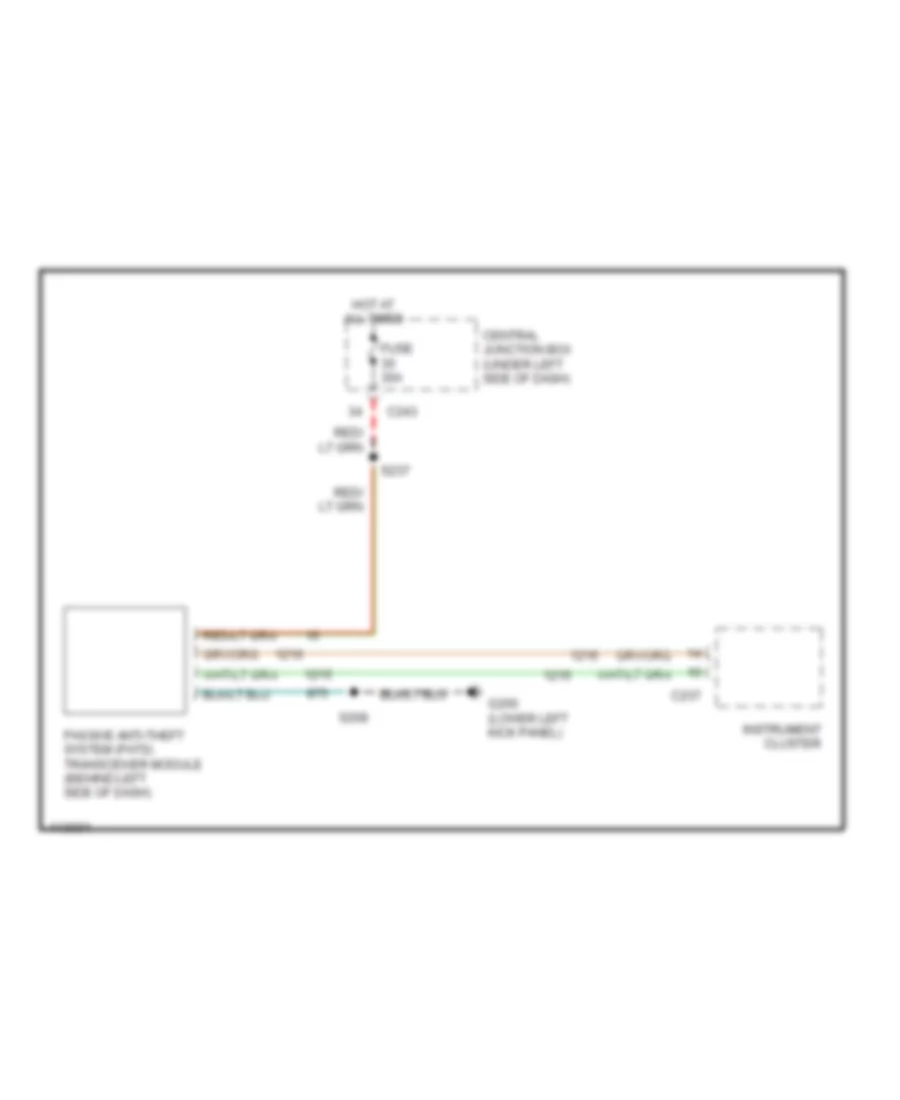
ANTI-THEFT Forced Entry Wiring Diagram for Ford Pickup F350 Super Duty 1999 List of elements for Forced Entry Wiring Diagram for Ford Pickup F350 Super Duty 1999: 64 (body harn, near breakout to remote anti-theft person- ality module) s234 (body harn, near breakout to remote anti-theft personality module) (lower right kick panel) g203 All lock All unlock Antenna Battery junction box (in left side of engine compt) Bpp switch Brake pedal position switch (under left side of dash) C239 C240 C242 C256 C257 Central junction box (under left side of dash) Data link connector (behind center of dash) Datalink Door ajar Door ajar out Door locks system Driver's unlock relay (lock relay block) Drvr unlock Electronic suspension system Ext lights Exterior lights Exterior lights (backup lamps) Fuse 15a Fuse 5a G200 (lower left kick panel) G203 (lower right kick panel) Generic electronic module (gem) (behind left side of dash) Ground Horn Horns system Hot at all times Hot in accy or run Ignition Illum entry in Int lights Interior lights system Left door ajar Left door ajar switch (left door jamb) Left power door lock switch Lock Nca Power Remote anti-theft personality (rap) module (in right rear of vehicle) Reverse in Right door ajar Right door ajar switch (right door jamb) Right power door lock switch S203 S204 S208 S216 S220 S223 S229 (main harn, near breakout to evo module) S235 S268 (main harn, near breakout to gem) S297 (main harn, near instrument cluster breakout) S500 S600 Unlock Passive Anti-theft Wiring Diagram for Ford Pickup F350 Super Duty 1999 List of elements for Passive Anti-theft Wiring Diagram for Ford Pickup F350 Super Duty 1999: 10 C237 C243 Central junction box (under left side of dash) Fuse 30a G200 (lower left kick panel) Hot at all times Instrument cluster Passive anti-theft system (pats) transceiver module (behind left side of dash) S208 S237
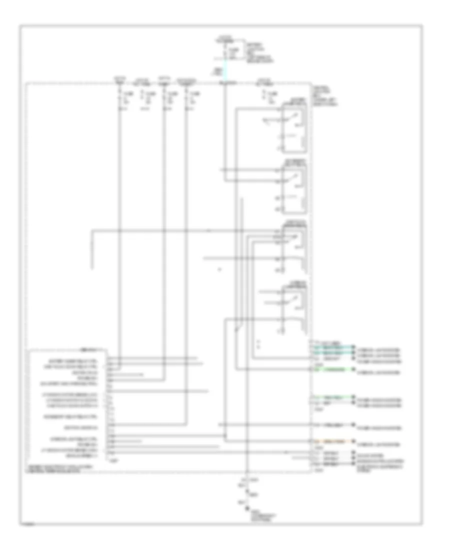
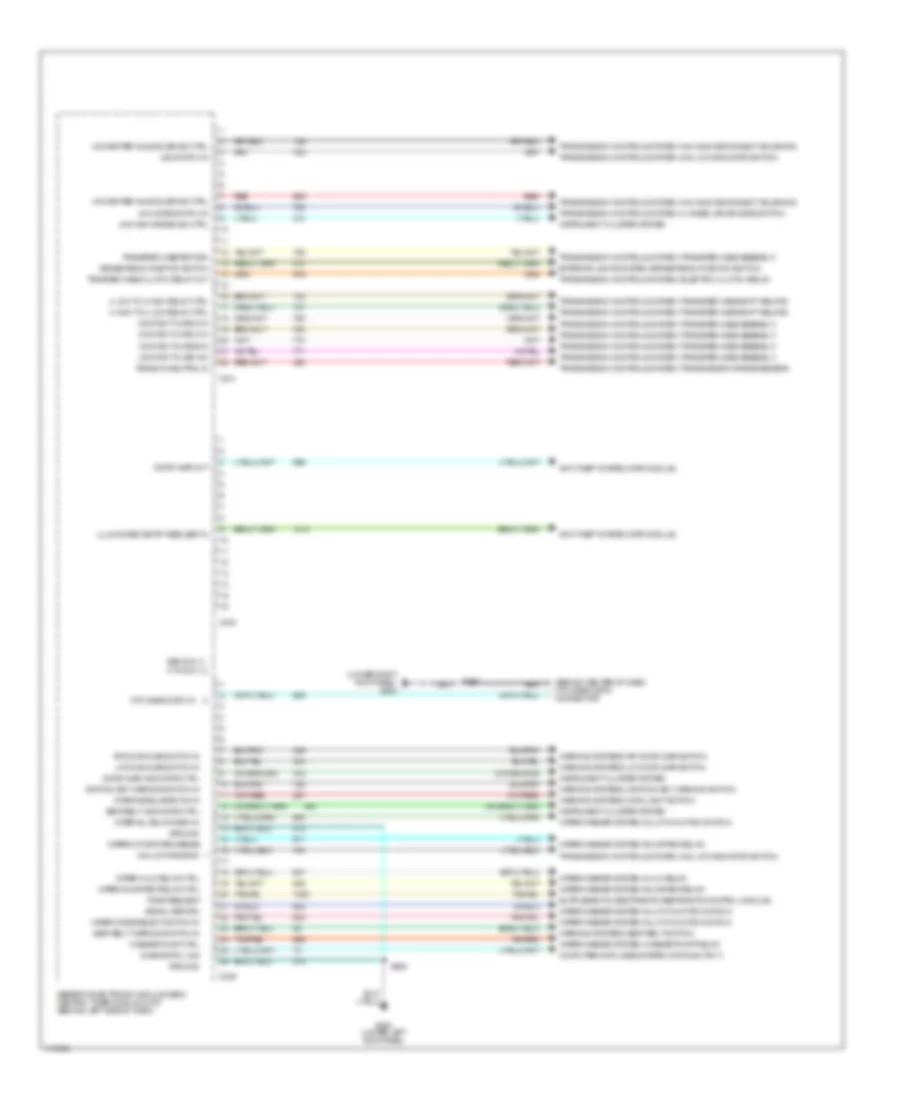
BODY COMPUTER Body Computer Wiring Diagrams (1 of 2) for Ford Pickup F350 Super Duty 1999 List of elements for Body Computer Wiring Diagrams (1 of 2) for Ford Pickup F350 Super Duty 1999: 41 (not used) 87a Accessory delay relay Accessory delay relay ctrl Battery junction box (left side of engine compt) Battery saver relay Battery saver relay ctrl C242 C243 C267 Central junction box (under left side of dash) Electronic suspension system Engine controls system Fuse 15a Fuse 30a Fuse 5a G203 (lower right kick panel) Gem only Generic electronic module (gem)/ central timer module (ctm) Hot at all times Hot in Hot in run Hot in run or acc Ign (start) gnd (park/neutral) Ignition (acc/run) Ignition (run) Interior lamp relay Interior lamp relay ctrl Interior lights system Lf window motor sense (high) Lf window motor sense (low) Lf window switch in (down) One touch down relay One touch down relay ctrl One touch down switch in Power (b+) Power windows system S205 Sound system Start Vehicle speed (+) Body Computer Wiring Diagrams (2 of 2) for Ford Pickup F350 Super Duty 1999 List of elements for Body Computer Wiring Diagrams (2 of 2) for Ford Pickup F350 Super Duty 1999: 69 (behind center of dash) ctm diagnostic connector (lower right kick panel) g203 (park/headlamps on) in 4 high to 4 low relay ctrl 4 low to 4 high relay ctrl 4x2 center axle solenoid ctrl 4x4 center axle solenoid ctrl 4x4 high range ind ctrl 4x4 low range in 4x4 mode switch in 4x4 switch in Anti-theft system (rap module) Brake pedal position switch C239 C240 C241 Computer data lines system (datalink pin 7) Contact plate a in Contact plate b in Contact plate c in Contact plate d in Ctm diagnostic in Diagnostic link Door ajar indicator ctrl Door ajar out Exterior lights system (brake pedal position switch) G200 (lower left kick panel) Gem only ctm only Generic electronic module (gem)/ central timer module (ctm) (behind left side of dash) Ground Ignition key warning switch in Illuminated entry request in Instrument cluster system Interval delay/wash in Lf door ajar switch in Red Rf door ajar switch in S203 S208 Seat belt indicator ctrl Seat belt warning switch in Signal return Tan/red Tone request Trans in neutral in Transfer case return Transmission controls system (4 wheel drive mode switch) Transmission controls system (4x2 axle disconnect solenoid) Transmission controls system (4x4 axle disconnect solenoid) Transmission controls system (4x4 low indicator switch) Transmission controls system (electric clutch relay) Transmission controls system (transfer case assembly) Transmission controls system (transfer case shift relays) Transmission controls system (transmission range sensor) Trnsfer case clutch relay out Warning systems (ignition key warning switch) Warning systems (lf door ajar switch) Warning systems (main light switch) Warning systems (rf door ajar switch) Warning systems (seat belt switch) Washer pump ctrl Wiper hi/lo relay ctrl Wiper mode select switch in Wiper motor park sense Wiper run/park relay ctrl Wiper/washer system (hi/lo relay) Wiper/washer system (multi-function switch) Wiper/washer system (run/park relay) Wiper/washer system (washer pump relay)
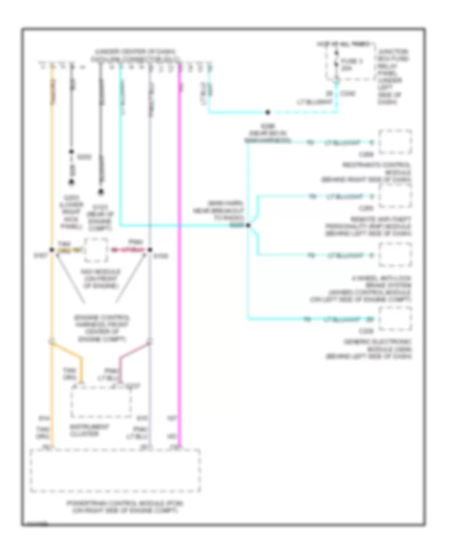
COMPUTER DATA LINES Computer Data Lines for Ford Pickup F350 Super Duty 1999 List of elements for Computer Data Lines for Ford Pickup F350 Super Duty 1999: 23 (engine control harness, front center of engine compt) (main harn, near breakout to radio) s229 (under center of dash) data link connector (dlc) 4 wheel anti-lock brake system (4wabs) control module (on left side of engine compt) C208 C237 C239 C242 C256 Fuse 3 20a G123 (rear of engine compt) G203 (lower right kick panel) Generic electronic module (gem) (behind left side of dash) Hot at all times Instrument cluster Junction box fuse/ relay panel (under left side of dash) Ngv module (on front of engine) Powertrain control module (pcm) (on right side of engine compt) Remote anti-theft personality (rap) module (behind left side of dash) Restraints control module (behind right side of dash) S156 S157 S289 (near b/o in main harness)
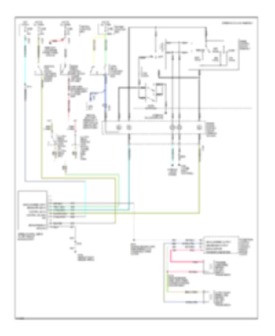
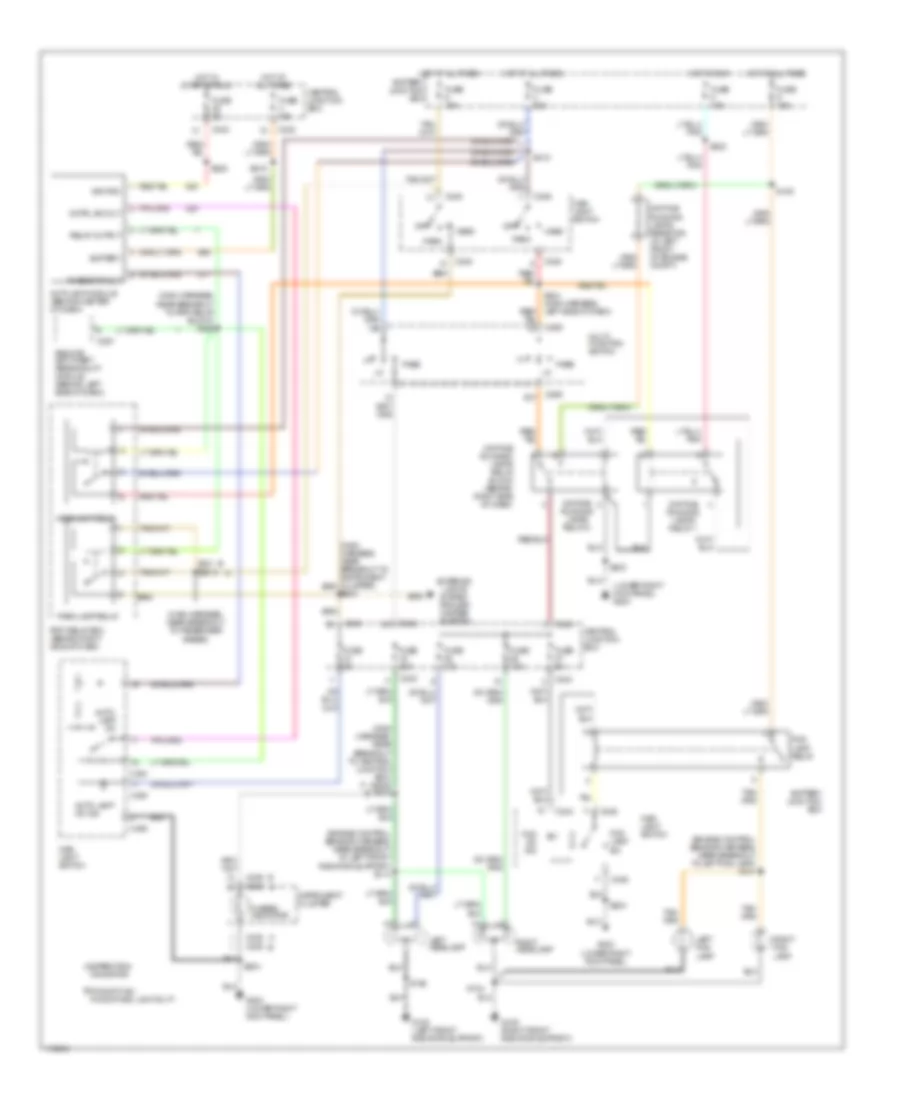
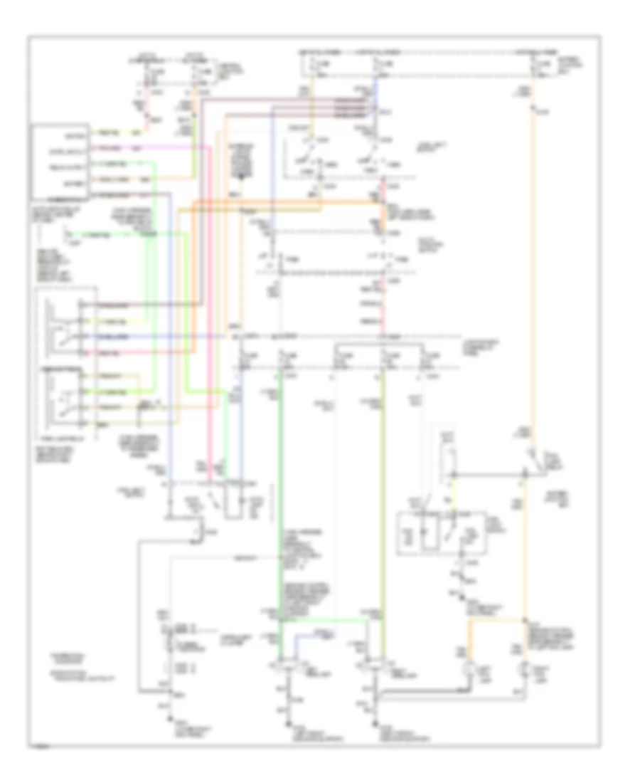
CRUISE CONTROL Cruise Control Wiring Diagram for Ford Pickup F350 Super Duty 1999 List of elements for Cruise Control Wiring Diagram for Ford Pickup F350 Super Duty 1999: 57 (main harn, near breakout to instrument cluster) s297 A/t Accel Air bag sliding contact (top of steering column) Battery junction box Brake pedal position (bpp) switch (under left side of dash) Brake press in C234 C242 C243 C257 Central junction box Clutch pedal position (ccp) switch (on clutch pedal arm) Clutch pedal position (ccp) switch jumper (left side of dash) Coast Control sw gnd Control sw in Deactiva- tion switch (left rear corner of engine compt) Fuse 15a Fuse 20a Fuse 5a G105 (rear of right fender apron) G203 (lower right kick panel) Ground Horn relay (in battery junction box) Horn switches Hot at all times Hot in run Hrn rly Ign Interior lights system M/t Nca Off Ohms Oss sensor output Output shaft speed (oss) sensor (on left side of transmission) Pnk Powertrain control module (on right side of engine compt) Rear anti- lock brake system (rabs) module Red Remote anti-theft personality (rap) module (behind left side of dash) Resume S102 S112 S138 (engine sensor harn, right rear corner of engine compartment) S143 (engine sensor harn, near breakout to windshield wiper motor) Set/ Signal return Speed control servo (in left side of engine compt) Speed control switch assembly Steering column assembly Steering column ground Transfer case sp sen Transfer case speed sensor (at left rear of transmission) Vehicle speed input Vehicle speed output
ELECTRONIC SUSPENSION Electronic Suspension Wiring Diagram for Ford Pickup F350 Super Duty 1999 List of elements for Electronic Suspension Wiring Diagram for Ford Pickup F350 Super Duty 1999: 60 rear air suspension service switch (under right side of dash) 87a Battery junction box Battery junction box (left side of engine compt) Body computer C236 C242 C276 C277 Central junction box (under left side of dash) Check suspension indicator Comp relay ctrl Connector (behind right side of dash) Diagnostic input Engine controls Fuse 15a Fuse 50a Fuse 5a G108 (left front radiator support) G109 (right front radiator support) G200 (lower left kick panel) G203 (lower right kick panel) Ground Hot at all times Hot in run Instrument cluster Left rear air spring solenoid (left rear of vehicle, on air spring) Left rear height sensor (left rear wheelwell) Lft height in (high) Lft height in (low) Lft rear spring ctrl Nca Not used Pnk Power (bat) Power (run) Rear air suspension (ras) module (behind center of dash) Rear air suspension compressor motor and vent soenoid (right front of engine compt) Rear air suspension compressor relay Rear air suspension data link Rht height in (high) Rht height in (low) Rht rear spring ctrl Right rear air spring solenoid (right rear of vehicle, on air spring) Right rear height sensor (right rear wheelwell) S105 S152 S203 S207 S236 S265 S294 (main harn, near breakout to airbag diag monitor) S409 (rear lamp harn, near breakout to fuel pump module) S410 (rear lamp harn, near breakout to fuel pump module) S411 Sensor ground Sensor power Service sw in Vent solenoid ctrl Warning lamp
ENGINE PERFORMANCE
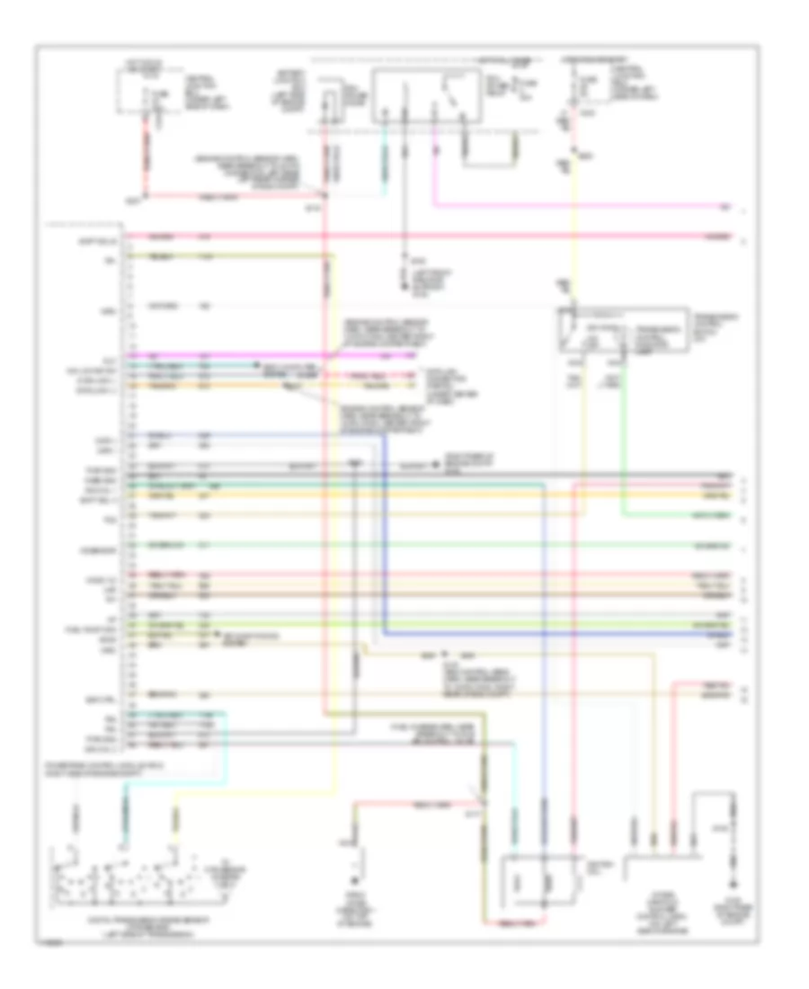
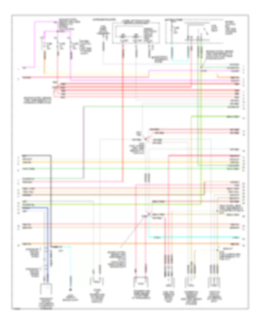
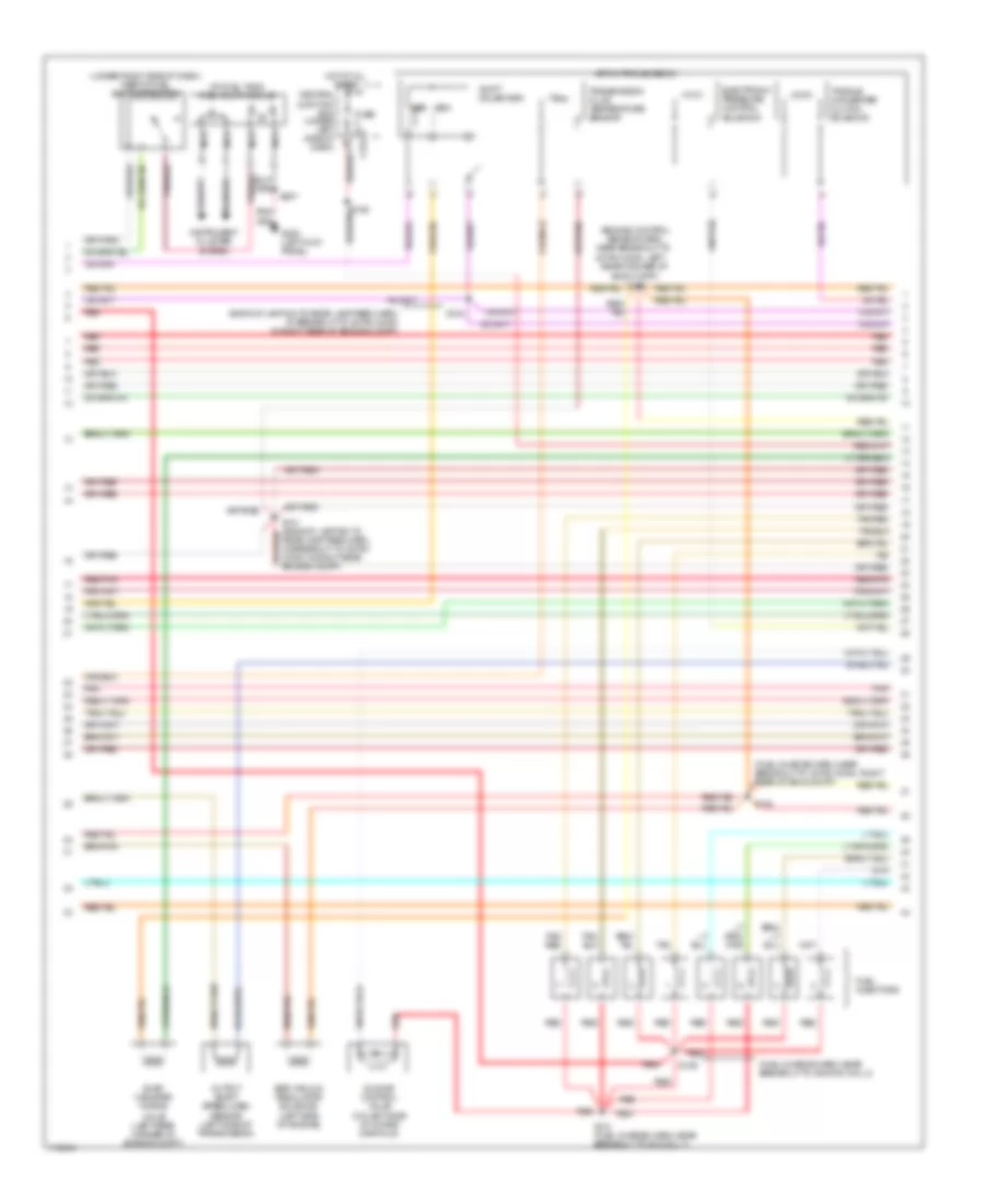
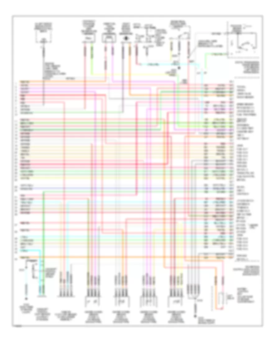
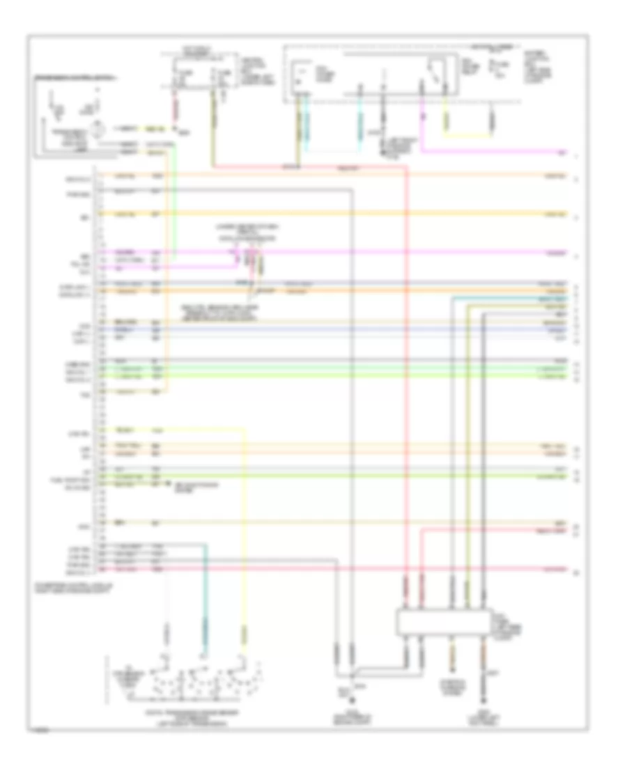
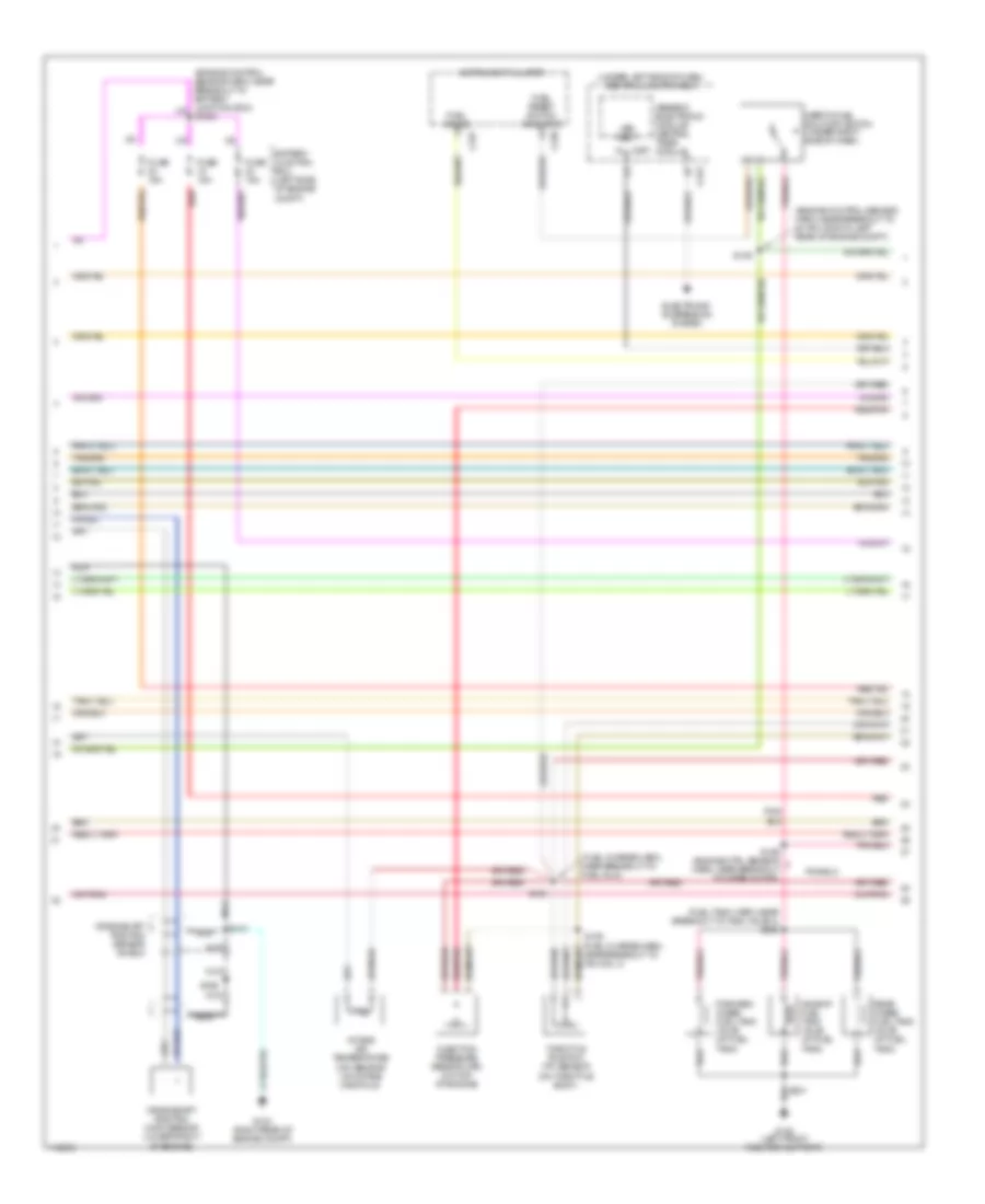
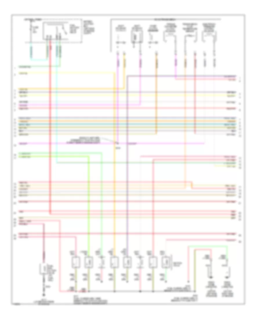
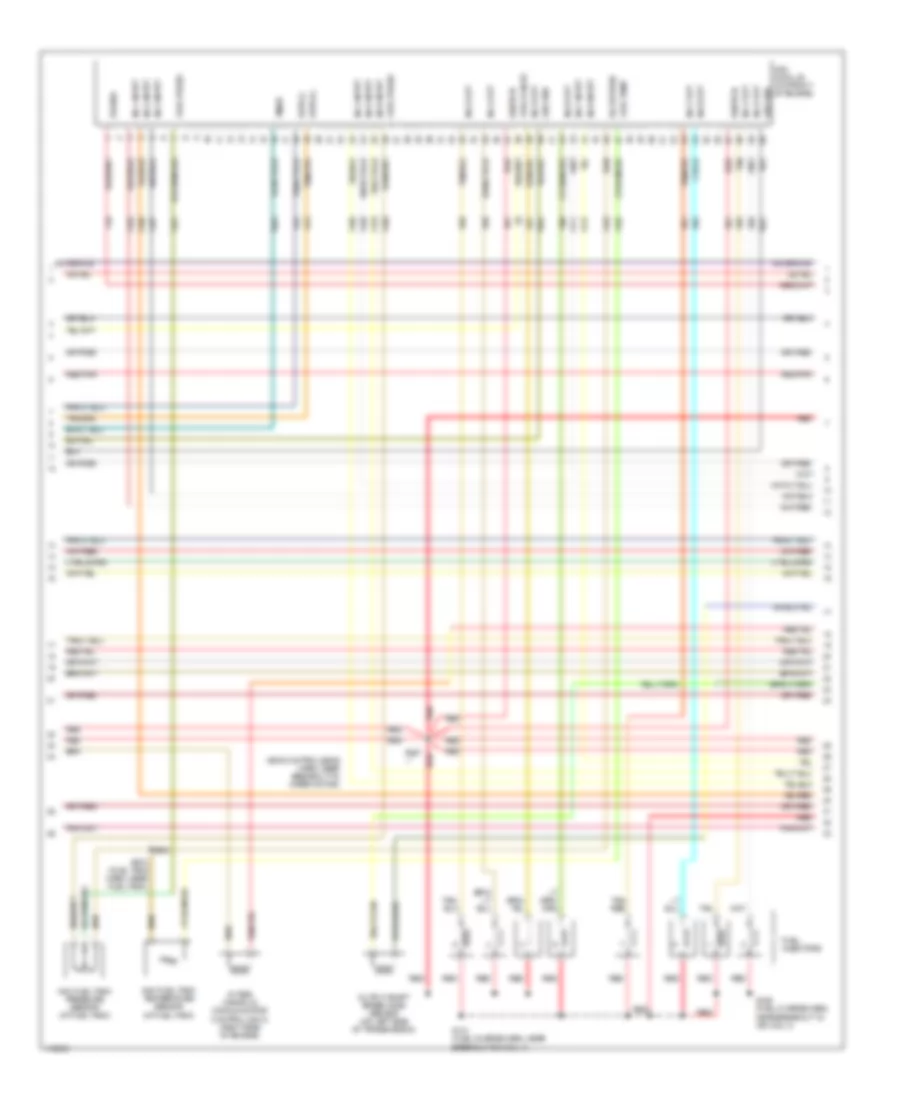
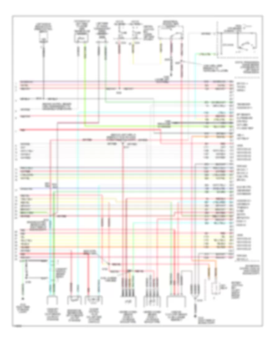
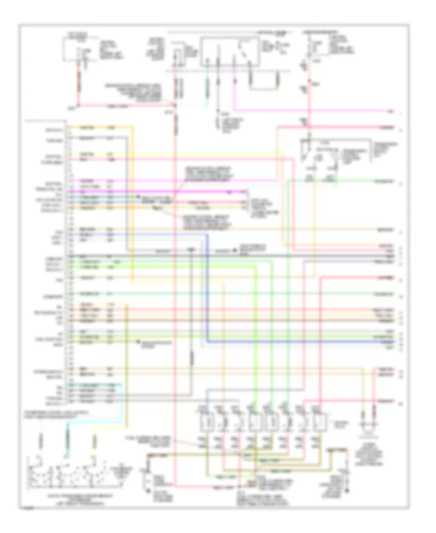
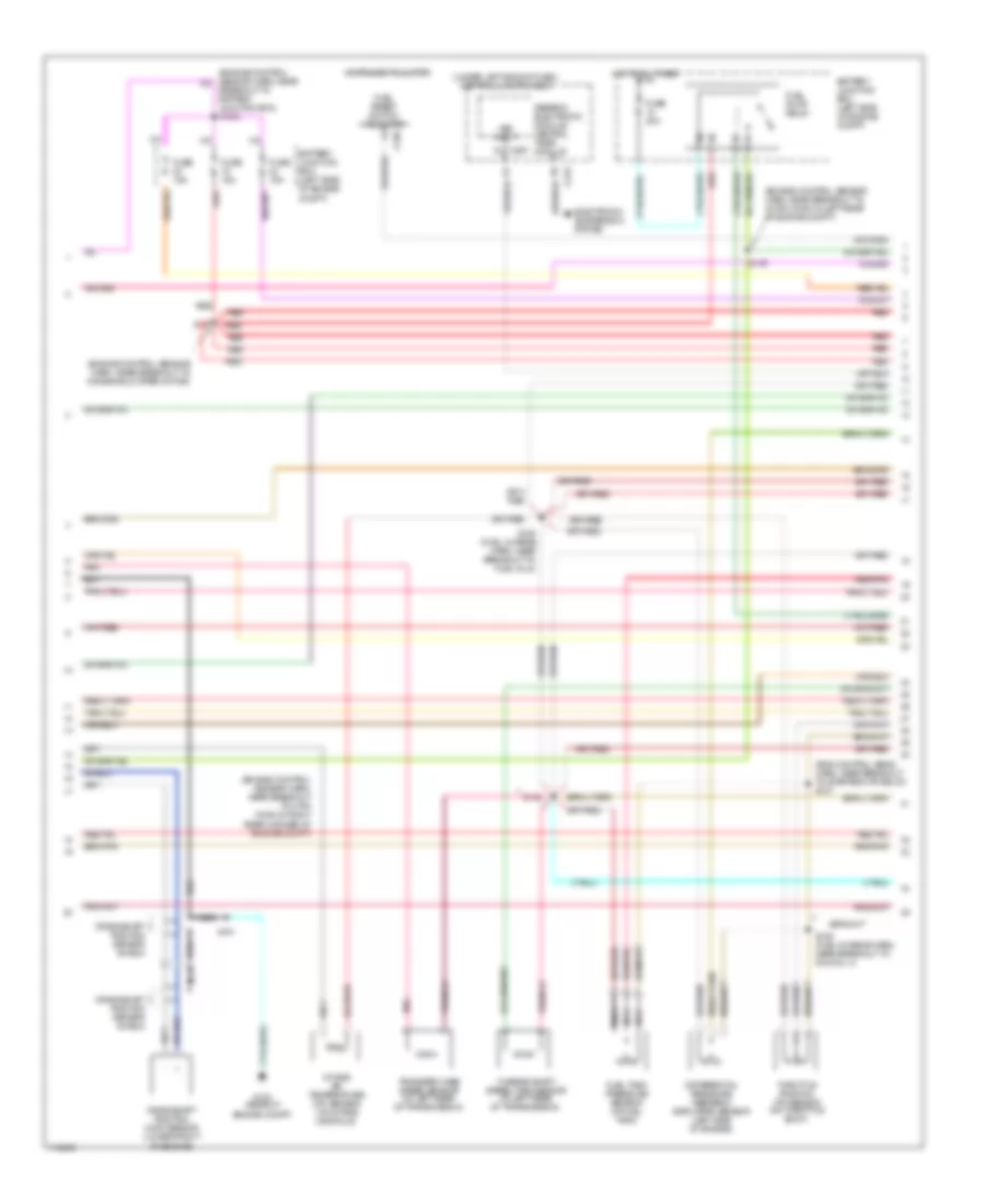
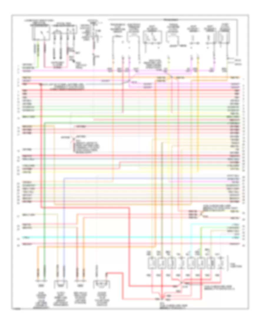
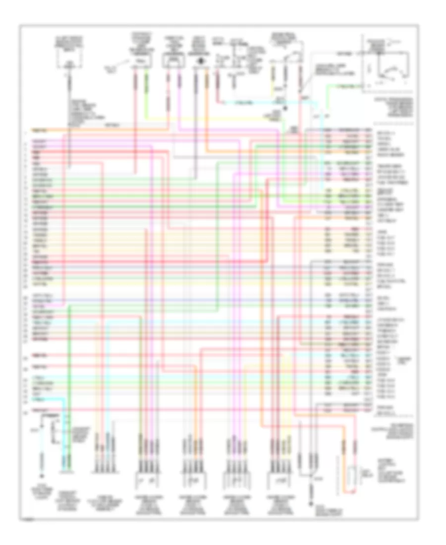
4.2L 4.2L, Engine Performance Wiring Diagrams (1 of 4) for Ford Pickup F350 Super Duty 1999 List of elements for 4.2L, Engine Performance Wiring Diagrams (1 of 4) for Ford Pickup F350 Super Duty 1999: 65 (engine control sensor harn, near breakout to 12-pin conn, center front of engine compartment) (engine control sensor harn, near breakout to 40-pin connector, left rear left rear corner of eng compt) (fuel charge harn, near breakout to idle air control valve) (left front radiator support) g108 (right rear of engine compt) g123 4x4 low ind sw 820 ohms Accs Air conditioning system Battery junction box (left side of engine compt) Body computer system C243 Case gnd Central junction box (under left side of dash) Ckp(+) Ckp(-) Data link (+) Data link (-) Data link connector (partial) (under center of dash) Digital transmission range sensor (dtr sensor) (left side of transmission) Dlc Evr ctrl Fuel pump mon Fuse 30a Fuse 5a G105 (right rear of engine compt) Ho2s (12) Hot at all times Hot in run or start Iat Ign coil 1 Ign coil 2 Ignition coil Imrc Intake manifold runner control (imrc) (on left side of engine) Ks sensor Maf Nca O/d off Pcm power diode Pcm power relay Powertrain control module (pcm) (right side of engine compt) Pwr gnd R n Radio noise capacitor 1 (on top of engine) S100 S106 S116 S117 S130 (eng control sens harn, near breakout to 16-pin conn, right rear of eng compt) S153 S156 S157 S225 S237 Shift sol a Shift sol b Tcs Tft To dtr sensor (diagram 4 of 4) Tr1 Tr2 Tr4 Transmission control indicator lamp Transmission control switch (a/t) 4.2L, Engine Performance Wiring Diagrams (2 of 4) for Ford Pickup F350 Super Duty 1999 List of elements for 4.2L, Engine Performance Wiring Diagrams (2 of 4) for Ford Pickup F350 Super Duty 1999: 36 (eng control sens harn, near breakout to starter mtr relay) s137 (engine control sensor harn, near breakout to 4-pin conn in right rear corner of engine compt) (engine control sensor harn, near breakout to 40-pin conn in left rear of engine compt) (engine control sensor harn, near breakout to windshield wiper motor) (under left side of dash) central junction box Battery junction box (left side of engine compt) Breakout to battery junction box) s1003 C236 C267 Crankshaft position (ckp) sensor (lower front of engine) Crankshaft position sensor shield Differential pressure feedback egr (dpfe) sensor (right side of engine) Electronic suspension system Fuel pump relay Fuel reset switch indicator Fuel tank pressure sensor (at fuel tank) Fuse 15a Fuse 20a G123 (rear of engine compt) Generic electronic module/ central timer module Hot at all times Instrument cluster Intake air temperature (iat) sensor (on intake manifold) Nca Pnk Red Red/pnk S101 S127 S135 (fuel charge harn, near breakout to fuel inj 4) S136 (fuel charge harn, near breakout to fuel inj 2) S138 S139 Throttle position (tp) sensor (on throttle body) Transfer case speed sensor (at left rear of transmission) Vss input 4.2L, Engine Performance Wiring Diagrams (3 of 4) for Ford Pickup F350 Super Duty 1999 List of elements for 4.2L, Engine Performance Wiring Diagrams (3 of 4) for Ford Pickup F350 Super Duty 1999: 39 (at fuel tank) fuel pump module (backup lamp sw to rear lamp feed harn, at breakout to 38-pin conn in right rear of engine compt) (engine control (fuel charge harn, near breakout to 16-pin conn, right rear of eng compt) (fuel charge harn, near top of cylinder 2) (under right side of dash) inertia fuel shut-off switch 4r70w transmission Central junction box (under left side of dash) Egr vacuum regulator solenoid (right side of engine) Electronic pressure control solenoid Eng compt) Evap canister purge Fuel injectors Fuse 5a G200 (left kick panel) Hot at all times Idle air control valve (on left side of intake manifold) Instrument cluster system Nca Near breakout to 40-pin conn, left Output shaft speed (oss) sensor (left side of transmission) Pnk Rear corner of Rear lamp feed harn, in breakout to 38-pin conn in right rear engine compt) Red Red/pnk S129 S131 (fuel charge harn, near breakout to imrc) S140 S154 S207 Sensor harn, Shift solenoids Solenoid (left rear corner of engine compt) Ssa Ssb Tan Torque converter clutch solenoid Transmission fluid temperature sensor 4.2L, Engine Performance Wiring Diagrams (4 of 4) for Ford Pickup F350 Super Duty 1999 List of elements for 4.2L, Engine Performance Wiring Diagrams (4 of 4) for Ford Pickup F350 Super Duty 1999: 80 (engine ctrl sensor harn, near breakout to windsheild wiper motor) s143 (in left side of engine compt) speed control servo (main harn, near breakout to instrument cluster) (near fuel tank) canister vent solenoid (not used) (on left side of engine compartment) (on left side of engine) cylinder head temperature sensor (right side of engine) knock sensor (ks) 5v ref volt A/t Battery junction box Bpp sw Brake pedal position (bpp) switch Cam pos in Camshaft position (cmp) sensor (on front of engine) Camshaft position sensor shield Canister vent Central junction box (under left side of dash) Cyl head temp Digital transmission range sensor (dtr sensor) (left side of transmission) Dpfe sens Epc sol From dtr sensor (diagram 1 of 4) Fuel inj 1 Fuel inj 2 Fuel inj 3 Fuel inj 4 Fuel inj 5 Fuel inj 6 Fuel pump ctrl Fuel tank press Fuse 5a G123 (right rear of engine compt) G123 (right rear of engine compt) G200 (left kick panel) Heated oxygen sensor (ho2s) 11 (on engine exhaust pipe) Heated oxygen sensor (ho2s) 12 (on engine exhaust pipe) Heated oxygen sensor (ho2s) 21 (on engine exhaust pipe) Heated oxygen sensor (ho2s) 22 (on engine exhaust pipe) Heater ctrl Hot at all times Hot in start Iac sol Ign coil 3 Kap b(+) Knock sensor Lf ho2s Lf ho2s sig (21) Lr ho2s Lr ho2s sig (22) M/t Maf sens in Mass air flow (maf) sensor (in air cleaner assembly) Nca Not used Oss (+) Pnk Powertrain control module (pcm) (right side of engine compt) Pwr gnd Red Red/pnk Ref voltage Rf ho2s Rf ho2s sig (11) Rr ho2s S100 S101 S208 S297 Speed sensor Tan Tcc sol Tp sens in Tr3a (a/t) bpp (m/t) Trans ctrl ind Vapor valve Vpwr Vss (+) Vss input Wot relay
4.6L 4.6L, Engine Performance Wiring Diagrams (1 of 4) for Ford Pickup F350 Super Duty 1999 List of elements for 4.6L, Engine Performance Wiring Diagrams (1 of 4) for Ford Pickup F350 Super Duty 1999: 72 (engine control sensor harn, near breakout to 12-pin conn, center front of engine compartment) (engine control sensor harn, near breakout to 40-pin connector, left rear left rear corner of eng compt) (fuel charge harn, near breakout to 42-pin conn in right rear of engine compt) (fuel charge harn, near breakout to radio noise cap 1) s118 (fuel charge harn, near breakout to radio noise cap 2) s119 (left front radiator support) g108 (right rear of engine compt) g123 4x4 low ind sw 820 ohms Accel sig Accs Air conditioning system Battery junction box (left side of engine compt) Body computer system C243 Case gnd Central junction box (under left side of dash) Ckp(+) Ckp(-) Data link (+) Data link (-) Data link connector (partial) (under center of dash) Digital transmission range sensor (dtr sensor) (left side of transmission) Dlc Electronic suspension system Evr ctrl Fuel pump mon Fuse 30a Fuse 5a Hot at all times Hot in run or start Iat Ign coil 1 Ign coil 2 Ignition coils 1 & 2 Ignition coils 3 & 4 Instrument cluster system Intake manifold Intake manifold communicator (imcc) control (on right side of engine) Ks sensor Maf Nca O/d off Pcm data out Pcm power diode Pcm power relay Powertrain control module (pcm) (right side of engine compt) Pwr gnd R n Radio noise capacitor 1 (in right front of engine compt) Radio noise capacitor 2 (in left front of engine compt) Rr ho2s sig (12) S100 S106 S116 S117 S156 S157 S225 S237 Shift sol a Shift sol b Spark plugs Tcs Tft To dtr sensor (diagram 4 of 4) Tp out Tr1 Tr2 Tr4 Transmission control indicator lamp Transmission control switch (a/t) 4.6L, Engine Performance Wiring Diagrams (2 of 4) for Ford Pickup F350 Super Duty 1999 List of elements for 4.6L, Engine Performance Wiring Diagrams (2 of 4) for Ford Pickup F350 Super Duty 1999: 36 (eng control sens harn, near breakout to starter mtr relay) s137 (engine control sensor harn, near breakout to 4-pin conn in right rear corner of engine compt) (engine control sensor harn, near breakout to 40-pin conn in left rear of engine compt) (engine control sensor harn, near breakout to windshield wiper motor) (under left side of dash) central junction box Battery junction box (left side of engine compt) Breakout to battery junction box) s1003 C236 C267 Crankshaft position (ckp) sensor (lower front of engine) Crankshaft position sensor shield Differential pressure feedback egr (dpfe) sensor (left side of engine) Electronic suspension system Fuel pump relay Fuel reset switch indicator Fuel tank pressure sensor (at fuel tank) Fuse 15a Fuse 20a G123 (rear of engine compt) Generic electronic module/ central timer module Hot at all times Instrument cluster Intake air temperature (iat) sensor (on intake manifold) Nca Pnk Red Red/pnk S101 S127 S135 (fuel charge harn, near breakout to fuel inj 8) S136 (fuel charge harn, near breakout to fuel inj 7) S138 S139 Throttle position (tp) sensor (on throttle body) Transfer case speed sensor (at left rear of transmission) Vss input 4.6L, Engine Performance Wiring Diagrams (3 of 4) for Ford Pickup F350 Super Duty 1999 List of elements for 4.6L, Engine Performance Wiring Diagrams (3 of 4) for Ford Pickup F350 Super Duty 1999: 41 (at fuel tank) fuel pump module (backup lamp sw to rear lamp feed harn, at breakout to 38-pin conn in right rear of engine compt) (engine control (fuel charge harn, near breakout to 16-pin conn, right rear of eng compt) (fuel charge harn, near breakout to ignition coil 3) (under right side of dash) inertia fuel shut-off switch 4r70w transmission Central junction box (under left side of dash) Egr vacuum regulator solenoid (left side of engine) Electronic pressure control solenoid Eng compt) Evap canister purge Fuel injectors Fuse 5a G200 (left kick panel) Hot at all times Idle air control valve (on left side of intake manifold) Instrument cluster system Nca Near breakout to 40-pin conn, left Output shaft speed (oss) sensor (left side of transmission) Pnk Rear corner of Rear lamp feed harn, in breakout to 38-pin conn in right rear engine compt) Red Red/pnk S129 S131 (fuel charge harn, near breakout to ign coil 7) S140 S154 S207 Sensor harn, Shift solenoids Ssa Ssb Tan Tan/ red Tan/red Torque converter clutch solenoid Transmission fluid temperature sensor Valve (left rear corner of engine compt) 4.6L, Engine Performance Wiring Diagrams (4 of 4) for Ford Pickup F350 Super Duty 1999 List of elements for 4.6L, Engine Performance Wiring Diagrams (4 of 4) for Ford Pickup F350 Super Duty 1999: 82 (engine ctrl sensor harn, near breakout to windsheild wiper motor) s143 (in left side of engine compt) speed control servo (main harn, near breakout to instrument cluster) (near fuel tank) canister vent solenoid (on left side of engine compartment) (right side of engine) knock sensor (ks) (top front of engine) cylinder head temperature sensor 5v ref volt A/t Battery junction box Bpp sw Brake pedal position (bpp) switch Cam pos in Camshaft position (cmp) sensor (on front of engine) Camshaft position sensor shield Canister vent Central junction box (under left side of dash) Cyl head temp Digital transmission range sensor (dtr sensor) (left side of transmission) Dpfe sens Epc sol From dtr sensor (diagram 1 of 4) Fuel inj 1 Fuel inj 2 Fuel inj 3 Fuel inj 4 Fuel inj 5 Fuel inj 6 Fuel inj 7 Fuel inj 8 Fuel pump ctrl Fuel tank press Fuse 5a G123 (right rear of engine compt) G123 (right rear of engine compt) G200 (left kick panel) Heated oxygen sensor (ho2s) 11 (on engine exhaust pipe) Heated oxygen sensor (ho2s) 12 (on engine exhaust pipe) Heated oxygen sensor (ho2s) 21 (on engine exhaust pipe) Heated oxygen sensor (ho2s) 22 (on engine exhaust pipe) Heater ctrl Hot at all times Hot in start Iac sol Ign coil 3 Ign coil 4 Kap b(+) Knock sensor Lf ho2s Lf ho2s sig (21) Lr ho2s Lr ho2s sig (22) M/t Maf sens in Mass air flow (maf) sensor (in air cleaner assembly) Nca Oss (+) Pnk Powertrain control module (pcm) (right side of engine compt) Pwr gnd Red Red/pnk Ref voltage Rf ho2s Rf ho2s sig (11) Rr ho2s S100 S101 S208 S297 Speed sensor Tan Tan/red Tcc sol Tp sens in Tr3a (a/t) bpp (m/t) Trans ctrl ind Vapor valve Vpwr Vss (+) Vss input Wot relay
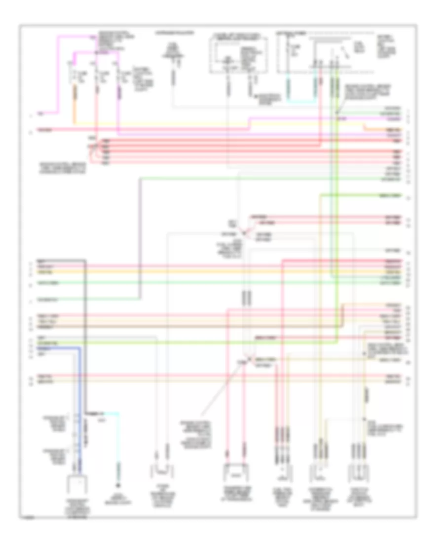
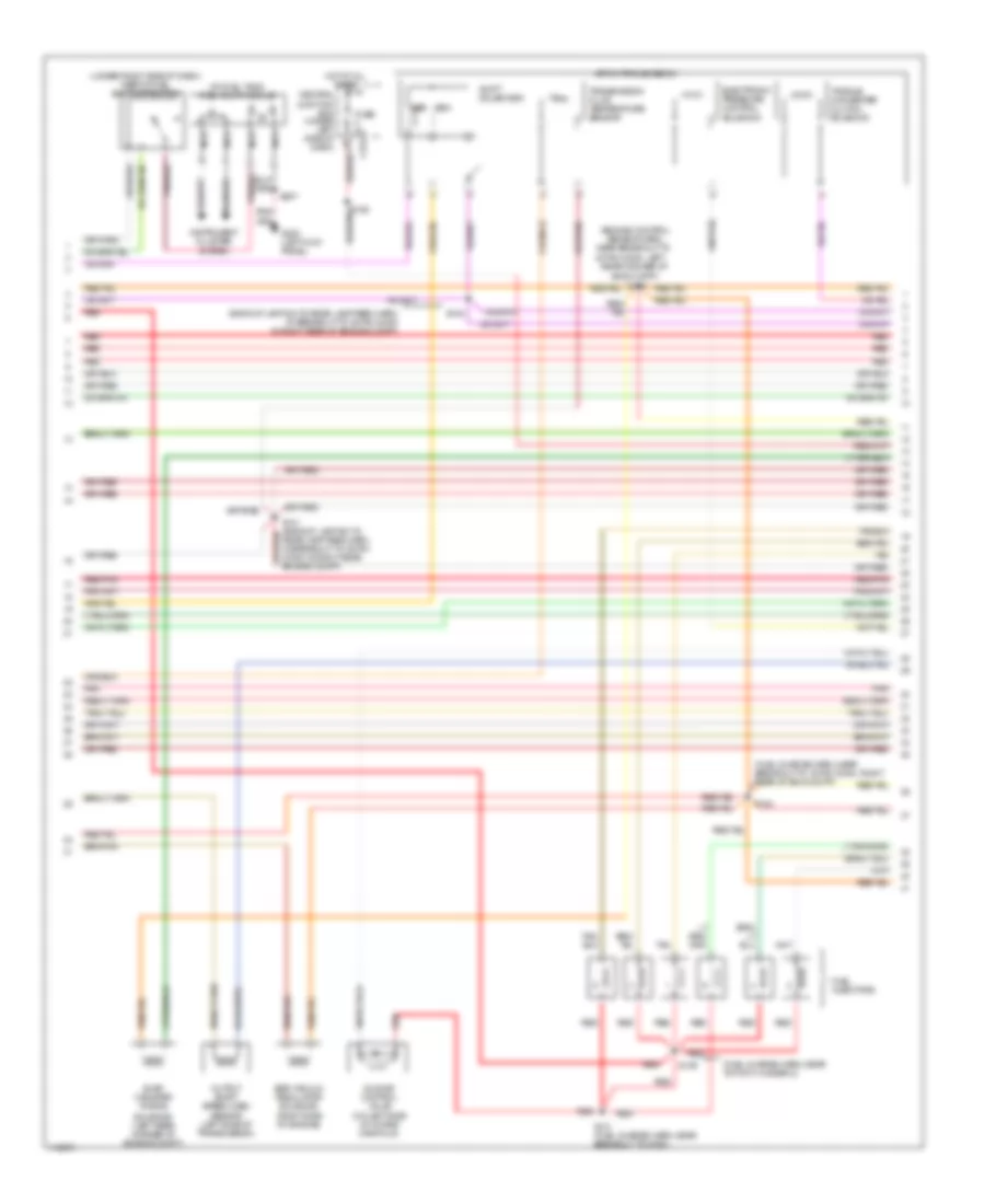
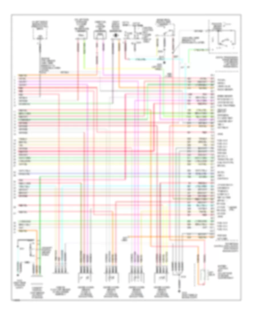
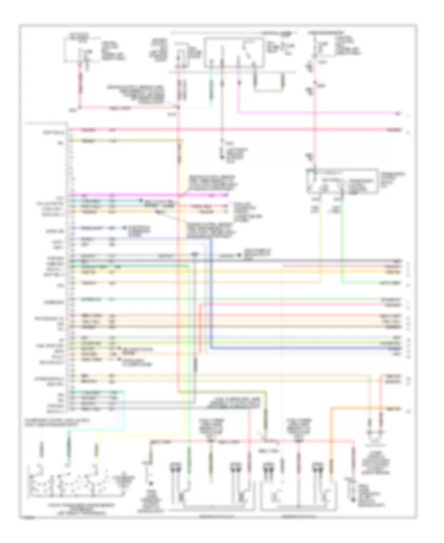
5.4L 5.4L CNG, Engine Performance Wiring Diagrams (1 of 5) for Ford Pickup F350 Super Duty 1999 List of elements for 5.4L CNG, Engine Performance Wiring Diagrams (1 of 5) for Ford Pickup F350 Super Duty 1999: 58 (eng ctrl sensor harn, near breakout to 12-pin conn, center front of eng compt) (left front radiator support) g108 (under center of dash) (partial) data link connector A/c on sig Air conditioning system Battery junction box (left side of engine compt) Case gnd Ccs Central junction box (under left side of dash) Ckp (+) Ckp (-) Data link (+) Data link (-) Digital transmission range sensor (dtr sensor) (left side of transmission) Dlc Dtr-tr1 Dtr-tr2 Dtr-tr4 Fuel pump mon Fuse 30a Fuse 5a G123 (right rear of engine compt) G200 (lower left kick panel) Hot at all times Hot in run or start Iat Ign coil 1 Ign coil 3 Ign coil 5 Ign coil 6 Imcc Maf Nca Ngv timer (left rear of engine compt) O/d off Ohms Pcm power diode Pcm power relay Powertrain control module (right side of engine compt) Pwr gnd R n S100 S106 S116 S156 S157 S207 S225 Ss1 Ss2 Starting/ charging system Tan/red Tcil ind Tcs Tft To dtr sensor (diagram 5 of 5) Transmission control indicator lamp Transmission control switch 5.4L CNG, Engine Performance Wiring Diagrams (2 of 5) for Ford Pickup F350 Super Duty 1999 List of elements for 5.4L CNG, Engine Performance Wiring Diagrams (2 of 5) for Ford Pickup F350 Super Duty 1999: 37 (engine control sensor harn, near breakout to 40-pin conn in left rear of engine compt) (fuel charge harn, near breakout to fuel inj 8) (fuel tank harn, near breakout to tank valve 2) s302 (under left side of dash) central junction box Battery junction box (left side of engine compt) C236 C237 C243 C267 Crankshaft position (ckp) sensor (lower front of engine) Crankshaft position sensor shield Electronic suspension system Forward in-bed fuel tank valve (at fuel tank) Fuel gauge Fuel reset switch indicator Fuse 15a G108 (left front radiator support) G123 (right rear of engine compt) Generic electronic module/ central timer module Inertia fuel shut-off switch (under right side of dash) Injection pressure sensor (ips) (on top of engine) Instrument cluster Intake air temperature (iat) sensor (on intake manifold) Midship fuel tank valve (at fuel tank) Nca Rear in-bed fuel tank valve (at fuel tank) Red Red/pnk S101 S135 S136 (fuel charge harn, near breakout to ing coil 4) S139 S159 (engine ctrl sensor harn, near breakout to wiper motor) S199 S301 Throttle position (tp) sensor (on throttle body) Vss input 5.4L CNG, Engine Performance Wiring Diagrams (3 of 5) for Ford Pickup F350 Super Duty 1999 List of elements for 5.4L CNG, Engine Performance Wiring Diagrams (3 of 5) for Ford Pickup F350 Super Duty 1999: 25 (backup lamp harn, at breakout to 38-pin conn in right rear of engine compt) Battery junction box (left side of engine compt) Coast clutch solenoid Electronic pressure control solenoid Fuel rail cutoff valve (on fuel rail) Fuel shutoff valve relay Fuse 20a G117 (lower right rear of engine) Hot at all times Ignition coils Nca R4100 transmission Radio noise capacitor (on top left side of engine) Radio noise capacitor (on top right side of engine) Red Red red Red/pnk S117 (fuel charge harn, near breakout to 42-pin inline conn in right rear of engine compt) S140 S153 S161 (fuel charge harn, in breakout to injector 3) S162 (fuel charge harn, in breakout to injector 7) Shift solenoid Torque converter clutch solenoid Transmission fluid temperature sensor 5.4L CNG, Engine Performance Wiring Diagrams (4 of 5) for Ford Pickup F350 Super Duty 1999 List of elements for 5.4L CNG, Engine Performance Wiring Diagrams (4 of 5) for Ford Pickup F350 Super Duty 1999: 42 (eng control sens harn, near breakout to wiper motor) Data (+) Data (-) Fuel gauge Fuel injectors Fuel press Fuel temp Ground Ignition Inj 1 input Inj 1 out Inj 2 input Inj 2 out Inj 3 input Inj 3 out Inj 4 input Inj 4 out Inj 5 input Inj 5 out Inj 6 input Inj 6 out Inj 7 input Inj 7 out Inj 8 input Inj 8 out Intake manifold communicator control (imcc) (right side of engine) Ngv fuel tank pressure sensor (at fuel tank) Ngv fuel tank temperature sensor (at fuel tank) Ngv module (on front of engine) Output shaft speed (oss) sensor (on left side of transmission) Power Red Red/pnk S127 S129 (fuel charge harn, near breakout to ign coil 3) S131 (fuel charge harn, near breakout ign coil 7) S303 (fuel tank harn, near fuel tank) Sig return Tan Tan/ red Tan/red Timer 5.4L CNG, Engine Performance Wiring Diagrams (5 of 5) for Ford Pickup F350 Super Duty 1999 List of elements for 5.4L CNG, Engine Performance Wiring Diagrams (5 of 5) for Ford Pickup F350 Super Duty 1999: 73 (eng cntrl sens harn) (engine control sensor harn, near breakout to windshield wiper motor) (engine control sensor harn, right rear of engine compt) (fuel charge harness) (left rear of trans) turbine shaft speed sensor (left side of engine compt) speed control servo (main harn, near breakout to instrument cluster) (top front of left head) cylinder head temperature sensor 270 ohms 5v ref Battery junctioin box (in left side of engine compt) Bpp switch Brake pedal position (bpp) switch C242 C243 Camshaft position (cmp) sensor (on front of engine) Camshaft position sensor shield Central junction box (under left side of dash) Cmp sensor Cyl head temp Digital transmission range sensor (dtr sensor-a/t) (left side of transmission) Dtr-tr3a Eft sensor Engine fuel temperature (eft-a) sensor (on top of engine) Epc sol From dtr sensor (diagram 1 of 5) Fuel ctrl Fuse 5a G123 (right rear of engine compt) G200 (lower left kick panel) Heated oxygen sensor (ho2s) 11 (on engine exhaust pipe) Heated oxygen sensor (ho2s) 21 (on engine exhaust pipe) Ho2s (11) Ho2s (21) Ho2s sig (#11) Ho2s sig (21) Hot at all times Idle air control valve (on left side of intake manifold) Idle air ctrl Ign coil 2 Ign coil 4 Ign coil 7 Ign coil 8 Inj pressure Kap b(+) Maf sens in Mass air flow (maf) sensor (in air cleaner assembly) Nca Ngv module Not used Oss sensor Powertrain control module (right side of engine compt) Pwr gnd Red Red/pnk S100 S101 S138 S141 S143 S154 S155 S158 S199 Sig rtn Tcc sol Tp sens in Tss sensor Vpwr Vss (+) Vss input Wire terminates in harness Wot relay 5.4L, Engine Performance Wiring Diagrams (1 of 4) for Ford Pickup F350 Super Duty 1999 List of elements for 5.4L, Engine Performance Wiring Diagrams (1 of 4) for Ford Pickup F350 Super Duty 1999: 69 (engine control sensor harn, near breakout to 12-pin conn, center front of engine compartment) (engine control sensor harn, near breakout to 40-pin connector, left rear left rear corner of eng compt) (fuel charge harn, near breakout to fuel injector 3) (left front radiator support) g108 (right rear of engine compt) g123 4x4 low ind sw 820 ohms Accs Air conditioning system Battery junction box (left side of engine compt) Body computer system C243 Case gnd Ccs Central junction box (under left side of dash) Ckp(+) Ckp(-) Data link (+) Data link (-) Data link connector (partial) (under center of dash) Digital transmission range sensor (dtr sensor) (left side of transmission) Dlc Evr ctrl Fuel pump mon Fuse 30a Fuse 5a Hot at all times Hot in run or start Iat Ign coil 1 Ign coil 3 Ign coil 5 Ign coil 6 Ignition coils Intake manifold Intake manifold communicator (imcc) control (on right side of engine) Ks sensor Maf Nca O/d off Pcm power diode Pcm power relay Pnk Powertrain control module (pcm) (right side of engine compt) Pwr gnd R n Radio noise capacitor (on top right side of engine) Radio noise capacitor 2 (on top left side of engine) Rr ho2s sig (12) S100 S106 S116 S117 (fuel charge harn, near breakout to 42-pin conn in right rear of engine compt) S156 S157 S161 S225 S237 Shift sol Tc spd sens Tcs Tft To dtr sensor (diagram 4 of 4) Tr1 Tr2 Tr4 Trans ctrl ind Transmission control indicator lamp Transmission control switch (a/t) 5.4L, Engine Performance Wiring Diagrams (2 of 4) for Ford Pickup F350 Super Duty 1999 List of elements for 5.4L, Engine Performance Wiring Diagrams (2 of 4) for Ford Pickup F350 Super Duty 1999: 37 (eng control sens harn, near breakout to starter mtr relay) s137 (engine control sensor harn, near breakout to 4-pin conn in right rear corner of engine compt) (engine control sensor harn, near breakout to 40-pin conn in left rear of engine compt) (engine control sensor harn, near breakout to windshield wiper motor) (under left side of dash) central junction box Battery junction box (left side of engine compt) Breakout to battery junction box) s1003 C236 C267 Crankshaft position (ckp) sensor (lower front of engine) Crankshaft position sensor shield Differential pressure feedback egr (dpfe) sensor (left side of engine) Electronic suspension system Fuel pump relay Fuel reset switch indicator Fuel tank pressure sensor (at fuel tank) Fuse 15a Fuse 20a G123 (rear of engine compt) Generic electronic module/ central timer module Hot at all times Instrument cluster Intake air temperature (iat) sensor (on intake manifold) Nca Pnk Red Red/pnk S101 S127 S135 (fuel charge harn, near breakout to fuel inj 8) S136 (fuel charge harn, near breakout to ing coil 4) S138 S139 Throttle position (tp) sensor (on throttle body) Transfer case speed sensor (at left rear of transmission) Turbine shaft speed (tss) sensor (at left rear of transmission) Vss input 5.4L, Engine Performance Wiring Diagrams (3 of 4) for Ford Pickup F350 Super Duty 1999 List of elements for 5.4L, Engine Performance Wiring Diagrams (3 of 4) for Ford Pickup F350 Super Duty 1999: 39 (at fuel tank) fuel pump module (backup lamp sw to rear lamp feed harn, at breakout to 38-pin conn in right rear of engine compt) (eng cntrl sens harn, left rear corner of eng compt) s155 (fuel charge harn, near breakout to 16-pin conn, right rear of eng compt) (fuel charge harn, near breakout to ignition coil 3) (under right side of dash) inertia fuel shut-off switch 4r100 4r70w Central junction box (under left side of dash) Coast clutch solenoid (4r100) Egr vacuum regulator solenoid (left side of engine) Electronic pressure control solenoid Evap canister purge Fuel injectors Fuse 5a G200 (left kick panel) Hot at all times Idle air control valve (on left side of intake manifold) Instrument cluster system Nca Output shaft speed (oss) sensor (left side of transmission) Rear lamp feed harn, in breakout to 38-pin conn in right rear engine compt) Red Red/pnk S129 S131 (fuel charge harn, near breakout to ign coil 7) S140 S154 S207 Shift solenoid (4r70w) Shift solenoid 1 (4r100) Shift solenoid 2 (4r100) Tan Tan/ red Tan/red Torque converter clutch solenoid Transmission Transmission fluid temperature sensor Valve (left rear corner of engine compt) 5.4L, Engine Performance Wiring Diagrams (4 of 4) for Ford Pickup F350 Super Duty 1999 List of elements for 5.4L, Engine Performance Wiring Diagrams (4 of 4) for Ford Pickup F350 Super Duty 1999: 83 (engine ctrl sensor harn, near breakout to windsheild wiper motor) s143 (in left side of engine compt) speed control servo (main harn, near breakout to instrument cluster) (near fuel tank) canister vent solenoid (on left side of engine compartment) (right side of engine) knock sensor (ks) (top front of engine) cylinder head temperature sensor 5.4l 2v only 5v ref volt A/t Battery junction box Bpp sw Brake pedal position (bpp) switch Cam pos in Camshaft position (cmp) sensor (on front of engine) Camshaft position sensor shield Canister vent Central junction box (under left side of dash) Cyl head temp Digital transmission range sensor (dtr sensor) (left side of transmission) Dpfe sens Epc sol From dtr sensor (diagram 1 of 4) Fuel inj 1 Fuel inj 2 Fuel inj 3 Fuel inj 4 Fuel inj 5 Fuel inj 6 Fuel inj 7 Fuel inj 8 Fuel pump ctrl Fuel tank press Fuse 5a G123 (right rear of engine compt) G123 (right rear of engine compt) G200 (left kick panel) Heated oxygen sensor (ho2s) 11 (on engine exhaust pipe) Heated oxygen sensor (ho2s) 12 (on engine exhaust pipe) Heated oxygen sensor (ho2s) 21 (on engine exhaust pipe) Heated oxygen sensor (ho2s) 22 (on engine exhaust pipe) Heater ctrl Ho2s 11 Ho2s 12 Ho2s 21 Ho2s 22 Hot at all times Hot in start Iac sol Ign coil 2 Ign coil 4 Ign coil 7 Ign coil 8 Kap b(+) Knock sensor Lf ho2s sig (21) Lr ho2s sig (22) M/t Maf sens in Mass air flow (maf) sensor (in air cleaner assembly) Nca Oss (+) Powertrain control module (pcm) (right side of engine compt) Pwr gnd Red Red/pnk Rf ho2s sig (11) S100 S101 S208 S297 Sig return Tan Tan/red Tcc sol Tp sens in Tr3a (a/t) bpp (m/t) Tss spd sens Vapor valve Vpwr Vss (+) Vss input Wot relay
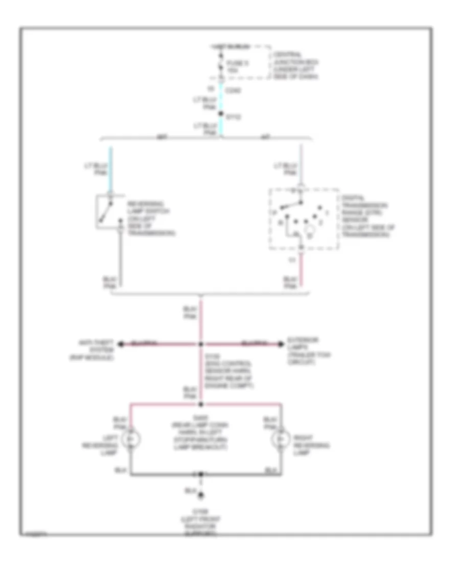
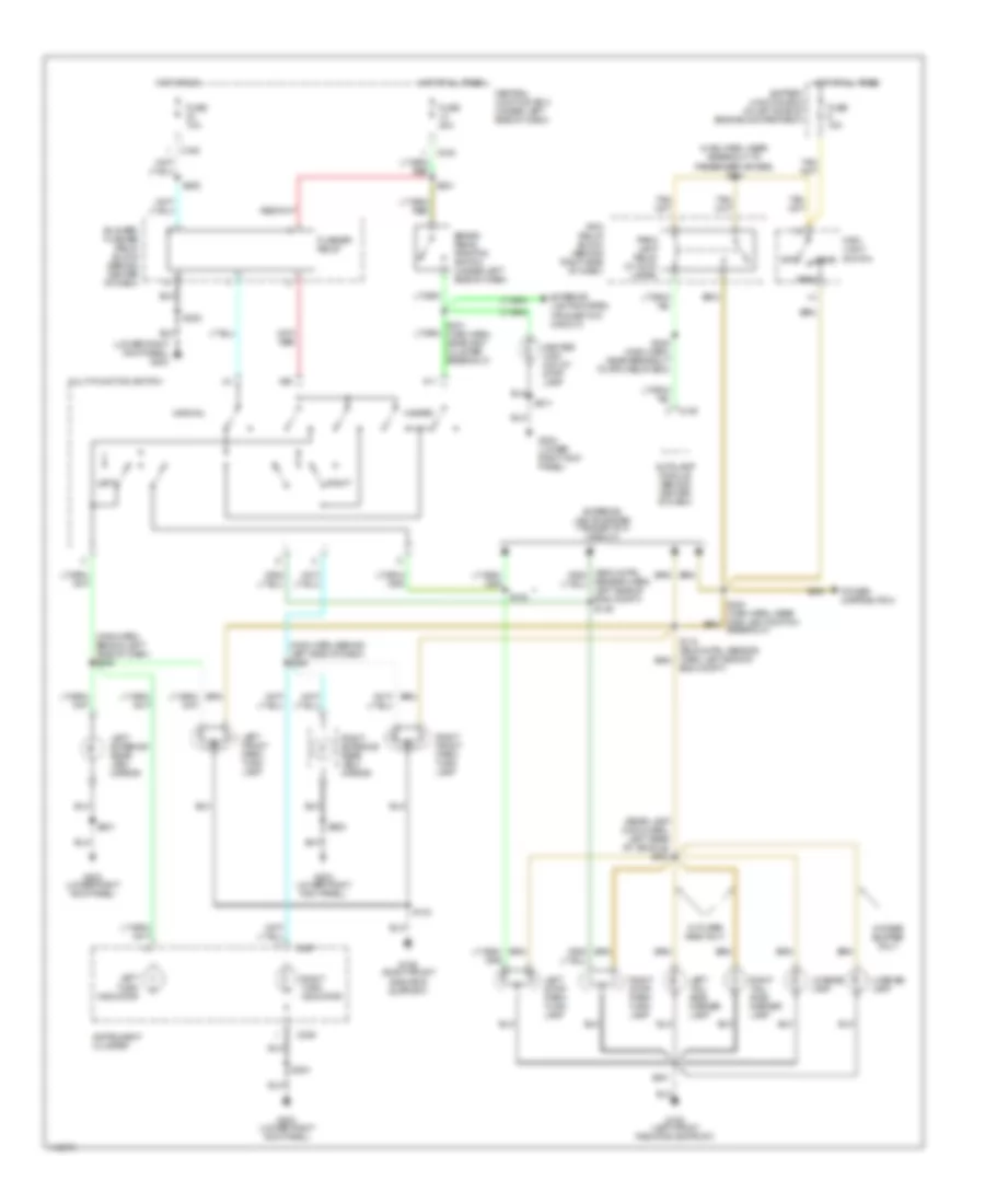
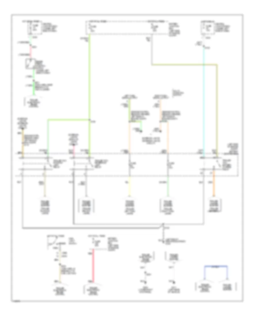
EXTERIOR LIGHTS Back-up Lamps Wiring Diagram for Ford Pickup F350 Super Duty 1999 List of elements for Back-up Lamps Wiring Diagram for Ford Pickup F350 Super Duty 1999: 19 A/t Anti-theft system (rap module) C242 Central junction box (under left side of dash) Digital transmission range (dtr) sensor (on left side of transmission) Exterior lamps (trailer tow circuit) Fuse 5 15a G108 (left front radiator support) Hot in run Lamp Left M/t Reversing Reversing lamp switch (on left side of transmission) Right reversing lamp S112 S130 (eng control sensor harn, right rear of engine compt) S401 S405 (rear lamp conn harn, in left stop/park/turn lamp breakout) Exterior Lamps Wiring Diagram for Ford Pickup F350 Super Duty 1999 List of elements for Exterior Lamps Wiring Diagram for Ford Pickup F350 Super Duty 1999: 66 (lower right kick panel) g203 (main harn, behind left side of dash) s246 (main harn, near breakout to passenger air bag) s241 (rear lamp conn harn, left rear of vehicle) s403 Autolamp module (behind center of dash) Battery junction box (in left side of engine compartment) Blower/ flasher relay block (behind center of dash) Brake pedal position switch (under left side of dash) Breakout) C216 C236 C237 C242 C243 Center high mount stop lamp Central junction box (under left side of dash) Eng compt) Exterior lights system (trailer tow circuit) Flasher relay Fuse 10a Fuse 15a Fuse 20a G108 (left front radiator support) G109 (right front G203 (lower right kick panel) Hazard Head Hot at all times Hot in run Instrument cluster Left Left exterior rear view mirror Left front park/ turn lamp Left stop/ park/ turn lamp Left tail/ side marker lamp Left turn indicator License lamp Main light switch Multi-function switch Normal Off Park Park lamp relay (w/ auto lamps) Power distribution Radiator support) Right Right exterior rear view mirror Right front park/ turn lamp Right stop/ park/ turn lamp Right tail/ side marker lamp Right turn indicator Rpo relay block (behind right side of dash) S104 S148 S202 S204 S221 S228 S245 (main harn, near breakout to rpo relay box) S401 S501 S600 S911 Sensor harn, left side of eng compt) s149 W/ flare side only W/ rear bumper only Trailer/Camper Adapter Wiring Diagram for Ford Pickup F350 Super Duty 1999 List of elements for Trailer/Camper Adapter Wiring Diagram for Ford Pickup F350 Super Duty 1999: 46 (1999) (2000) (engine cntrl sensor harn, left side of eng compt) s115 (engine control sensor harness, left side of engine compt) s148 (engine control sensor harness, left side of engine compt) s149 (left front radiator support) g108 (left side of engine compt) battery junction box (trailer backup lamps) (trailer battery) (trailer left turn lamps) (trailer right turn lamps) (trailer running lamps) Battery junction box (left side of engine compt) Brake pedal position switch (under left side of dash) Breakout to inst cluster) C242 C243 Central junction box (under left side of dash) Exterior lights (back-up lamps circuit) Exterior lights (exterior lights circuit) Fuse 10a Fuse 20a Fuse 30a G203 (lower right kick panel) G411 (left rear of vehicle) Head Hot at all times Hot in run Left turn signal output Main light switch Multi- function switch Off Park Red Right turn signal output S105 S108 S120 S201 S221 S224 (main harn, in breakout to main light sw) Trailer electronic brake control Trailer tow battery charge relay Trailer tow reversing lamp relay Trailer tow running lamp relay Trailer/ camper adapter
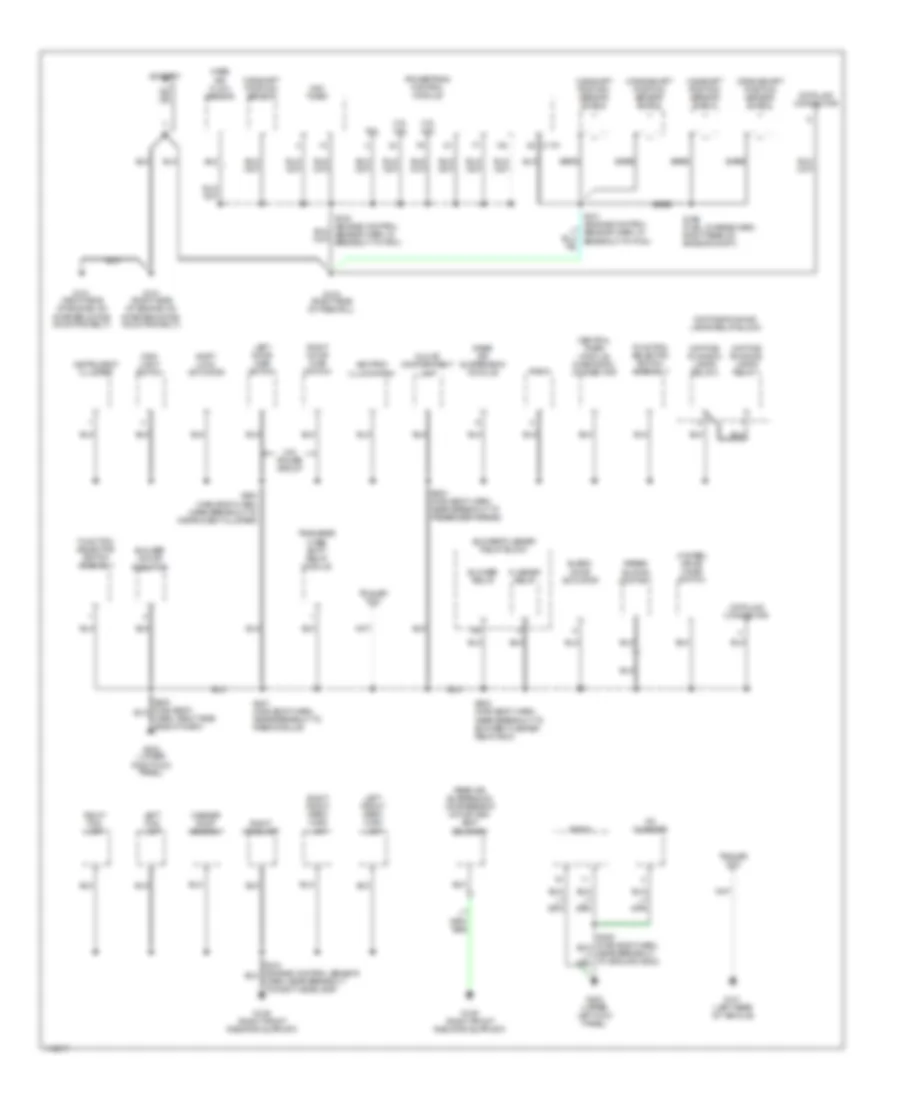
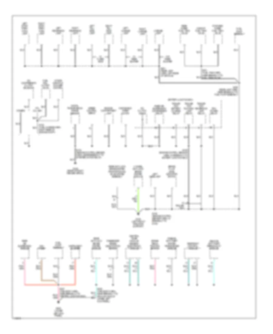
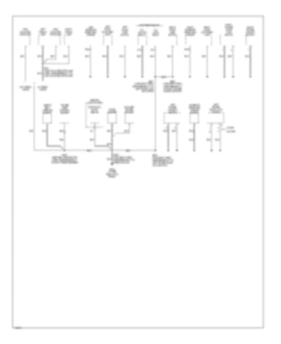
GROUND DISTRIBUTION Ground Distribution Wiring Diagram (1 of 3) for Ford Pickup F350 Super Duty 1999 List of elements for Ground Distribution Wiring Diagram (1 of 3) for Ford Pickup F350 Super Duty 1999: 57 4 wheel drive mode switch 4.2l 4.6l 5.4l Airbag sliding contact Ashtray illumination Bare Battery Blend door actuator Blower motor resistor Blower relay Blower/flasher relay block C174 Camshaft position sensor Camshaft position sensor shield Cd changer Central timer module diagnostic connector Crankshaft position sensor shield Data link connector Daytime running lamps relay 1 Daytime running lamps relay 2 Daytime running lamps relay block Flasher relay Function selector switch assembly G101 (right side of engine, on starter motor mounting bolt) G109 (right front radiator suppurt) G123 (right side of firewall) G202 (upper left kick panel) G203 (lower right kick panel) G411 (left rear of vehicle) Glove compartment lamp Harn, near breakout to right headlamp) Harn, right side side of dash) Instrument cluster Left door ajar switch Left fog lamp Left front park/ turn lamp Main light switch Mass air flow sensor Ngv timer Powertrain control module Radio Rear air suspension compressor motor and vent solenoid Rear air suspension module Right door ajar switch Right fog lamp Right front park/ turn lamp Right headlamp S199 (fuel charge harn, right rear of engine compt) S201 (main body harn, near breakout to rabs module) S202 (main body harn, near breakout to blower/ flasher relay box) S203 (main body harn, near breakout to passenger airbag) S204 (main body harn, near breakout to instrument cluster) Shift lock actuator Trailer tow Transfer case shift relay module W/o power group Washer pump assembly Ground Distribution Wiring Diagram (2 of 3) for Ford Pickup F350 Super Duty 1999 List of elements for Ground Distribution Wiring Diagram (2 of 3) for Ford Pickup F350 Super Duty 1999: 55 4 wheel anti-lock brake system module 4.2l, 5.4l ngv A/c clutch diode A/c compressor clutch solenoid Battery junction box Brake fluid level indicator switch Brake pedal position switch Central timer module/ generic electronic module Digital transmission range sensor Engine compartment lamp Forward in-bed fuel tank valve Fuel pump assembly Fuel rail cutoff valve G105 (rear of right fender apron) G108 (left front radiator support) G200 (lower left kick panel) Instrument cluster Intake manifold runner control Left headlamp Left license lamp Left reversing lamp Left stop/ park/ turn lamp Left tail/ side lamp License lamp Midship fuel tank valve Ngv timer Others Passenger airbag deactivation switch Passive anti-theft system transceiver module Pcm power relay Rear air suspension compressor relay Rear air suspension module Rear anti-lock brake system module Rear anti-lock brake system proportioning valve system assembly Rear in-bed fuel tank valve Remote anti-theft personality module Restraint control module Right license lamp Right rear of engine compt) Right reversing lamp Right stop/ park/ turn lamp Right tail/ side lamp S102 (engine control sensor harn, near breakout to starter motor relay) S105 (engine control sensor harn, in breakout to battery junction box) S106 (engine control sensor harn, in breakout to g108) S400 (rear lamp harn, near breakout to fuel pump assembly) Speed control servo Trailer tow battery charge relay Trailer tow reversing lamp relay Trailer tow running lamp relay W/ flare side W/ rear bumper W/ trailer tow W/o rear bumper Windshield wiper motor Ground Distribution Wiring Diagram (3 of 3) for Ford Pickup F350 Super Duty 1999 List of elements for Ground Distribution Wiring Diagram (3 of 3) for Ford Pickup F350 Super Duty 1999: 35 87a All lock relay All unlock relay Auxiliary power socket Central junction box Cigar lighter Exterior rear view mirror switch G203 (lower right kick panel) High mounted stoplamp High mounted stoplamp) Left cargo lamp Left door ajar switch Left door courtesy lamp Left exterior rear view mirror Left power door lock switch Left power window switch Lock relay block Near breakout to right power window switch) One touch down relay Power seat control switch Right cargo lamp Right door ajar switch Right door courtesy lamp Right exterior rear view mirror Right power door lock switch Right power window switch S304 (seat belt retractor harn, near breakout to right rear speaker) S500 (main body harn, near breakout to left power door lock switch) S501 (main body harn, near breakout to left door lock actuator) S600 (main body harn, Safety belt warning switch W/ cargo lamps W/ rap W/o cargo lamps W/o rap
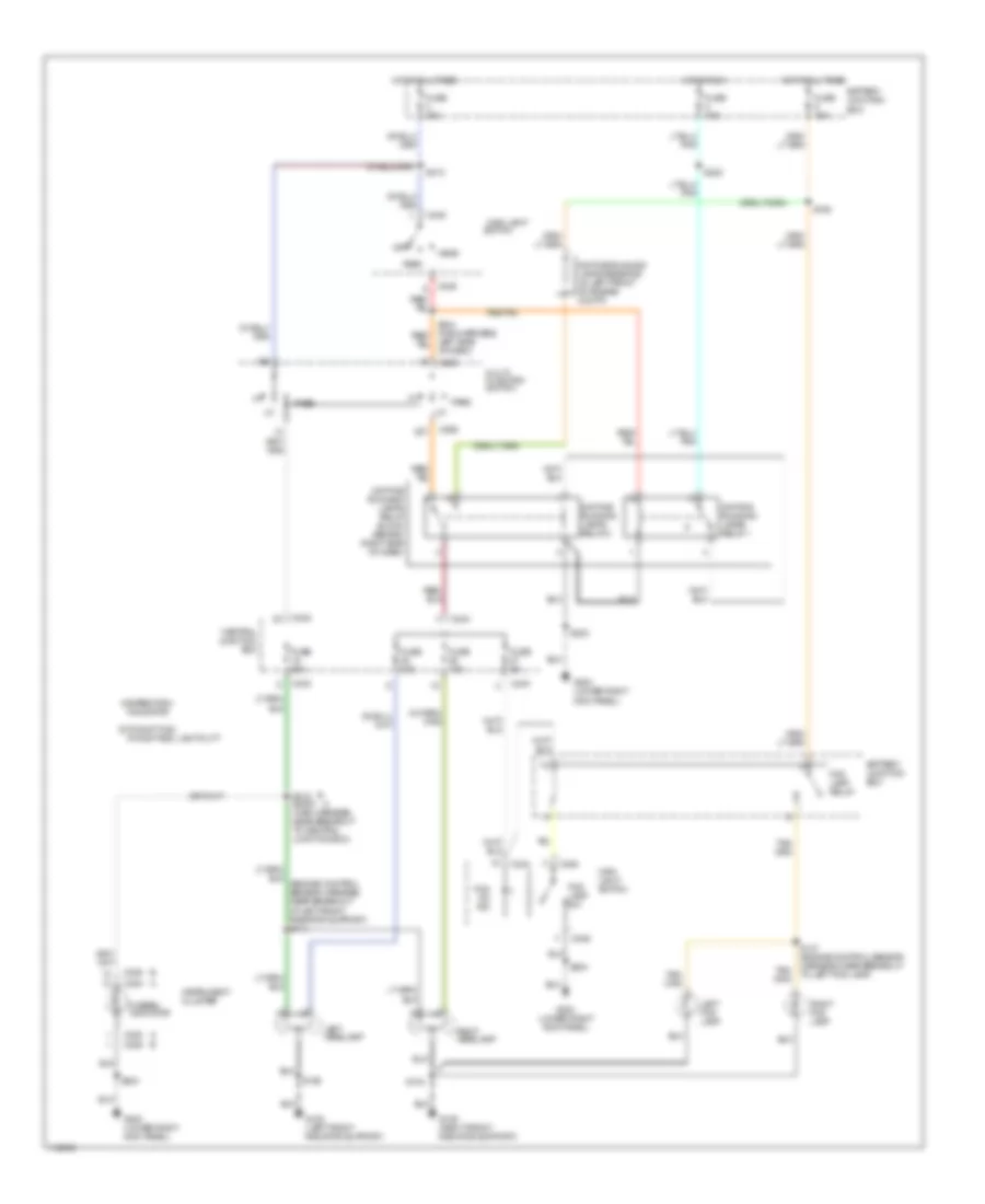
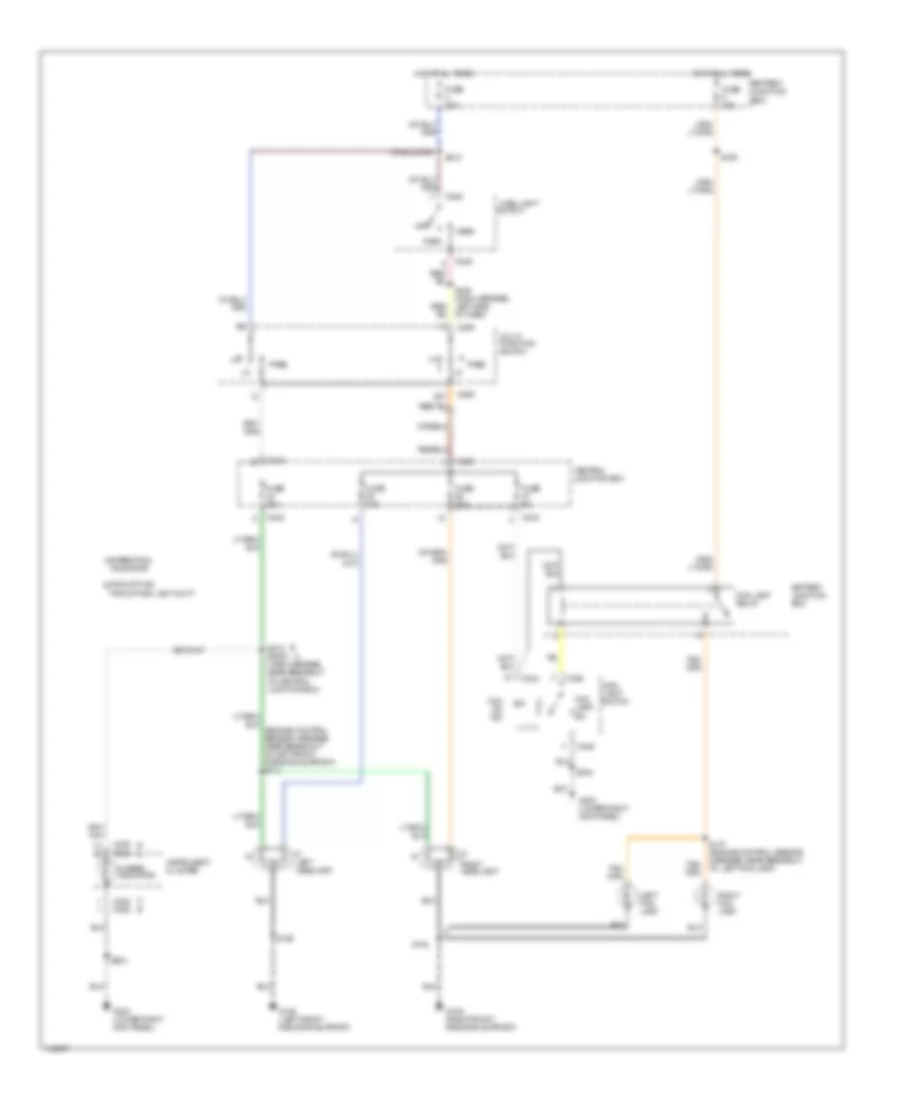
HEADLIGHTS Autolamps & Fog Lamps Wiring Diagram, with DRL for Ford Pickup F350 Super Duty 1999 List of elements for Autolamps & Fog Lamps Wiring Diagram, with DRL for Ford Pickup F350 Super Duty 1999: 74 (engine control sensor harness, near breakout at left front radiator support) s114 (engine control sensor harness, near breakout to left fog lamp) s147 (lower right kick panel) g203 (main harness, near breakout to central junction box) s2000 s218 (main harness, near breakout to passenger airbag) (main harness, near breakout to rpo relay block) s245 A expedition/ navigator Auto- lamp on Auto-lamp on ind Autolamp module (behind center of dash) B pickup f150/ pickup f250 light duty Battery Battery junction box C236 C238 C242 C243 C244 C245 C246 C257 C259 Central junction box Cntrl sw out Daytime running lamps relay 1 Daytime running lamps relay 2 Daytime running lamps relay block (behind right side of dash) Daytime running lamps resistor (in left front of engine compt) Exterior lights system, trailer/ camper adapter Fog lamp relay Fog lamp sw Fog on ind Fuse 10a Fuse 15a Fuse 20a Fuse 30a Fuse 5a G108 (left front radiator support) G109 (right front radiator support) G203 (lower right kick panel) Head Headlamp relay Hi-beam indicator Hot at all times Hot in run Hot in start or run Ignition Instrument cluster Left fog lamp Left headlamp Main light switch Multi- function switch Off Park Park lamp relay Pass Relay output Remote anti-theft personality module (behind left side of dash) Rheostat out Right fog lamp Right headlamp Rpo relay box (behind right side of dash) S104 S106 S109 S2013 S203 S204 S212 S219 S222 S225 S241 S244 (main harness, left side of dash) Autolamps & Fog Lamps Wiring Diagram, without DRL for Ford Pickup F350 Super Duty 1999 List of elements for Autolamps & Fog Lamps Wiring Diagram, without DRL for Ford Pickup F350 Super Duty 1999: 70 (main harness, near breakout to central junction box) s2000 s218 (main harness, near breakout to passenger airbag) (main harness, near breakout to rpo relay block) s245 A b A expedition/ navigator Auto- lamp on Auto- lamp on ind Autolamp module (behind center of dash) B a B pickup f150/ pickup f250 light duty Battery Battery junction box C236 c238 C238 c236 C242 C243 C244 C245 C246 C257 C259 Central junction box Cntrl sw out Exterior lights system, trailer/ camper adapter Fog lamp relay Fog lamp sw Fog on ind Fuse 10a Fuse 15a Fuse 20a Fuse 30a Fuse 5a G108 (left front radiator support) G109 (right front radiator support) G203 (lower right kick panel) Head Headlamp relay Hi-beam indicator Hot at all times Hot in start or run Ignition Instrument cluster Junction box fuse/relay panel Left fog lamp Left headlamp Main light Main light switch Multi- function switch Off Park Park lamp relay Pass Relay output Remote anti-theft personality module (behind left side of dash) Rheostat out Right fog lamp Right headlamp Rpo relay box (behind right side of dash) S104 S106 S109 S147 (engine control sensor harness, near breakout to left fog lamp) S204 S212 S219 S224 S225 S241 s2013 S244 (main harn, near left side of dash) Switch Headlamps & Fog Lamps Wiring Diagram, with DRL for Ford Pickup F350 Super Duty 1999 List of elements for Headlamps & Fog Lamps Wiring Diagram, with DRL for Ford Pickup F350 Super Duty 1999: 53 A expedition/ navigator Battery junction box C236 C238 C242 C243 C244 C246 C259 Central junction box Daytime running lamps relay 1 Daytime running lamps relay 2 Daytime running lamps relay block (behind right side of dash) Daytime running lamps resistor (in left front of engine compt) Fog lamp relay Fog lamp sw Fog on ind Fuse 10a Fuse 15a Fuse 20a Fuse 30a Fuse 5a G108 (left front radiator support) G109 (right front radiator support) G203 (lower right kick panel) Head Hi-beam indicator Hot at all times Hot in run Instrument cluster Left fog lamp Left headlamp Left side of dash) Main light Main light switch Multi- function switch Off Park Pass Pickup f150/ b Pickup f250 light duty Right fog lamp Right headlamp S104 S106 S109 S147 (engine control sensor harness, near breakout to left fog lamp) S203 S204 S212 S218 s2000 (main harness, near breakout to central junction box) S222 Switch Headlamps & Fog Lamps Wiring Diagram, without DRL for Ford Pickup F350 Super Duty 1999 List of elements for Headlamps & Fog Lamps Wiring Diagram, without DRL for Ford Pickup F350 Super Duty 1999: 44 A expedition/ navigator pickup f150/ b pickup f250 light duty Battery junction box C236 c238 C238 c236 C242 C243 C244 C246 C259 Central junction box Fog lamp relay Fog lamp sw Fog on ind Fuse 10a Fuse 15a Fuse 20a Fuse 30a Fuse 5a G108 (left front radiator support) G109 (right front radiator support) G203 (lower right kick panel) Head Hi-beam indicator Hot at all times Instrument cluster Left fog lamp Left headlamp Main light Main light switch Multi- function switch Off Park Pass Right fog lamp Right headlamp S104 S106 S109 S147 (engine control sensor harness, near breakout to left fog lamp) S204 S212 S218 s2000 (main harness, near breakout to central junction box) S244 (main harness, left side of dash) Switch
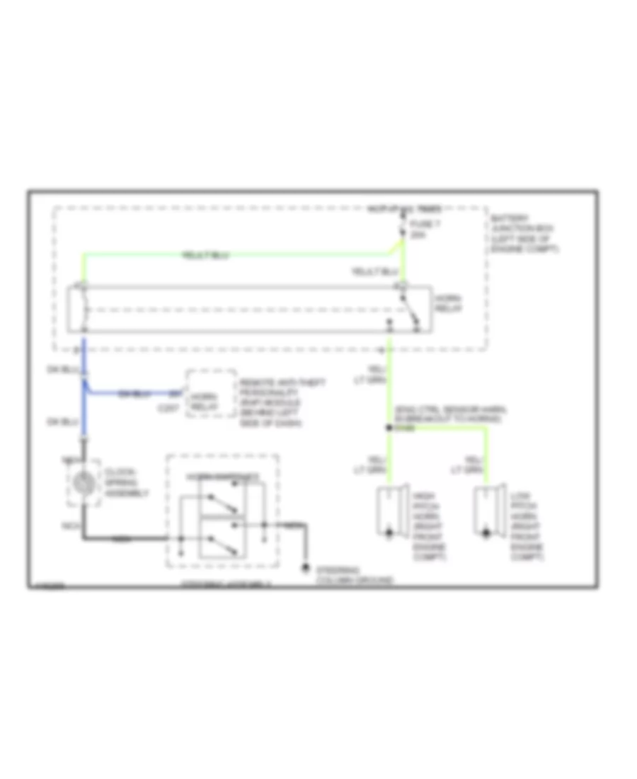
HORN Horn Wiring Diagram for Ford Pickup F350 Super Duty 1999 List of elements for Horn Wiring Diagram for Ford Pickup F350 Super Duty 1999: 14 (eng ctrl sensor harn, in breakout to horns) s145 Battery junction box (left side of engine compt) C257 Clock- spring assembly Fuse 7 20a High pitch horn (right front engine compt) Horn relay Horn switches Hot at all times Low pitch horn (right front engine compt) Nca Remote anti-theft personality (rap) module (behind left side of dash) Steering assembly Steering column ground
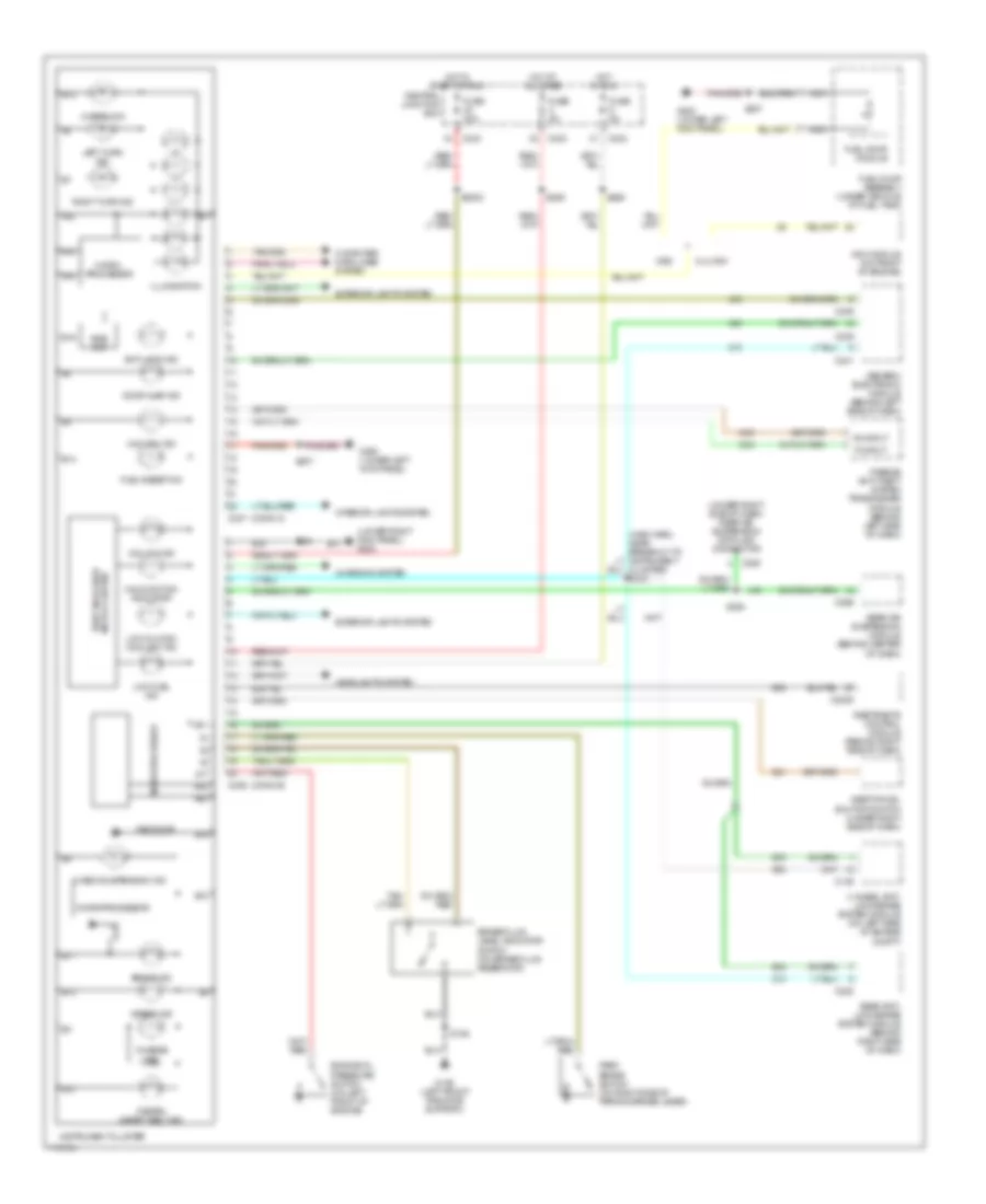
INSTRUMENT CLUSTER Instrument Cluster Wiring Diagram for Ford Pickup F350 Super Duty 1999 List of elements for Instrument Cluster Wiring Diagram for Ford Pickup F350 Super Duty 1999: 92 (conn a) (conn b) (lower right kick panel) g203 (main harn, near breakout to instrument cluster) s232 (under right side of dash) rear air suspension data link connector 4 wheel anti- lock brake system module (on left side of engine compt) 4x4 high ind 4x4 low ind 5.4l ngv 820 ohms A10 A14 A15 A17 A22 Airbag ind Anti-lock ind B10 B11 B12 B13 B14 B16 B17 B18 B19 B20 Bias ckt Brake fluid level indicator switch (on brake fluid reservoir) Brake ind C146 C2005 C222 C236 C237 C239 C241 C242 C243 C285 C296 Central junction box Charge ind Charging system Check suspension ind Computer data lines system Door ajar ind Engine oil pressure switch (on left front of engine) Exterior lights system Fasten safety belt ind Fuel pump assembly (under vehicle, at fuel tank) Fuel pump module Fuel reset ind Fuse 30a Fuse 5a G108 (left front radiator support) G200 (lower left kick panel) Gas Generic electronic module (behind left side of dash) Headlights system Hi beam ind Hot at all times Hot in run Hot in start or run Illumination Inertia fuel shutoff switch (under right side of dash) Instrument cluster Interior lights system Left turn ind Low fuel ind Low oil/high coolant ind Malfunction indicator Micro- processor Microprocessor Nca Ngv module (on front of engine) Park brake switch (on right side of parking brake lever) Passive anti-theft system transceiver module (behind left side of dash) Rear air suspension module (behind center of dash) Rear anti- lock brake system module (behind right side of dash) Restraints control module (behind right side of dash) Right turn ind Rx input S106 S2002 S204 S207 S265 S289 S294 Theft indicator micro cluster Tx input
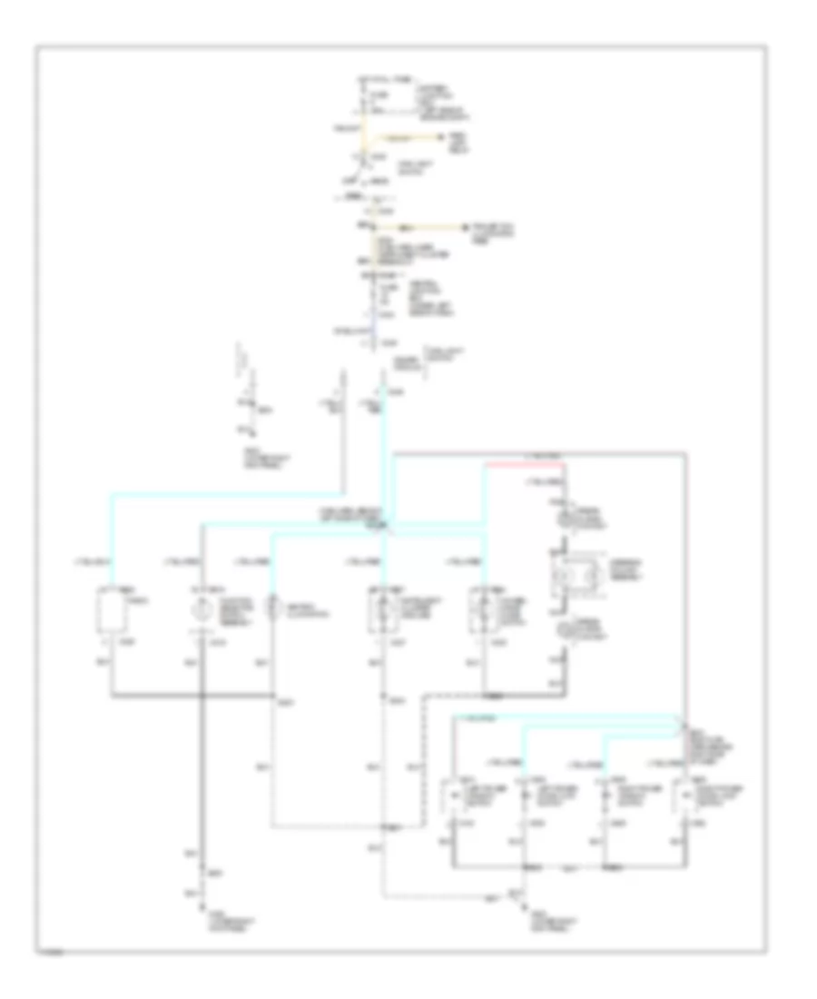
INTERIOR LIGHTS Courtesy Lamps Wiring Diagram for Ford Pickup F350 Super Duty 1999 List of elements for Courtesy Lamps Wiring Diagram for Ford Pickup F350 Super Duty 1999: 43 g105 (rear of right fender apron) s240 (main harn, near ashtray illum breakout) (body main harn, behind right side of dash) s239 Battery saver input Battery saver relay C239 C242 C243 C245 C246 C267 C306 C307 Central junction box (under left side of dash) Door ajar input Engine compartment lamp Fuse 15a G203 (lower right kick panel) Generic electronic module Glove compartment lamp Hot at all times Interior lamp Interior lamp relay Interior lamp relay input Interior lamp switch Interior/ map lamp Left cargo lamp Left door ajar switch Left door courtesy lamp Main light switch Map lamps Map lamps with xl & xlt only) Off Right cargo lamp Right door ajar switch Right door courtesy lamp S102 S203 S204 S300 (right seat belt retractor switch harn, near interior lamp breakout) S501 S600 S911 Instrument Illumination Wiring Diagram for Ford Pickup F350 Super Duty 1999 List of elements for Instrument Illumination Wiring Diagram for Ford Pickup F350 Super Duty 1999: 46 (main harn, behind left side of dash) s242 4wheel drive mode switch Airbag sliding contact Ashtray illumination Battery junction box (left side of engine compt) C219 C225 C230 C237 C242 C243 C245 C246 C508 C510 C608 C609 Central junction box (under left side of dash) Dimmer module Function selector switch assembly Fuse 15a Fuse 5a G203 (lower right kick panel) Head Hot at all times Instrument cluster (6 bulbs) Left power door lock switch Left power window switch Main light switch Nca Off Park Park lamp relay Radio Right power door lock switch Right power window switch S200 S201 S202 S203 S204 S224 (main harn, near instrument cluster breakout) S500 S600 Steering column assembly Trailer tow illumination feed
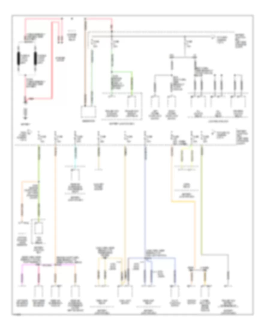
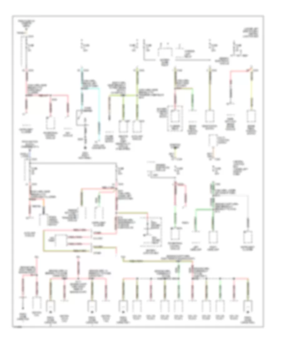
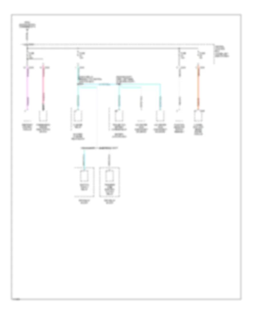
POWER DISTRIBUTION Power Distribution Wiring Diagram (1 of 4) for Ford Pickup F350 Super Duty 1999 List of elements for Power Distribution Wiring Diagram (1 of 4) for Ford Pickup F350 Super Duty 1999: 58 (body harn, near breakout to rap module) s216 (cable assembly harness, near battery) red s1001 (engine compt harn, near breakout to speed control servo) s152 (main harn, near breakout to main light switch) s212 (main harn, near breakout to passenger's air bag) s241 (rabs) (4wabs) 4 wheel abs 4 wheel anti-lock brake system module All lock relay All unlock relay Auxiliary power socket Battery Battery junction box Battery junction box (left side of engine compt) C142 C147 C277 Daytime running lamps resistor Driver's unlock relay Fog lamp relay From a fuse 8 (diagram 1 of 4) Fuse 15a Fuse 20a Fuse 20a 50a Fuse 25a Fuse 30a Fuse 50a Generator Headlamp relay Horn relay Ignition switch Left power door lock switch Left rear air spring solenoid Lock relay block Main light switch Multi- function switch Park lamp relay Rear abs Rear air suspension compressor motor/ vent solenoid Rear air suspension compressor relay Rear air suspension module Red Right power door lock switch Right rear air spring solenoid S1002 (cable assembly harness, near battery) S108 (engine compt harn, in breakout to bjb) S109 (engine compt harn left side of engine compt) S216 (body harn, near breakout to rap module) Starter motor Starter motor relay To fuse 102 (diagram 2 of 4) To fuse 9 (diagram 1 of 4) Trailer tow backup lamp relay Trailer tow battery charge relay Trailer tow running lamp relay W/ rap W/o rap With auto lamps Power Distribution Wiring Diagram (2 of 4) for Ford Pickup F350 Super Duty 1999 List of elements for Power Distribution Wiring Diagram (2 of 4) for Ford Pickup F350 Super Duty 1999: 71 (diagram 3 of 4) (engine compt harn, left rear of engine compt) s112 (engine compt harn, near breakout to bjb) s113 (main harn, in breakout to fuse relay panel) s265 (main harn, near breakout to instrument cluster) s222 (main harn, near breakout to instrument cluster) s223 (main harn, near breakout to rabs module) s217 A/t Acc Acc delay relay Battery junction box Battery junction box (left side of engine compt) Blend door actuator Blower relay Blower/ flasher relay block C222 C242 C243 C256 C267 C277 Central junction box Central junction box (under left side of dash) Digital trans- mission range sensor Electronic shift From b fuse 101 (diagram 1 of 4) Fuel pump relay Function selector switch assembly Fuse 15a Fuse 20a Fuse 20a (rabs) Fuse 30a Fuse 40a Fuse 50a Fuse 5a Generic electronic module Ignition switch Instrument cluster Lock M/t Manual shift Nca Off Pcm power relay Power seat control switch Radio Rear air suspension module Rear wheel anti-lock brakes system module Red Remote anti-theft personality module Reversing lamp switch Rpo relay block Run S214 (main harn, near steering wheel rotation sensor) S215 (main harn, in breakout to ignition switch) Shift lock actuator Shift on the fly relay Speed control servo Start Starting system To fuse 2 To fuse 22 (diagram 4 of 4) To fuse 29 Trailer adapter (electronic brake control) Transfer case electric clutch relay Transfer case shift module Washer pump relay Windshield wiper motor Wiper hi/lo relay Wiper run/park relay Wot relay Power Distribution Wiring Diagram (3 of 4) for Ford Pickup F350 Super Duty 1999 List of elements for Power Distribution Wiring Diagram (3 of 4) for Ford Pickup F350 Super Duty 1999: 84 (body harn, near breakout to park brake switch) (w/ rap only) s220 (engine compt harn, near breakout breakout to g108) s114 (engine compt harn, right rear of engine compt) s117 (engine harn, in breakout to fuel injector 3) (engine harn, in breakout to noise capacitor 1) s118 (engine harn, in breakout to noise capacitor 2) s119 (engine harn, right rear of engine compt) s117 (main harn, behind left side of dash) s289 (main harn, near breakout to instrument cluster) s225 (main harn, near breakout to instrument cluster) s236 (main harn, near breakout to transfer case relay) s219 (main harn, right side of dash) s221 (main harn, under left side of dash) s218 (under left side of dash) central junction box 4.2l 4.6l 5.4l 5.4l ngv Autolamp module Battery junction box Battery saver relay Blower/ flasher relay block Brake pedal position switch C174 C216 C242 C243 C257 C267 Central junction box (under left side of dash) Cigar lighter Coil on plug 1 Coil on plug 2 Coil on plug 3 Coil on plug 4 Coil on plug 5 Coil on plug 6 Coil on plug 7 Coil on plug 8 Data link connector Deactivation switch Flasher relay From fuse 103 (diagram 2 of 4) From ignition switch (diagram 2 of 4) Fuse 15a Fuse 20a Fuse 30a Fuse 5a G203 (right kick panel) Generic electronic module Ignition coil Ignition coils 1 & 2 Ignition coils 3 & 4 Injector 7) s162 Instrument cluster Interior lamp relay Left headlamp Multi- function switch Nca Ngv module Ngv timer Other Passive anti-theft system transceiver module Pcm power diode Pcm power relay Power mirror switch Powertrain control module Radio Radio noise capacitor Radio noise capacitor 1 Radio noise capacitor 2 Rear anti-lock brake system module Red Red/ Remote anti- theft personality module (if equipped) Right headlamp S116 (engine harn, near breakout to engine fuse module) S117 (engine compt harn, right rear of engine compt) S158 S161 S205 S237 (main harn, under left side of dash) Starting system Trans- mission control switch Power Distribution Wiring Diagram (4 of 4) for Ford Pickup F350 Super Duty 1999 List of elements for Power Distribution Wiring Diagram (4 of 4) for Ford Pickup F350 Super Duty 1999: 26 (engine compt harn, left rear of engine compt) s120 (main harn, in breakout to central junction box) s228 4 wheel anti-lock brake system module 4x2 center axle disconnect solenoid 4x4 center axle disconnect solenoid Battery junction box Blower/ flasher relay block C146 C243 C243 tan/red Central junction box (under left side of dash) Electronic shift Flasher relay From ignition switch (diagram 2 of 4) Function selector switch assembly Fuse 10a Fuse 5a Manual shift Nca Passenger's air bag deactivation switch Restraint control module Rpo relay block Shift on the fly relay Tan/red Trailer tow battery charge relay Transfer case electric clutch relay
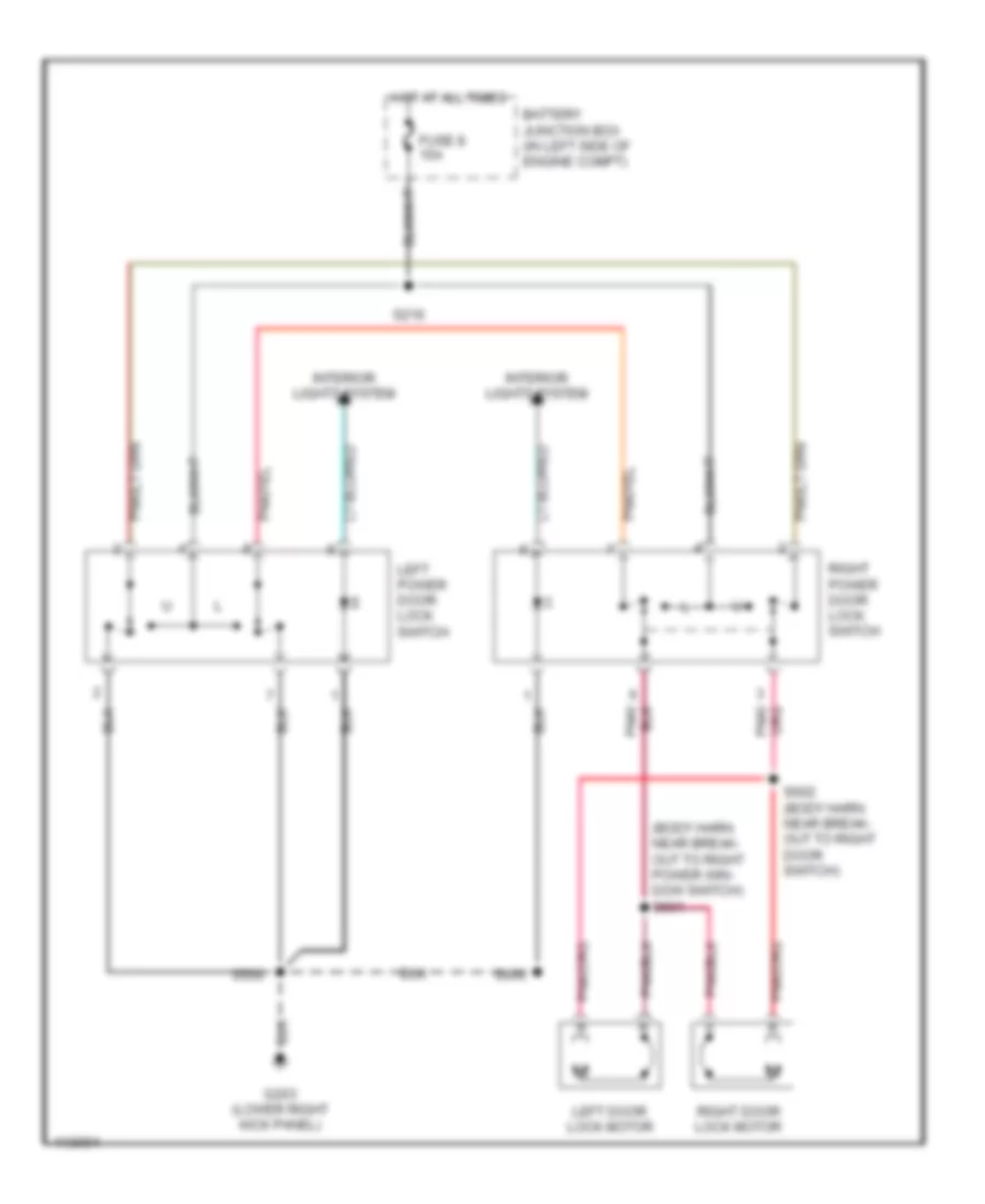
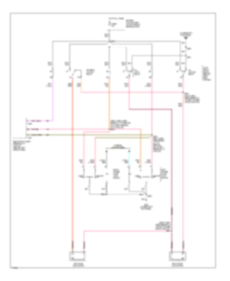
POWER DOOR LOCKS Door Lock Wiring Diagram for Ford Pickup F350 Super Duty 1999 List of elements for Door Lock Wiring Diagram for Ford Pickup F350 Super Duty 1999: 14 (body harn near break- out to right power win- dow switch) s601 Battery junction box (in left side of engine compt) Fuse 8 15a G203 (lower right kick panel) Hot at all times Interior lights system Left door lock motor Left power door lock switch Right door lock motor Right power door lock switch S216 S500 S600 S602 (body harn near break- out to right door switch) Keyless Entry Wiring Diagram for Ford Pickup F350 Super Duty 1999 List of elements for Keyless Entry Wiring Diagram for Ford Pickup F350 Super Duty 1999: 28 (body harn, near breakout to remote anti-theft person- ality module) s234 (body harn, near breakout to right power window switch) s601 (lower right kick panel) g203 87a All lock relay All unlock relay Battery junction box (in left side of engine compt) C256 C257 Driver's unlock relay Fuse 8 15a G203 (lower right kick panel) Hot at all times Interior lights system Left door lock motor Left power door lock switch Lock Lock relay block (behind right side of dash) Remote anti-theft personality module (behind left side of dash) Right door lock motor Right power door lock switch S216 S235 (body harn, near break- out to remote anti-theft personality module) S500 S501 S600 S602 (body harn, near breakout to right power window switch) Unlock
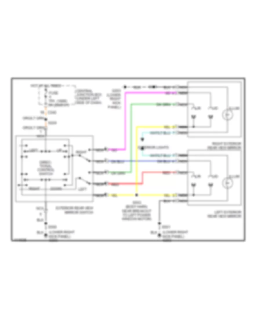
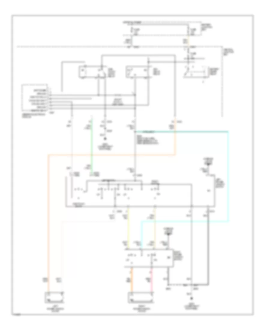
POWER MIRRORS Power Mirror Wiring Diagram for Ford Pickup F350 Super Duty 1999 List of elements for Power Mirror Wiring Diagram for Ford Pickup F350 Super Duty 1999: 26 (1999) (2000-01) (lower right kick panel) g203 C242 Central junction box (under left side of dash) Direc- tional control switch Down Exterior lights Exterior rear view mirror switch Fuse 15a 5a G203 (lower right kick panel) Hot at all times Illum L/r Left Left exterior rear view mirror Nca Red Right Right exterior rear view mirror S220 S500 S501 S503 (body harn, near breakout to left power window motor) S600 U/d
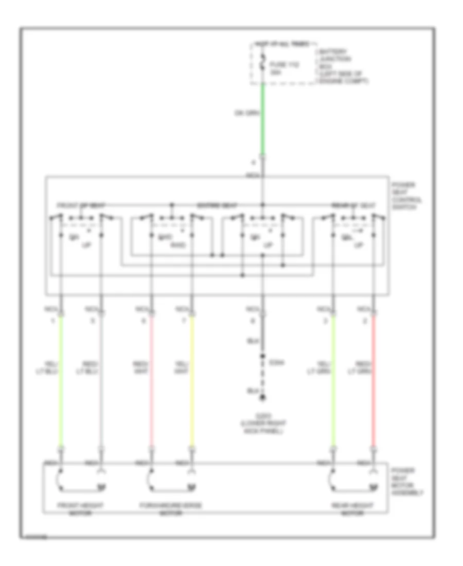
POWER SEATS Power Seat Wiring Diagrams for Ford Pickup F350 Super Duty 1999 List of elements for Power Seat Wiring Diagrams for Ford Pickup F350 Super Duty 1999: 16 Battery junction box (left side of engine compt) Entire seat Forward/reverse motor Front height motor Front of seat Fuse 112 30a Fwd G203 (lower right kick panel) Hot at all times Nca Power seat control switch Power seat motor assembly Rear height motor Rear of seat Rwd S304
POWER WINDOWS Power Window Wiring Diagram for Ford Pickup F350 Super Duty 1999 List of elements for Power Window Wiring Diagram for Ford Pickup F350 Super Duty 1999: 37 (2000) (1999) 87a Acc delay relay Batt saver Battery junction box Battery saver relay C242 C243 C267 C509 C510 Central junction box Down sw input Fuse 15a Fuse 30a Fuse 50a G203 (lower right kick panel) Generic electronic module Ground Hot at all times Interior lights system Left power window motor Left power window switch Left switch One tch dn hi One tch dn lo One touch down One touch down relay Otd sw input Right power window motor Right power window switch Right switch S205 S248 (body main harn, near breakout to park brake switch) S500 S600 Shunt (0.015 +/- 0.001 ohm)
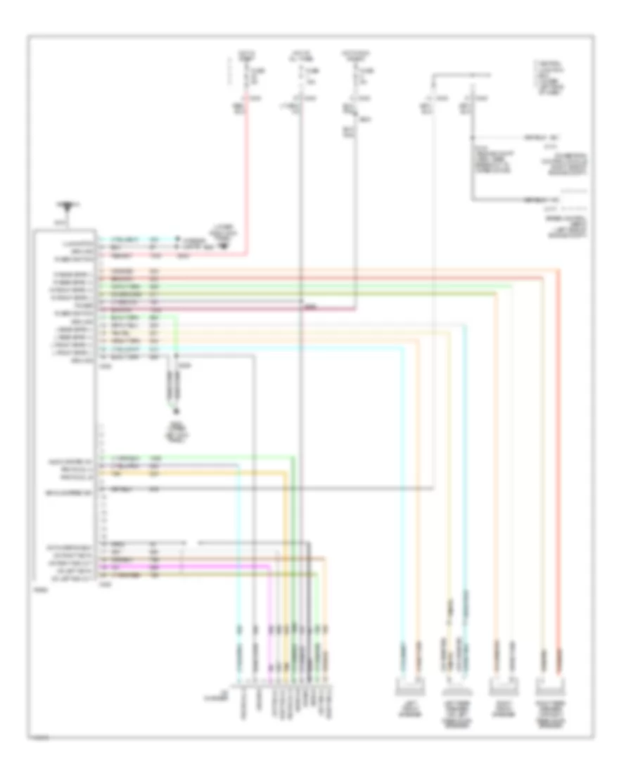
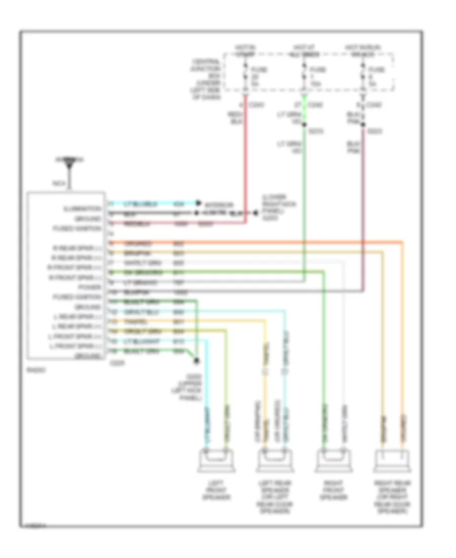
RADIO Radio Wiring Diagrams, with CD Changer for Ford Pickup F350 Super Duty 1999 List of elements for Radio Wiring Diagrams, with CD Changer for Ford Pickup F350 Super Duty 1999: 59 (lower right kick panel) g203 Antenna Audio on Audio system on Bare C174 C177 C225 C228 C242 C243 Cd changer Cd left sig in Cd left sig out Cd player shield Cd right sig in Cd right sig out Central junction box (under left side of dash) Fuse 15a Fuse 5a Fused ignition G202 (upper left kick panel) Ground Hot at all times Hot in run or acc Hot in start Ilumination Interior lights L front spkr (+) L front spkr (-) L rear spkr (+) L rear spkr (-) Left front speaker Left rear speaker (or left rear door speaker) Left sig (+) Left sig (-) Nca Power Powertrain control module (right side of engine compt) Protocol a Protocol b R front spkr (+) R front spkr (-) R rear spkr (+) R rear spkr (-) Radio Right front speaker Right rear speaker (or right rear door speaker) Right sig (+) Right sig (-) S143 (engine compt harn, near breakout to wiper motor) S203 S209 S223 S233 Shield Speed control servo (left side of engine compt) Tan Vehicle speed sig Radio Wiring Diagrams, without CD Changer for Ford Pickup F350 Super Duty 1999 List of elements for Radio Wiring Diagrams, without CD Changer for Ford Pickup F350 Super Duty 1999: 34 (lower right kick panel) g203 Antenna C225 C242 C243 Central junction box (under left side of dash) Fuse 15a Fuse 5a Fused ignition G202 (upper left kick panel) Ground Hot at all times Hot in run or acc Hot in start Ilumination Interior lights L front spkr (+) L front spkr (-) L rear spkr (+) L rear spkr (-) Left front speaker Left rear speaker (or left rear door speaker) Nca Power R front spkr (+) R front spkr (-) R rear spkr (+) R rear spkr (-) Radio Right front speaker Right rear speaker (or right rear door speaker) S203 S223 S233
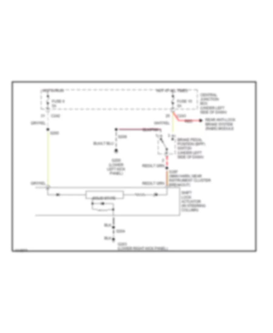
SHIFT INTERLOCKS Shift Interlock Wiring Diagram for Ford Pickup F350 Super Duty 1999 List of elements for Shift Interlock Wiring Diagram for Ford Pickup F350 Super Duty 1999: 18 Brake pedal position (bpp) switch (under left side of dash) C242 C243 Central junction box (under left side of dash) Fuse 15 5a Fuse 6 5a G200 (lower left kick panel) G203 (lower right kick panel) Hot at all times Hot in run Rear anti-lock brake system (rabs) module Red S204 S208 S265 S297 (main harn, near instrument cluster breakout) Shift lock actuator (in steering column) Solid state
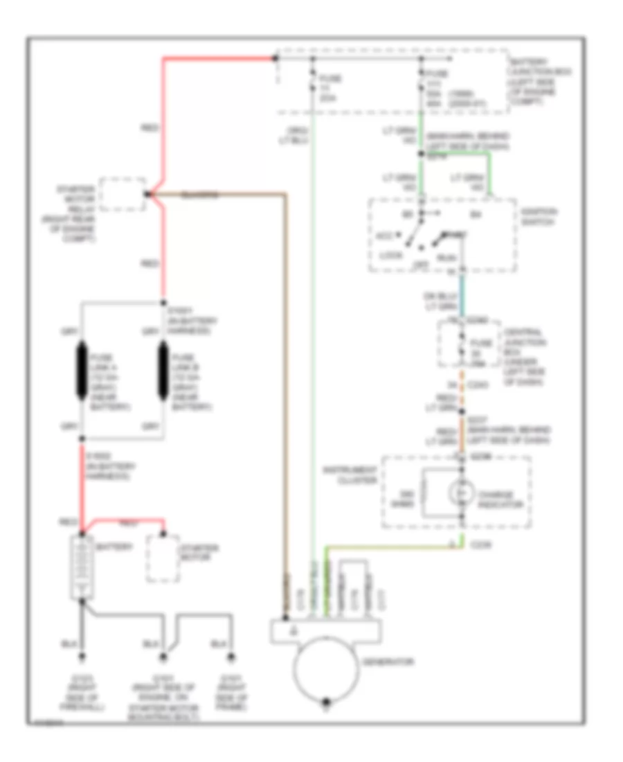
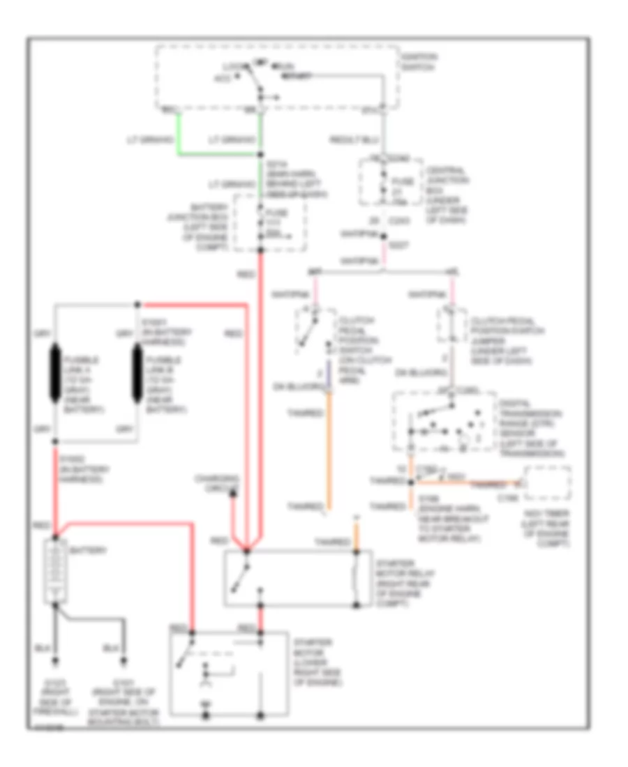
STARTING/CHARGING Charging Wiring Diagram for Ford Pickup F350 Super Duty 1999 List of elements for Charging Wiring Diagram for Ford Pickup F350 Super Duty 1999: 33 (1999) (2000-01) (main harn, behind left side of dash) s214 0hms Acc Battery Battery junction box (left side of engine compt) C176 C177 C178 C236 C243 Central junction box (under left side of dash) Charge indicator Fuse 2oa Fuse 30a Fuse 50a 40a Fuse link a (12 ga- gray) (near battery) Fuse link b (12 ga- gray) (near battery) G101 (right side of engine, on starter motor mounting bolt) G101 (right side of frame) G123 (right side of firewall) Generator Ignition switch Instrument cluster Left side of dash) Lock Off Red Run S1002 (in battery harness) Start Starter motor Starter motor relay (right rear of engine compt) Starting Wiring Diagram for Ford Pickup F350 Super Duty 1999 List of elements for Starting Wiring Diagram for Ford Pickup F350 Super Duty 1999: 36 A/t Acc Battery Battery junction box (left side of engine compt) C182 C196 C243 Central junction box (under left side of dash) Charging circuit Clutch pedal position switch (on clutch pedal arm) Clutch pedal position switch jumper (under left side of dash) Digital transmission range (dtr) sensor (left side of transmission) Fuse 15a Fuse 50a Fusible link a (12 ga- gray) (near battery) Fusible link b (12 ga- gray) (near battery) G101 (right side of engine, on starter motor mounting bolt) G123 (right side of firewall) Harness) Ignition switch Lock M/t Ngv Ngv timer (left rear of engine compt) Off Red Run S1002 (in battery harness) S198 (engine harn, near breakout to starter motor relay) S214 (main harn, behind left side of dash) S227 Sta Start Starter motor (lower right side of engine) Starter motor relay (right rear of engine compt) Tan/red
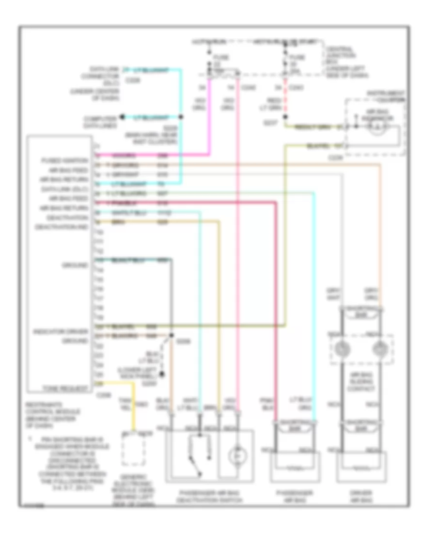
SUPPLEMENTAL RESTRAINTS Supplemental Restraint Wiring Diagram for Ford Pickup F350 Super Duty 1999 List of elements for Supplemental Restraint Wiring Diagram for Ford Pickup F350 Super Duty 1999: 38 (lower left kick panel) g200 (under center of dash) Air bag feed Air bag indicator Air bag return Air bag sliding contact C208 C236 C239 C242 C243 Central junction box (under left side of dash) Computer data lines Connector c228 (dlc) Data link Data link (dlc) Deactivation Deactivation ind Driver air bag Fuse 10a Fuse 30a Fused ignition Generic electronic module (gem) (behind left side of dash) Ground Hot in run Hot in run or start Indicator driver Instrument cluster Nca Passenger air bag Passenger air bag deactivation switch Pin shorting bar is engaged when module connector is disconnected (shorting bar is connected between the following pins: 3-4, 6-7, 20-21) Restraints control module (behind center of dash) S208 S229 (main harn, near inst cluster) S237 Shorting bar Tone request
TRANSMISSION
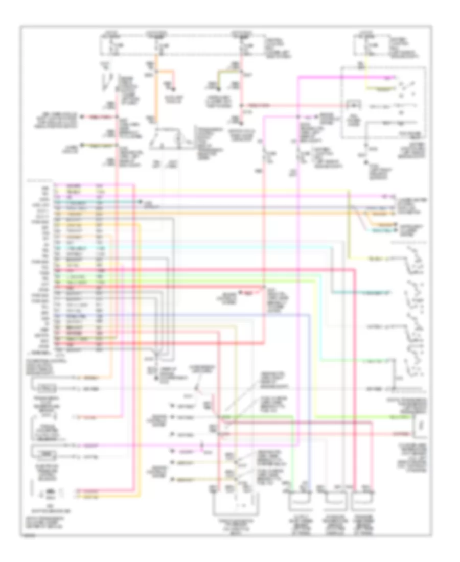
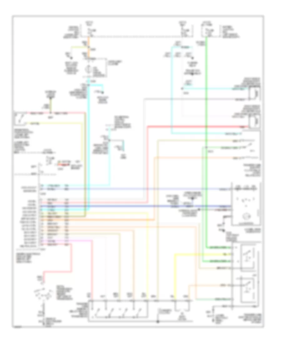
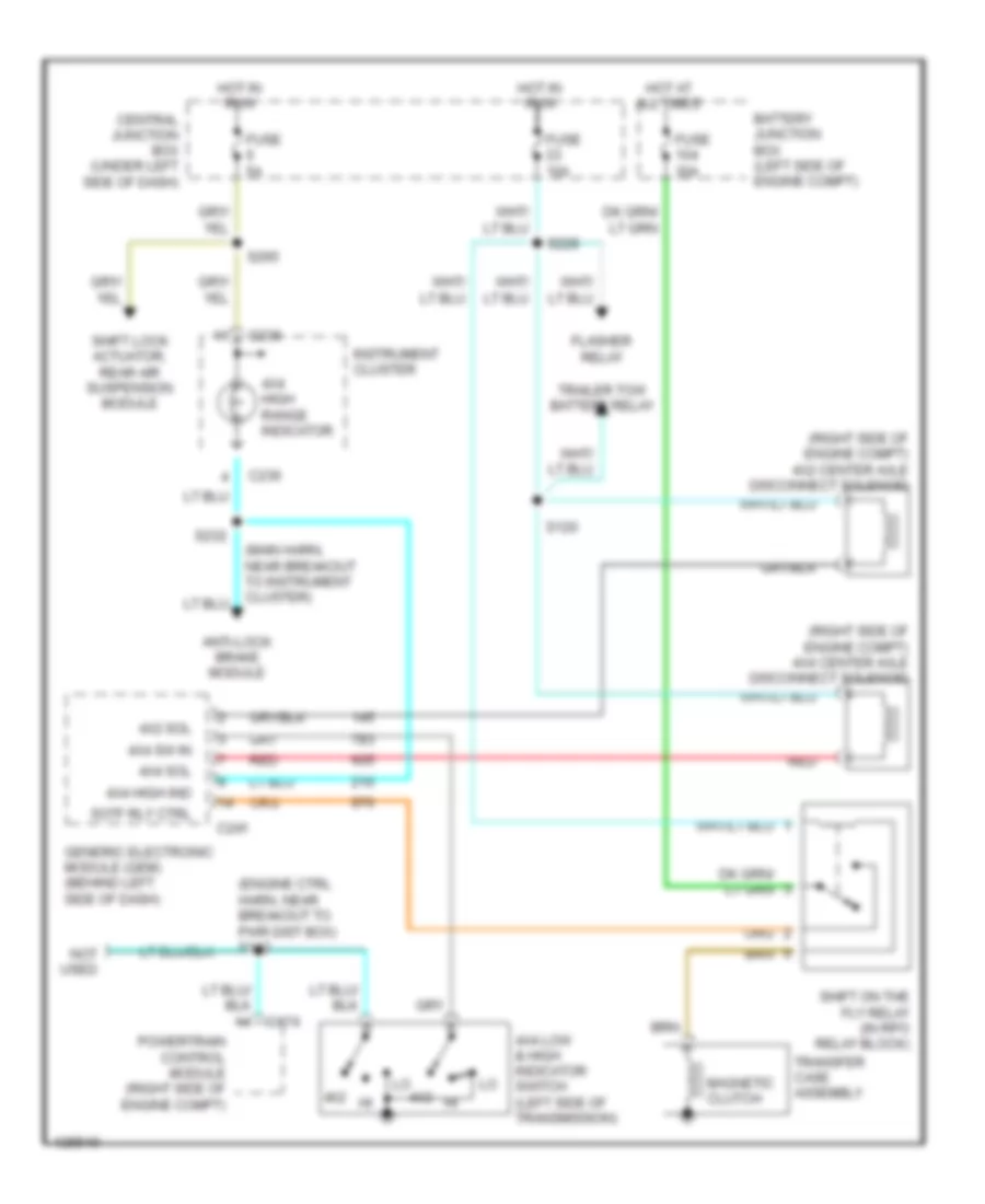
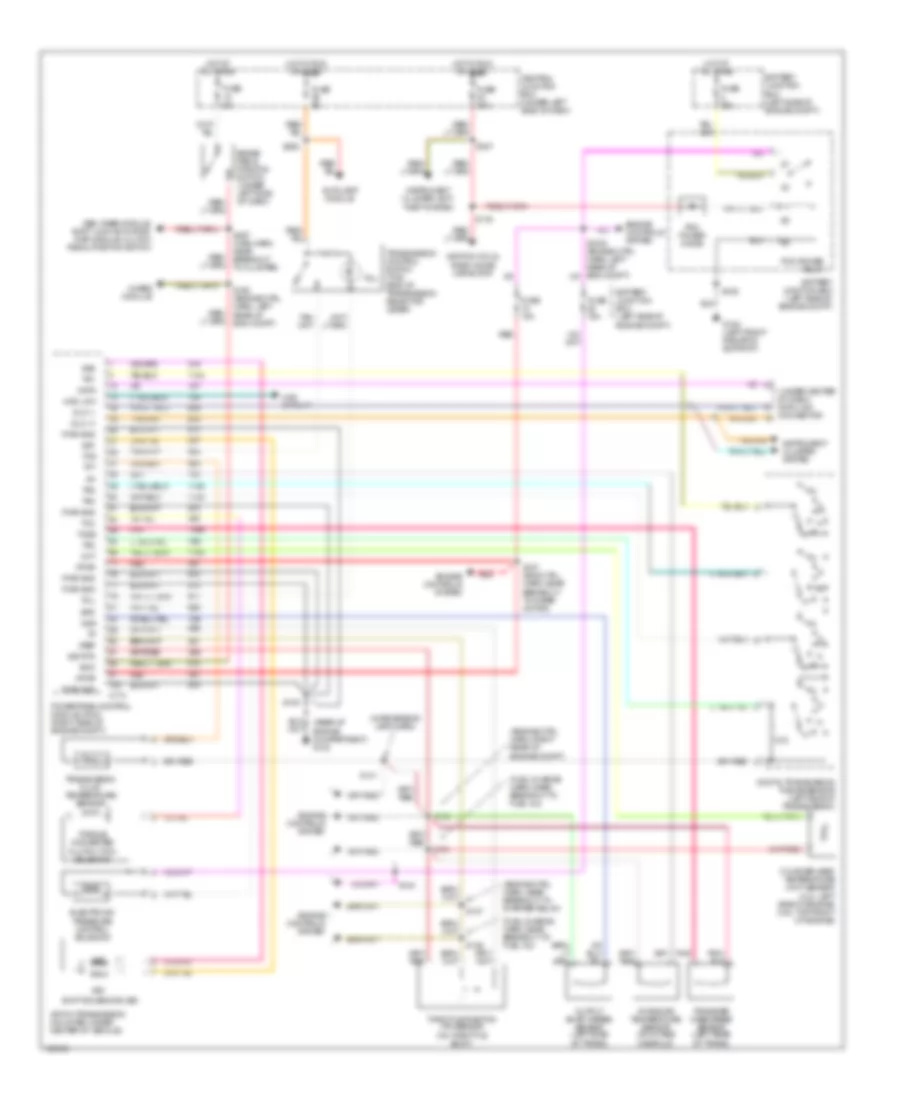
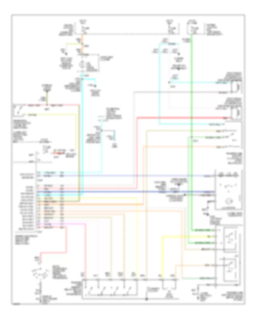
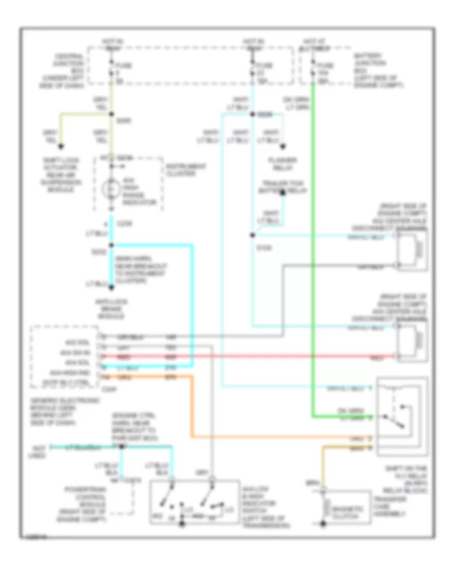
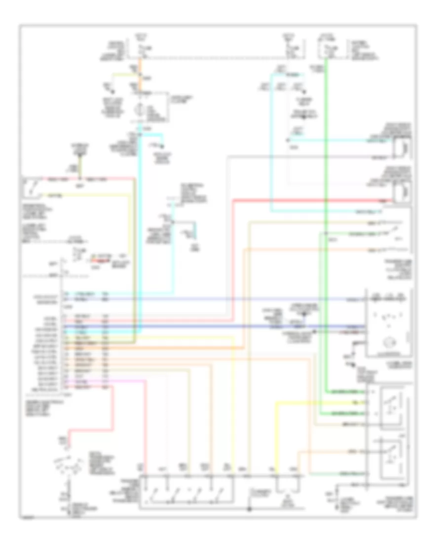
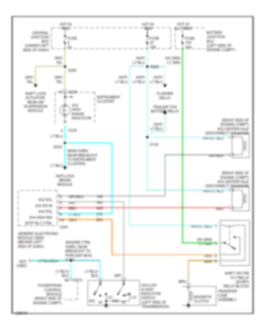
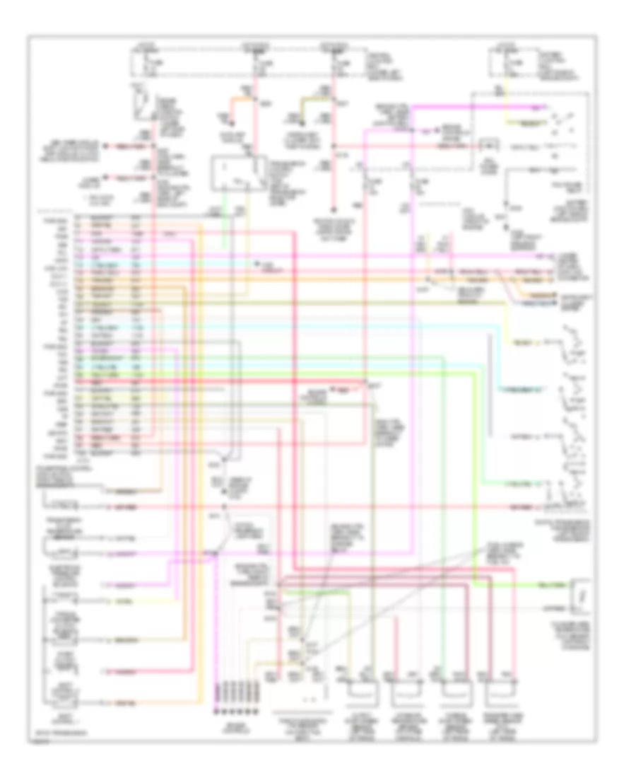
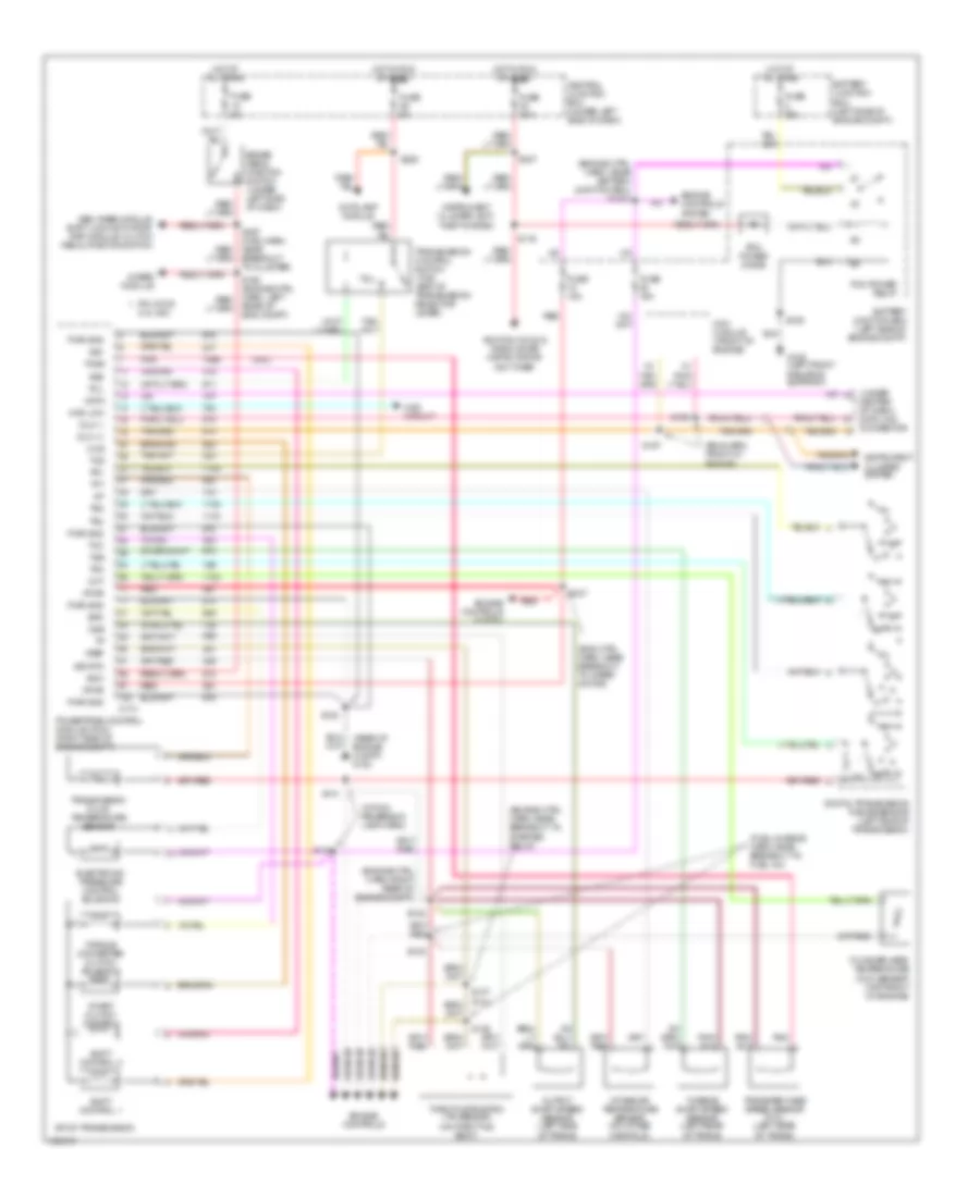
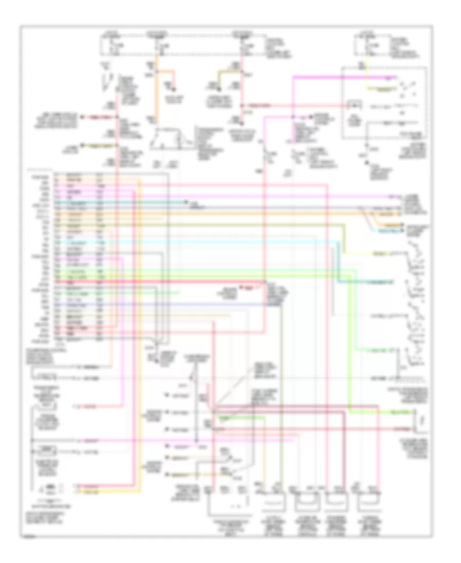
4.2L 4.2L, A/T Wiring Diagram, 4R70W for Ford Pickup F350 Super Duty 1999 List of elements for 4.2L, A/T Wiring Diagram, 4R70W for Ford Pickup F350 Super Duty 1999: 80 (engine ctrl harn, near breakout to starter relay) (engine ctrl harn, right rear of engine compt) (fuel charge harn, near breakout to fuel inj) (in reversing lamp harn) (rear of engine compartment) g123 (under center of dash) data link connector 4r70w transmission (mounted under center of vehicle) 4wabs module 4wd circuit 4wd low Autolamp module Battery junction box (left side of engine compt) Boo Brake pedal position switch (under left side of dash) C174 Central junction box (under left side of dash) Cht Cylinder head temperature (cht) sensor (4.2l: left side of engine) (4.6l: top front of engine) Data Digital transmission range sensor (left side of transmission) Dlc (+) Dlc (-) Electronic pressure control solenoid Engine controls system Epc Fuse 15a Fuse 30a Fuse 5a G108 (left front radiator support) Gem, rabs module, shift lock actuator, rap module, clutch pedal position switch Hot at all times Hot in run or start Iat Ignition coils, radio noise capacitor Instrument cluster system Instrument cluster, anti- theft system Intake air temperature sensor (on intake manifold) Oss Output shaft speed sensor (left side of trans) Pcm power diode Pcm power relay Pnk Powertrain control module (pcm) (right side of engine compt) Pwr gnd R p Red S100 S106 S116 S127 (eng ctrl harn, near breakout to wiper motor) S135 S136 S137 S138 S140 S141 S160 (engine ctrl harn, left rear of eng compt) S225 S237 S297 (main harn, near breakout to cluster) Shift solenoids (ss) Sig rtn Ss1 Ss2 Tcc Tcil Tcs Tcss Tft Throttle position (tp) sensor (on throttle body) Torque converter clutch (tcc) solenoid Tr1 Tr2 Tr3 Tr4 Transfer case speed sensor (left rear of trans) Transmission control switch (tcs) (end of transmission selector lever) Transmission fluid temperature sensor Vpwr Vref 4WD Wiring Diagram, Electronic for Ford Pickup F350 Super Duty 1999 List of elements for 4WD Wiring Diagram, Electronic for Ford Pickup F350 Super Duty 1999: 75 (lower right kick panel) g203 (main harn, near breakout to gem) (right side of engine compt) 4x2 center axle disconnect solenoid (right side of engine compt) 4x4 center axle disconnect solenoid (under left side of dash) central junction box 1.1k ohms 3.9k ohms 4 wheel drive mode switch 4wd low out 4wd output 4x2 sol 4x4 high ind 4x4 high range indicator 4x4 mode sw 4x4 sol Anti-lock brake module Anti-lock brakes Apron) g105 Batt Battery junction box (left side of engine compt) Bpp sw input Brake pedal position switch (under left side of dash) C174 C236 C239 C241 C243 Central junction box (under left side of dash) Digital transmission range (dtr) sensor (left side of transmission) Exterior lights system Flasher relay Fuse 10a Fuse 30a Fuse 5a G108 (top front radiator support) Generic electronic module (gem) (behind left side of dash) H2l H2l rly ctrl Hot at all times Hot in run Illumination Instrument cluster Interior lights (instrument illumination) L2h L2h rly ctrl Magnetic clutch Neutral sw in Not used Ohms Powertrain control module (right side of engine compt) Red S102 S120 S142 (engine ctrl harn, near breakout to pwr dist box) S201 S202 S213 S228 S232 (main harn, near breakout to instrument cluster) S238 S265 S297 Shift lock actuator, rear air suspension module Shift motor Sig return Sw a input Sw b input Sw c input Sw d input Tcec rly ctrl Trailer tow battery relay Transfer case assembly (below vehicle, behind transmission) Transfer case electric clutch relay (in rpo relay block) Transfer case shift relay module (behind center of dash) Wiper/washer (multi-function switch) 4WD Wiring Diagram, Mechanical for Ford Pickup F350 Super Duty 1999 List of elements for 4WD Wiring Diagram, Mechanical for Ford Pickup F350 Super Duty 1999: 38 (engine ctrl harn, near breakout to pwr dist box) s142 (main harn, near breakout to instrument cluster) (right side of engine compt) 4x2 center axle disconnect solenoid (right side of engine compt) 4x4 center axle disconnect solenoid 4x2 4x2 sol 4x4 high ind 4x4 high range indicator 4x4 low & high indicator switch (left side of transmission) 4x4 sol 4x4 sw in Anti-lock brake module Battery junction box (left side of engine compt) C174 C236 C241 Central junction box (under left side of dash) Flasher relay Fuse 10a Fuse 30a Fuse 5a Generic electronic module (gem) (behind left side of dash) Hot at all times Hot in run Instrument cluster Magnetic clutch Not used Powertrain control module (right side of engine compt) Red S120 S228 S232 S265 Shift lock actuator, rear air suspension module Shift on the fly relay (in rpo relay block) Sotf rly ctrl Trailer tow battery relay Transfer case assembly
4.6L 4.6L, A/T Wiring Diagram, 4R70W for Ford Pickup F350 Super Duty 1999 List of elements for 4.6L, A/T Wiring Diagram, 4R70W for Ford Pickup F350 Super Duty 1999: 80 (engine ctrl harn, near breakout to starter relay) (engine ctrl harn, right rear of engine compt) (fuel charge harn, near breakout to fuel inj) (in reversing lamp harn) (rear of engine compartment) g123 (under center of dash) data link connector 4r70w transmission (mounted under center of vehicle) 4wabs module 4wd circuit 4wd low Autolamp module Battery junction box (left side of engine compt) Boo Brake pedal position switch (under left side of dash) C174 Central junction box (under left side of dash) Cht Cylinder head temperature (cht) sensor (4.2l: left side of engine) (4.6l: top front of engine) Data Digital transmission range sensor (left side of transmission) Dlc (+) Dlc (-) Electronic pressure control solenoid Engine controls system Epc Fuse 15a Fuse 30a Fuse 5a G108 (left front radiator support) Gem, rabs module, shift lock actuator, rap module, clutch pedal position switch Hot at all times Hot in run or start Iat Ignition coils, radio noise capacitor Instrument cluster system Instrument cluster, anti- theft system Intake air temperature sensor (on intake manifold) Oss Output shaft speed sensor (left side of trans) Pcm power diode Pcm power relay Pnk Powertrain control module (pcm) (right side of engine compt) Pwr gnd R p Red S100 S106 S116 S127 (eng ctrl harn, near breakout to wiper motor) S135 S136 S137 S138 S140 S141 S160 (engine ctrl harn, left rear of eng compt) S225 S237 S297 (main harn, near breakout to cluster) Shift solenoids (ss) Sig rtn Ss1 Ss2 Tcc Tcil Tcs Tcss Tft Throttle position (tp) sensor (on throttle body) Torque converter clutch (tcc) solenoid Tr1 Tr2 Tr3 Tr4 Transfer case speed sensor (left rear of trans) Transmission control switch (tcs) (end of transmission selector lever) Transmission fluid temperature sensor Vpwr Vref 4WD Wiring Diagram, Electronic for Ford Pickup F350 Super Duty 1999 List of elements for 4WD Wiring Diagram, Electronic for Ford Pickup F350 Super Duty 1999: 75 (lower right kick panel) g203 (main harn, near breakout to gem) (right side of engine compt) 4x2 center axle disconnect solenoid (right side of engine compt) 4x4 center axle disconnect solenoid (under left side of dash) central junction box 1.1k ohms 3.9k ohms 4 wheel drive mode switch 4wd low out 4wd output 4x2 sol 4x4 high ind 4x4 high range indicator 4x4 mode sw 4x4 sol Anti-lock brake module Anti-lock brakes Apron) g105 Batt Battery junction box (left side of engine compt) Bpp sw input Brake pedal position switch (under left side of dash) C174 C236 C239 C241 C243 Central junction box (under left side of dash) Digital transmission range (dtr) sensor (left side of transmission) Exterior lights system Flasher relay Fuse 10a Fuse 30a Fuse 5a G108 (top front radiator support) Generic electronic module (gem) (behind left side of dash) H2l H2l rly ctrl Hot at all times Hot in run Illumination Instrument cluster Interior lights (instrument illumination) L2h L2h rly ctrl Magnetic clutch Neutral sw in Not used Ohms Powertrain control module (right side of engine compt) Red S102 S120 S142 (engine ctrl harn, near breakout to pwr dist box) S201 S202 S213 S228 S232 (main harn, near breakout to instrument cluster) S238 S265 S297 Shift lock actuator, rear air suspension module Shift motor Sig return Sw a input Sw b input Sw c input Sw d input Tcec rly ctrl Trailer tow battery relay Transfer case assembly (below vehicle, behind transmission) Transfer case electric clutch relay (in rpo relay block) Transfer case shift relay module (behind center of dash) Wiper/washer (multi-function switch) 4WD Wiring Diagram, Mechanical for Ford Pickup F350 Super Duty 1999 List of elements for 4WD Wiring Diagram, Mechanical for Ford Pickup F350 Super Duty 1999: 38 (engine ctrl harn, near breakout to pwr dist box) s142 (main harn, near breakout to instrument cluster) (right side of engine compt) 4x2 center axle disconnect solenoid (right side of engine compt) 4x4 center axle disconnect solenoid 4x2 4x2 sol 4x4 high ind 4x4 high range indicator 4x4 low & high indicator switch (left side of transmission) 4x4 sol 4x4 sw in Anti-lock brake module Battery junction box (left side of engine compt) C174 C236 C241 Central junction box (under left side of dash) Flasher relay Fuse 10a Fuse 30a Fuse 5a Generic electronic module (gem) (behind left side of dash) Hot at all times Hot in run Instrument cluster Magnetic clutch Not used Powertrain control module (right side of engine compt) Red S120 S228 S232 S265 Shift lock actuator, rear air suspension module Shift on the fly relay (in rpo relay block) Sotf rly ctrl Trailer tow battery relay Transfer case assembly
5.4L 4WD Wiring Diagram, Electronic for Ford Pickup F350 Super Duty 1999 List of elements for 4WD Wiring Diagram, Electronic for Ford Pickup F350 Super Duty 1999: 75 (lower right kick panel) g203 (main harn, near breakout to gem) (right side of engine compt) 4x2 center axle disconnect solenoid (right side of engine compt) 4x4 center axle disconnect solenoid (under left side of dash) central junction box 1.1k ohms 3.9k ohms 4 wheel drive mode switch 4wd low out 4wd output 4x2 sol 4x4 high ind 4x4 high range indicator 4x4 mode sw 4x4 sol Anti-lock brake module Anti-lock brakes Apron) g105 Batt Battery junction box (left side of engine compt) Bpp sw input Brake pedal position switch (under left side of dash) C174 C236 C239 C241 C243 Central junction box (under left side of dash) Digital transmission range (dtr) sensor (left side of transmission) Exterior lights system Flasher relay Fuse 10a Fuse 30a Fuse 5a G108 (top front radiator support) Generic electronic module (gem) (behind left side of dash) H2l H2l rly ctrl Hot at all times Hot in run Illumination Instrument cluster Interior lights (instrument illumination) L2h L2h rly ctrl Magnetic clutch Neutral sw in Not used Ohms Powertrain control module (right side of engine compt) Red S102 S120 S142 (engine ctrl harn, near breakout to pwr dist box) S201 S202 S213 S228 S232 (main harn, near breakout to instrument cluster) S238 S265 S297 Shift lock actuator, rear air suspension module Shift motor Sig return Sw a input Sw b input Sw c input Sw d input Tcec rly ctrl Trailer tow battery relay Transfer case assembly (below vehicle, behind transmission) Transfer case electric clutch relay (in rpo relay block) Transfer case shift relay module (behind center of dash) Wiper/washer (multi-function switch) 4WD Wiring Diagram, Mechanical for Ford Pickup F350 Super Duty 1999 List of elements for 4WD Wiring Diagram, Mechanical for Ford Pickup F350 Super Duty 1999: 38 (engine ctrl harn, near breakout to pwr dist box) s142 (main harn, near breakout to instrument cluster) (right side of engine compt) 4x2 center axle disconnect solenoid (right side of engine compt) 4x4 center axle disconnect solenoid 4x2 4x2 sol 4x4 high ind 4x4 high range indicator 4x4 low & high indicator switch (left side of transmission) 4x4 sol 4x4 sw in Anti-lock brake module Battery junction box (left side of engine compt) C174 C236 C241 Central junction box (under left side of dash) Flasher relay Fuse 10a Fuse 30a Fuse 5a Generic electronic module (gem) (behind left side of dash) Hot at all times Hot in run Instrument cluster Magnetic clutch Not used Powertrain control module (right side of engine compt) Red S120 S228 S232 S265 Shift lock actuator, rear air suspension module Shift on the fly relay (in rpo relay block) Sotf rly ctrl Trailer tow battery relay Transfer case assembly 5.4L CNG, A/T Wiring Diagram, 4R100 for Ford Pickup F350 Super Duty 1999 List of elements for 5.4L CNG, A/T Wiring Diagram, 4R100 for Ford Pickup F350 Super Duty 1999: 95 (5.4l) (eng ctrl harn, near breakout to wiper motor) (eng harn, front of engine) (engine ctrl harn, near battery junction box) s1003 (engine ctrl harn, near breakout to starter relay) (engine ctrl harn, right rear of engine compt) (fuel charge harn, near breakout to fuel inj) (rear of engine compt) g123 (under (within reversing lamp harn) 4r100 transmission 4wabs module 4wd circuit 4wd low Autolamp module Battery junction box (left side of engine compt) Boo Brake pedal position switch (under left side of dash) Breakout to cluster) C174 Ccs Center of dash) data link connector Central junction box (under left side of dash) Cht Coast clutch control Cylinder head temperature (cht) sensor (top front of engine) Data Digital transmission range sensor (left side of transmission) Dlc (+) Dlc (-) Electronic pressure control solenoid Engine controls Engine controls system Epc Fuse 15a Fuse 30a Fuse 5a G108 (left front radiator support) Gem, rabs module, shift lock actuator, rap module, clutch pedal position switch Hot at all times Hot in run or start Iat Ignition coils & radio noise capacitor or ngv timer Instrument cluster system Instrument cluster, anti- theft system Intake air temperature sensor (on intake manifold) Ngv module (front of engine) Oss Output shaft speed sensor (left side of trans) Pcm power diode Pcm power relay Pin 3 for 5.4l ngv Pnk Powertrain control module (pcm) (right side of engine compt) Pwr gnd R p Rear of eng compt) Red S100 S106 S116 S127 S135 S136 S137 (5.4l) S138 S140 S141 S156 S157 S225 S237 Shift control 1 Shift control 2 Sig rtn Ss1 Ss2 Tcc Tcil Tcs Tcss Tft Throttle position (tp) sensor (on throttle body) Torque converter clutch solenoid Tr1 Tr2 Tr3 Tr4 Transfer case speed sensor (5.4l) (left rear of trans) Transmission control switch (tcs) (end of transmission selector lever) Transmission fluid temperature sensor Tss Turbine shaft speed sensor (left rear of trans) Vpwr Vref 5.4L, A/T Wiring Diagram, 4R100 for Ford Pickup F350 Super Duty 1999 List of elements for 5.4L, A/T Wiring Diagram, 4R100 for Ford Pickup F350 Super Duty 1999: 95 (5.4l) (eng ctrl harn, near breakout to wiper motor) (eng harn, front of engine) (engine ctrl harn, near battery junction box) s1003 (engine ctrl harn, near breakout to starter relay) (engine ctrl harn, right rear of engine compt) (fuel charge harn, near breakout to fuel inj) (rear of engine compt) g123 (under (within reversing lamp harn) 4r100 transmission 4wabs module 4wd circuit 4wd low Autolamp module Battery junction box (left side of engine compt) Boo Brake pedal position switch (under left side of dash) Breakout to cluster) C174 Ccs Center of dash) data link connector Central junction box (under left side of dash) Cht Coast clutch control Cylinder head temperature (cht) sensor (top front of engine) Data Digital transmission range sensor (left side of transmission) Dlc (+) Dlc (-) Electronic pressure control solenoid Engine controls Engine controls system Epc Fuse 15a Fuse 30a Fuse 5a G108 (left front radiator support) Gem, rabs module, shift lock actuator, rap module, clutch pedal position switch Hot at all times Hot in run or start Iat Ignition coils & radio noise capacitor or ngv timer Instrument cluster system Instrument cluster, anti- theft system Intake air temperature sensor (on intake manifold) Ngv module (front of engine) Oss Output shaft speed sensor (left side of trans) Pcm power diode Pcm power relay Pin 3 for 5.4l ngv Pnk Powertrain control module (pcm) (right side of engine compt) Pwr gnd R p Rear of eng compt) Red S100 S106 S116 S127 S135 S136 S137 (5.4l) S138 S140 S141 S156 S157 S225 S237 Shift control 1 Shift control 2 Sig rtn Ss1 Ss2 Tcc Tcil Tcs Tcss Tft Throttle position (tp) sensor (on throttle body) Torque converter clutch solenoid Tr1 Tr2 Tr3 Tr4 Transfer case speed sensor (5.4l) (left rear of trans) Transmission control switch (tcs) (end of transmission selector lever) Transmission fluid temperature sensor Tss Turbine shaft speed sensor (left rear of trans) Vpwr Vref 5.4L, A/T Wiring Diagram, 4R70W for Ford Pickup F350 Super Duty 1999 List of elements for 5.4L, A/T Wiring Diagram, 4R70W for Ford Pickup F350 Super Duty 1999: 83 (eng ctrl harn, right rear of eng compt) (engine ctrl harn, near breakout to starter relay) (fuel charge harn, near breakout to fuel inj) (in reversing lamp harn) (rear of engine compt) g123 (under 4r70w transmission (mounted under center of vehicle) 4wabs module 4wd circuit 4wd low Autolamp module Battery junction box (left side of engine compt) Boo Brake pedal position switch (under left side of dash) C174 Center of dash) data link connector Central junction box (under left side of dash) Cht Cylinder head temperature (cht) sensor (top front of engine) Data Digital transmission range sensor (left side of transmission) Dlc (+) Dlc (-) Electronic pressure control solenoid Engine controls system Epc Fuse 15a Fuse 30a Fuse 5a G108 (left front radiator support) Gem, rabs module, shift lock actuator, rap module, clutch pedal position switch Hot at all times Hot in run or start Iat Ignition coils, radio noise capacitor Instrument cluster system Instrument cluster, anti- theft system Intake air temperature sensor (on intake manifold) Oss Output shaft speed sensor (left side of trans) Pcm power diode Pcm power relay Pnk Powertrain control module (pcm) (right side of engine compt) Pwr gnd R p Red S100 S106 S116 S127 (eng ctrl harn, near breakout to wiper motor) S135 S136 S137 S138 S140 S141 S160 (engine ctrl harn, left rear of eng compt) S225 S237 S297 (main harn, near breakout to cluster) Shift solenoids (ss) Sig rtn Ss1 Ss2 Tcc Tcil Tcs Tcss Tft Throttle position (tp) sensor (on throttle body) Torque converter clutch (tcc) solenoid Tr1 Tr2 Tr3 Tr4 Transfer case speed sensor (left rear of trans) Transmission control switch (tcs) (end of transmission selector lever) Transmission fluid temperature sensor Tss Turbine shaft speed sensor (left rear of trans) Vpwr Vref
WARNING SYSTEMS Warning System Wiring Diagrams for Ford Pickup F350 Super Duty 1999 List of elements for Warning System Wiring Diagrams for Ford Pickup F350 Super Duty 1999: 47 (1999) (2000) (lower right kick panel) g203 Bat C236 C237 C239 C242 C243 C245 C246 C267 Central junction box Fasten belts indi- cator Fuse 30a Fuse 5a G200 (lower left kick panel) Generic electronic module (gem)/ central timer module (ctm) (behind left side of dash) Ground Head Hot at all times Hot in run Hot in run or acc Hot in run or start Hot in start Ign Ignition key warning switch (inside steering assembly) Instrument cluster Key in ignition Left door ajar Left door ajar switch Main light switch Nca Off Park Park/head input Right door ajar Right door ajar switch S205 S208 S237 S304 S501 S600 Seat belt buckle Seat belt ind Seat belt warning switch (in seat belt buckle)
WIPER/WASHER Wiper/Washer Wiring Diagram for Ford Pickup F350 Super Duty 1999 List of elements for Wiper/Washer Wiring Diagram for Ford Pickup F350 Super Duty 1999: 44 (engine harn, left rear corner of engine compt) s146 (left side of engine compt) battery junction box (rear of right fender apron) g105 103k ohms 11.3k 3.3k ohms 4 wheel drive mode switch 4.08k Brake/run relay C239 C243 Central junction box (under left side of dash) Fuse 30a G109 (right front radiator support) Generic electronic module (behind left side of dash) Hot in acc or run Int max Int min Interval delay/wash Multi- function switch Off Off 47.6k ohms Ohms Park Park sense Red Run S102 S104 S113 S238 (main harn, in breakout to gem) Signal return Tan/ red Tan/red Washer pump Washer pump assembly Washer pump relay Washer switch Windshield wiper motor Wiper hi/lo relay Wiper mode select Wiper run/park relay Wiper speed Wiper switch