Разделы схем — 25 (всего 53)
AIR CONDITIONING ANTI-LOCK BRAKES ANTI-THEFT BODY COMPUTER COMPUTER DATA LINES COOLING FAN CRUISE CONTROL ENGINE PERFORMANCE EXTERIOR LIGHTS GROUND DISTRIBUTION HEADLIGHTS HORN INSTRUMENT CLUSTER INTERIOR LIGHTS POWER DISTRIBUTION POWER DOOR LOCKS POWER MIRRORS POWER WINDOWS RADIO SHIFT INTERLOCKS STARTING/CHARGING SUPPLEMENTAL RESTRAINTS TRANSMISSION WARNING SYSTEMS WIPER/WASHER
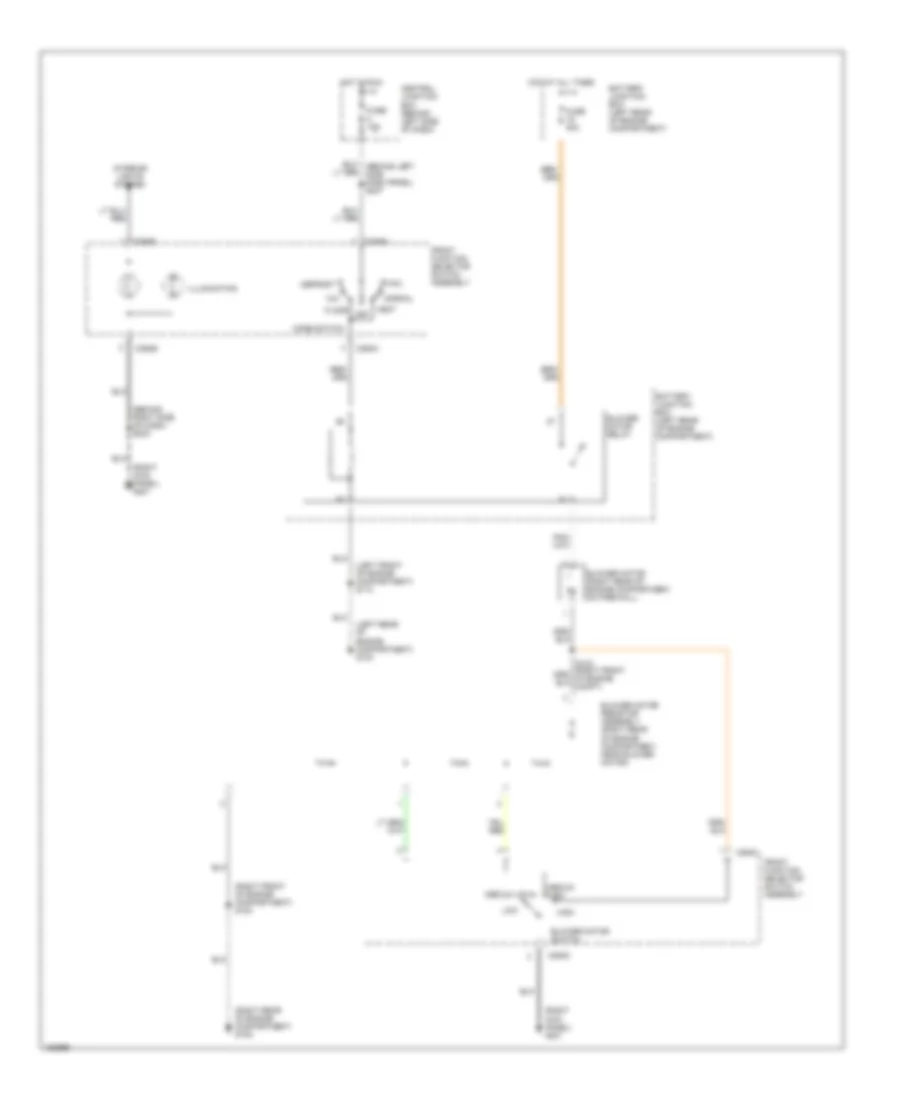
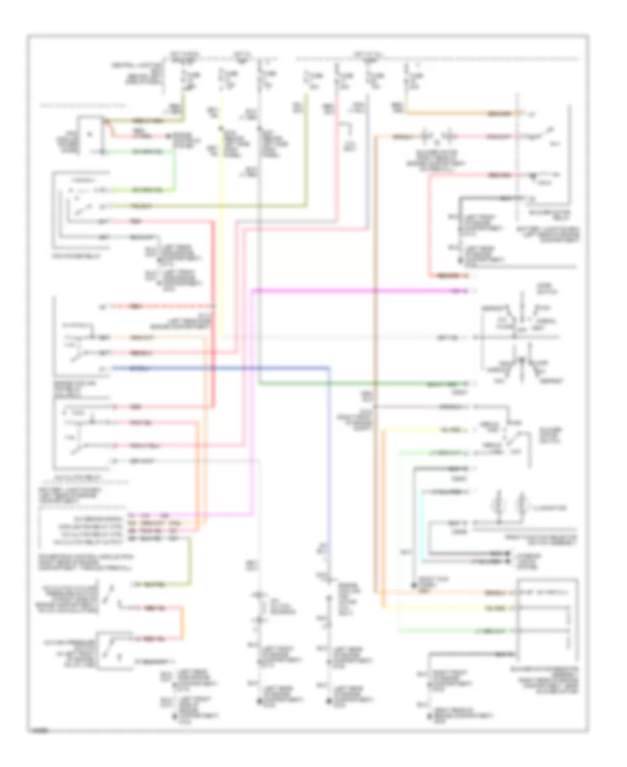
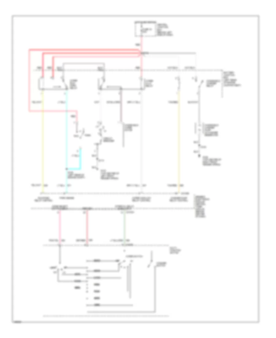
AIR CONDITIONING Heater Wiring Diagram for Ford Ranger 2002 List of elements for Heater Wiring Diagram for Ford Ranger 2002: 34 (behind right side of dash) s203 (left front of engine compartment) s110 (left rear of engine compartment) g103 (right front of engine compartment) s123 (right kick panel) g201 (right rear of engine compartment) g105 Battery junction box (left rear of engine compartment) Blower motor (right rear of engine compartment, on firewall) Blower motor relay Blower motor resistor assembly (right rear of engine compartment, near blower motor) Blower motor switch C294a C294b C294c Central junction box (behind left side of dash) Defrost Floor Front function selector switch assembly Fuse 10a Fuse 40a High Hot at all times Hot in run Illumination Interior lights system Low Max Medium high Medium low Mix Mode switch Normal Off Vent Manual A/C Wiring Diagram for Ford Ranger 2002 List of elements for Manual A/C Wiring Diagram for Ford Ranger 2002: 61 (left front side of engine compartment) g104 (left rear of engine compartment) g103 (left rear of engine compartment) s108 (right kick panel) g201 (right rear of engine compartment) g105 2.3l only A/c clutch cycling pressure switch (in right side of engine compartment, on a/c accumulator) A/c clutch relay A/c clutch relay ctrl A/c clutch relay output A/c clutch solenoid A/c demand signal A/c high pressure switch (in left front of engine, on a/c line) Battery junction box (left rear of engine compartment) Blower motor (right rear of engine compartment, on firewall) Blower motor relay Blower motor resistor assembly (right rear of engine compartment, near blower motor) Blower motor switch C294a C294b C294c Central junction box (behind left side of dash) Cooling fan relay ctrl Defrost Engine controls system Engine cooling fan motor (2.3l only) Engine cooling fan relay (2.3l only) Floor Front function selector switch assembly Fuse 10a Fuse 25a Fuse 30a Fuse 40a Fuse 7.5a High Hot at all times Hot in run Hot in run or start Illumination Interior lights system Low Max Medium high Medium low Mix Mode switch Nca Normal Of engine compartment) s123 Off Pcm module power diode Pcm power relay Powertrain control module (pcm) (right rear of engine compartment, through firewall) Red S113 (left rear side engine compartment) S124 (right front of engine compt) S216 (behind left side dash panel) S237 (behind left side dash panel) Side engine compartment) g104 Side engine compartment) s118 Vent
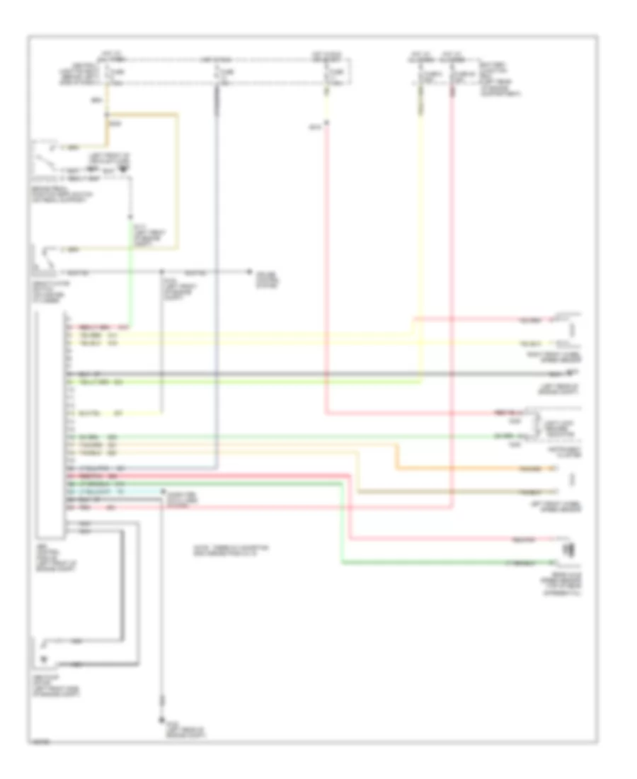
ANTI-LOCK BRAKES Anti-lock Brake Wiring Diagrams for Ford Ranger 2002 List of elements for Anti-lock Brake Wiring Diagrams for Ford Ranger 2002: 35 (left front of vehicle floor) g205 (left rear of engine compt) Abs control module (left front of engine compt) Abs pump motor (left front side of engine compt) Anti-lock brakes indicator Battery junction box (left rear of engine compartment) Brake pedal position (bpp) switch (on pedal support) C220 Central junction box (behind left side of dash) Computer data lines system Cruise control system Deactivator switch (on master cylinder) Differential) Fuse 10a Fuse 28 30a Fuse 6 50a Fuse 7.5a G102 G102 (left rear of engine compt) Hot at all times Hot in run Hot in run or start Instrument cluster Left front wheel speed sensor Nca Note: there is a shorting bar across pins 8 & 16 Ohms Rear axle speed sensor (top of rear Red Red/pnk Right front wheel speed sensor S103 (left front of engine compt) S117 (left front of engine compt) S218 S238
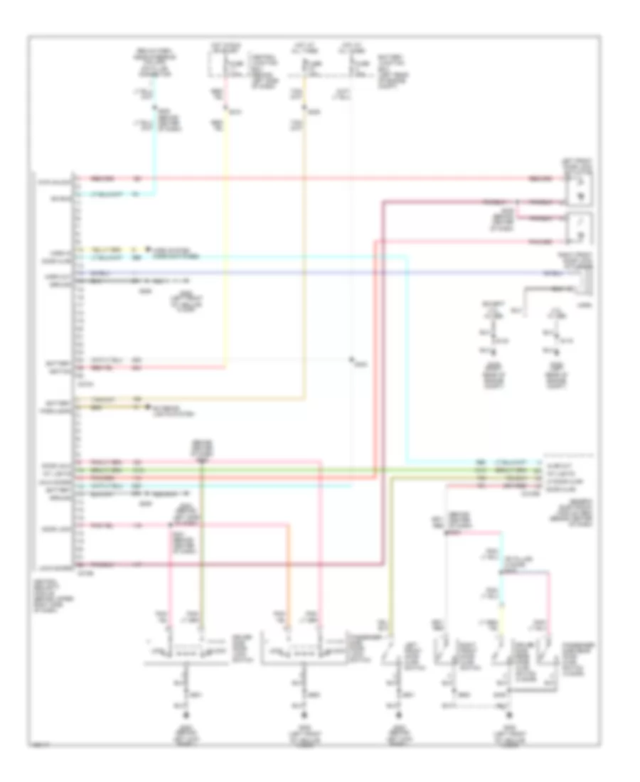
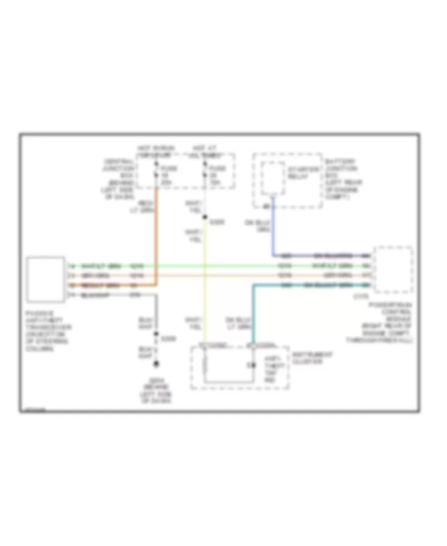
ANTI-THEFT Forced Entry Wiring Diagram for Ford Ranger 2002 List of elements for Forced Entry Wiring Diagram for Ford Ranger 2002: 64 (behind center of dash) s234 (behind center of dash) s240 (below dash, near steering column) data link connector (except 2.3l w/ abs 2.3l w/ abs Ajar out Battery Battery junction box (left rear of engine compt) C2100b C274a C274b Central junction box (behind left side of dash) Central security module (behind upper right side of dash) Door ajar Door lock Door unlk Driver side door lock switch Driver side rear door ajar switch (4 door) Dvr unlock Exterior lights system Fuse 15a Fuse 20a Fuse 7.5a G103 (left rear of engine compt) G105 (right rear of engine compt) G200 (behind left kick panel) G204 (behind left side of dash) G205 (left front of vehilce floor) Generic electronic module (gem) (behind center of dash) Ground Horn Horn in Horn out Horn system (horn switches) Hot at all times Hot in run or start Ignition Int lights Iso bus Left front door ajar switch Left front door lock actuator Lf door ajar Lock Lock doors Parklamps Passenger side door lock switch Passenger side rear door ajar switch (4 door) Right front door ajar switch Right front door lock actuator S119 S123 S206 S208 (behind center of dash) S209 S218 S235 S239 (behind center of dash) S241 (behind center of dash) S242 S409 S501 S600 Unlk doors Unlock Passive Anti-theft Wiring Diagram for Ford Ranger 2002 List of elements for Passive Anti-theft Wiring Diagram for Ford Ranger 2002: 17 Anti- theft "on" ind Battery junction box (left rear of engine compt) C175 C220a C220c Central junction box (behind left side of dash) Fuse 10a Fuse 25a G204 (behind left side of dash) Hot at all times Hot in run or start Instrument cluster Passive anti-theft transceiver (on bottom of steering column) Powertrain control module (right rear of engine compt, through firewall) S205 S209 Starter relay
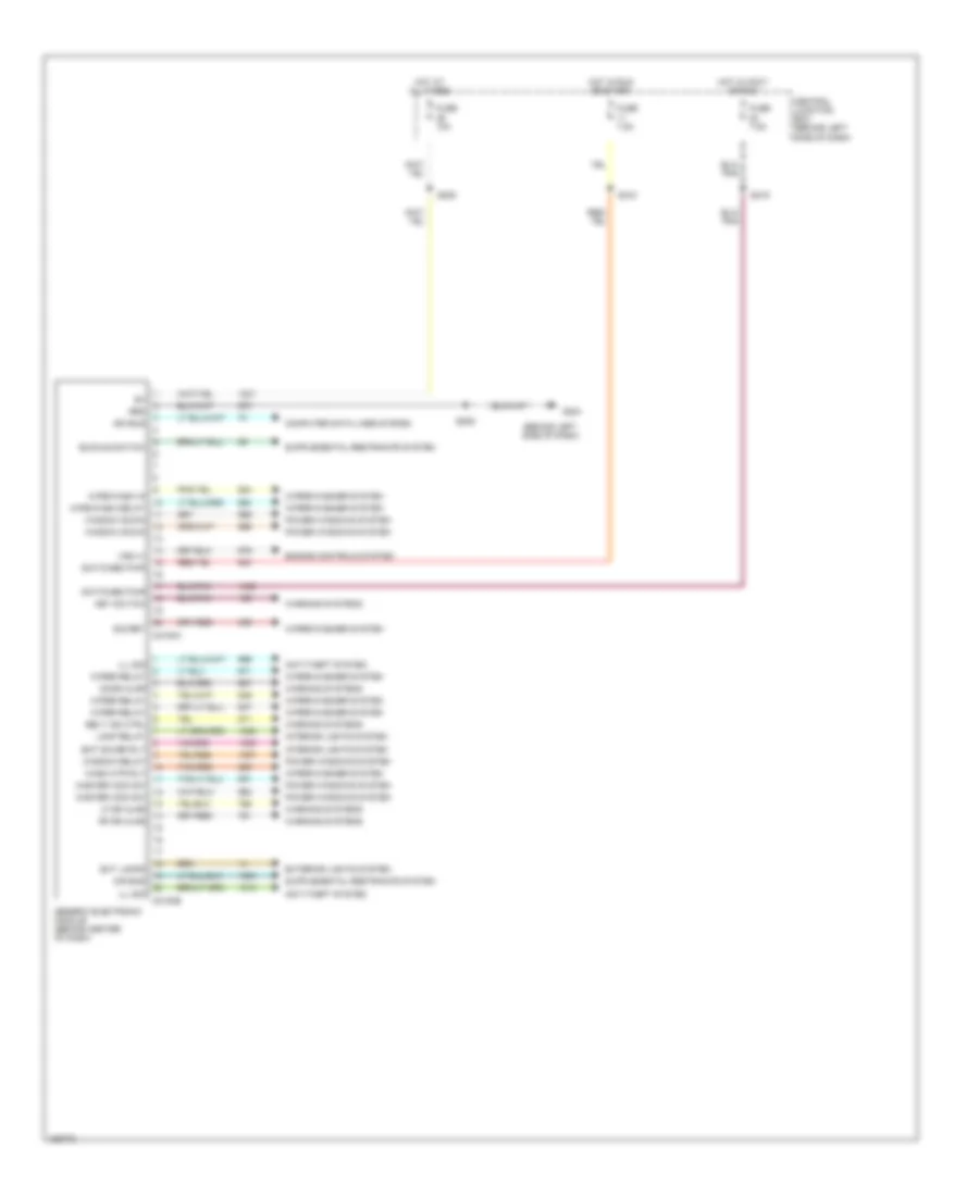
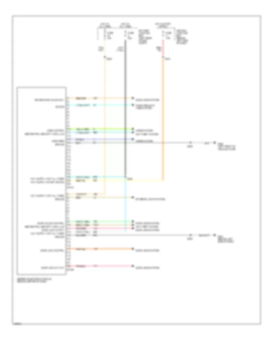
BODY COMPUTER Body Computer Wiring Diagrams (1 of 2) for Ford Ranger 2002 List of elements for Body Computer Wiring Diagrams (1 of 2) for Ford Ranger 2002: 47 (behind left side of dash) Air bag Anti-theft system Bat saver rly Belt ind ctrl Buckle switch C2100a C2100b Central junction box (behind left side of dash) Computer data lines system Door ajar Engine controls system Ext lamps Exterior lights system Fuse 10a Fuse 7.5a G204 Generic electronic module (behind center of dash) Grd Hot at all times Hot in accy or run Hot in run or start Ill sig Interior lights system Iso bus Key switch Lamp relay Lf dr ajar Master wdo sw Power windows system Rf dr ajar S205 S209 S218 S219 Sig ret Switched pwr Tan/red Vss (+) Warning systems Wash mtr rly Window down Window relay Wipe/wash delay Wipe/wash in Wiper relay Wiper/washer system Body Computer Wiring Diagrams (2 of 2) for Ford Ranger 2002 List of elements for Body Computer Wiring Diagrams (2 of 2) for Ford Ranger 2002: 32 Anti-theft system Battery junction box (left rear of eng compt) C274a C274b Central junction box (behind left side of dash) Computer data lines system Door lock control Door lock out put Door lock output Door locks system Door unlock control Driver door unlock rly Exterior lights system Fuse 15a Fuse 20a Fuse 7.5a G204 (behind left side of dash) G205 (left front of vehicle floor) Gem/central security mod illum Generic electronic module (behind center of dash) Ground Horn control Horn feed Horns system Hot at all times Hot in start or run Iso bus S206 S209 S218 S235 S242
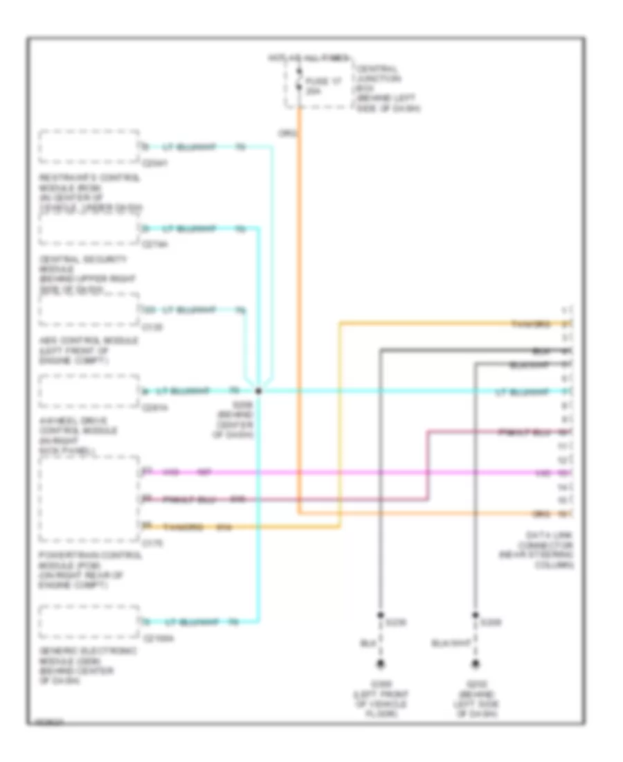
COMPUTER DATA LINES Computer Data Lines for Ford Ranger 2002 List of elements for Computer Data Lines for Ford Ranger 2002: 21 4-wheel drive control module (in right kick panel) Abs control module (left front of engine compt) C135 C175 C2041 C2100a C274a C281a Central junction box (behind left side of dash) Central security module (behind upper right side of dash) Data link connector (near steering column) Fuse 17 20a G202 (behind left side of dash) G300 (left front of vehicle floor) Generic electronic module (gem) (behind center of dash) Hot at all times Powertrain control module (pcm) (on right rear of engine compt) Restraints control module (rcm) (in center of vehicle, under dash) S208 (behind center of dash) S209 S236
COOLING FAN
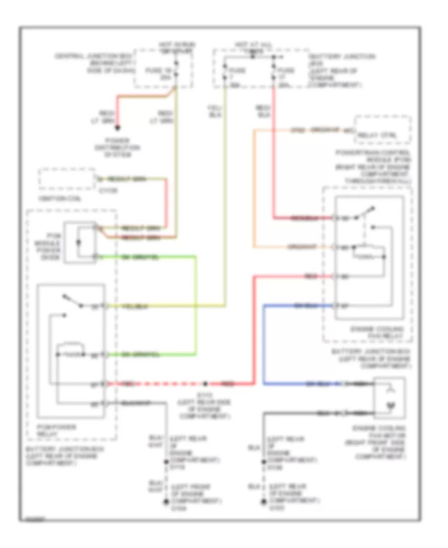
2.3L 2.3L, Cooling Fan Wiring Diagram for Ford Ranger 2002 List of elements for 2.3L, Cooling Fan Wiring Diagram for Ford Ranger 2002: 21 (left front of engine compartment) g104 (left rear of engine compartment) g103 Battery junction box (left rear of engine compartment) C1136 Central junction box (behind left side of dash) Engine compartment) s108 Engine cooling fan motor (right front side of engine compartment) Engine cooling fan relay Fuse 19 25a Fuse 30a Hot at all times Hot in run or start Ignition coil Nca Pcm module power diode Pcm power relay Power distribution system Powertrain control module (pcm) (right rear of engine compartment, through firewall) Red Relay ctrl S113 (left rear side of engine compartment)
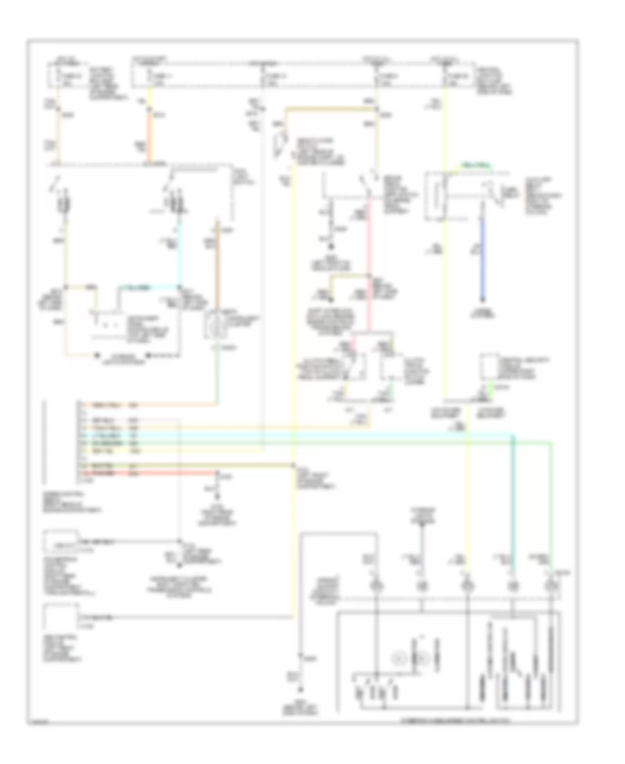
CRUISE CONTROL Cruise Control Wiring Diagram for Ford Ranger 2002 List of elements for Cruise Control Wiring Diagram for Ford Ranger 2002: 71 1000 ohms 120 ohms 15a 680 ohms 7.5a A/t Abs control module (left front of engine compartment) Air bag sliding contact (steering column) Auxiliary relay box 1 (behind dash, right of steering column) Battery junction box (bjb) (left rear of engine compartment) Brake pedal position (bpp) switch (on brake pedal support) C122 C135 C175 C205 C218a C220a C274a Central junction box (cjb) (behind left side of dash) Central security module (upper right side of dash) Clutch pedal position switch (top of clutch pedal support) Clutch triple function switch jumper Coast Deactivator switch (left rear of engine compt, on master cylinder) Fuse 10 Fuse 11 Fuse 33 Fuse 35 Fuse 9 G105 (right rear of engine compartment) G204 (behind left side of dash) G205 (left front of vehicle floor) Head Horn Horn relay Horns systems Hot at all times Hot in run Hot in start or run Illumination Instrument cluster Instrument cluster, body computer, transmission controls systems Instrument panel dimming module (top left side of dash) Interior lights systems M/t Main light switch Of dash) Off Park Powertrain control module (right rear of engine compartment, through firewall) Rest Resume S103 (left front of engine compartment) S116 (left rear of engine compartment) S123 S209 S215 (behind left side of dash) S216 S218 S235 S236 S238 Set/accelerate Shift interlock, anti-lock brakes, engine controls, transmissions systems Speed cntrl off 2200 ohms Speed control servo (right rear of engine compartment) Speed control on Steering wheel/speed control switch Vss out W/o power equipment W/power equipment
ENGINE PERFORMANCE
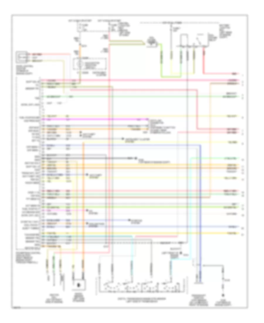
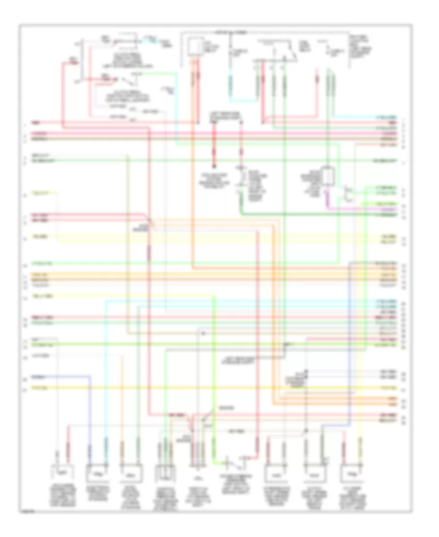
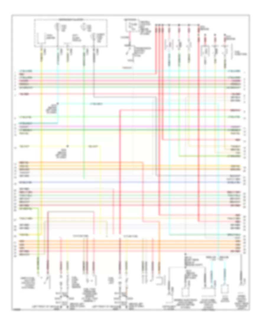
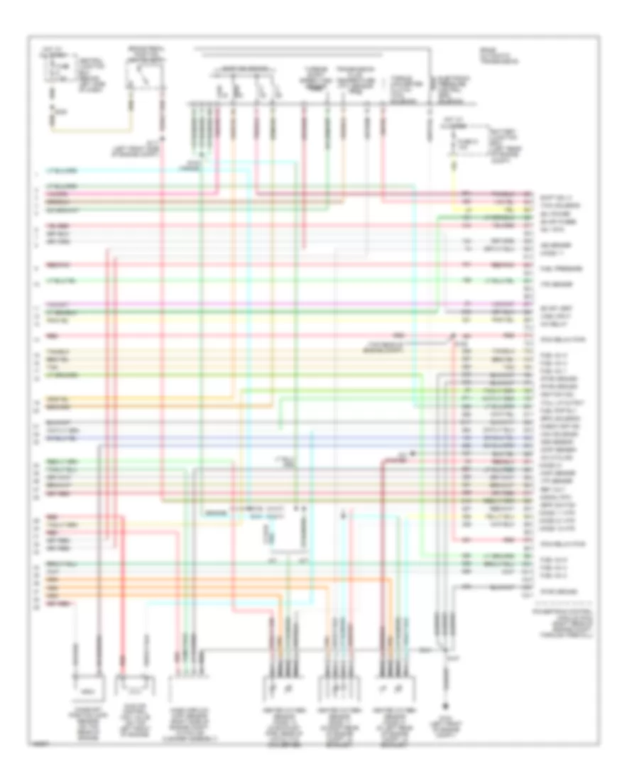
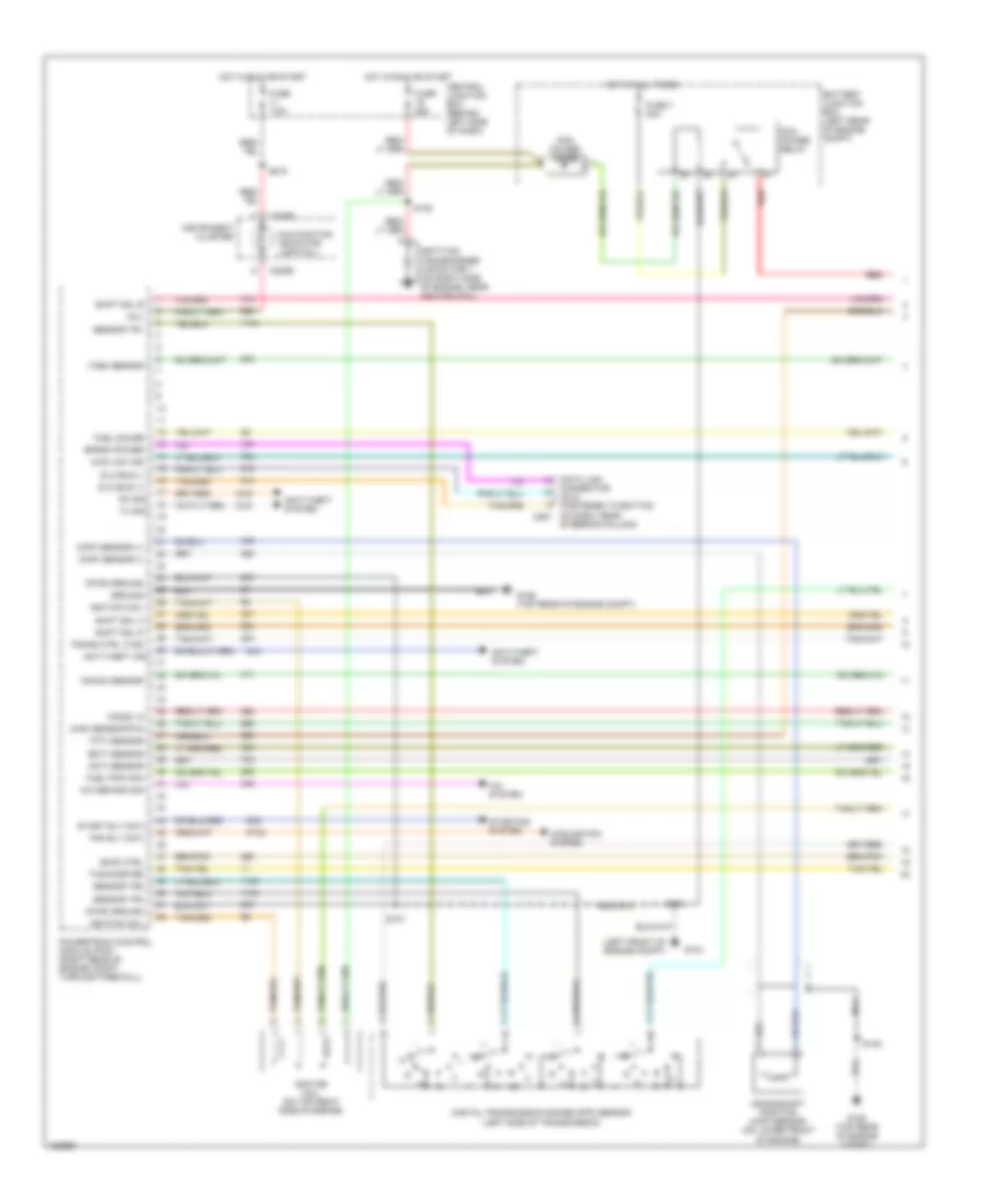
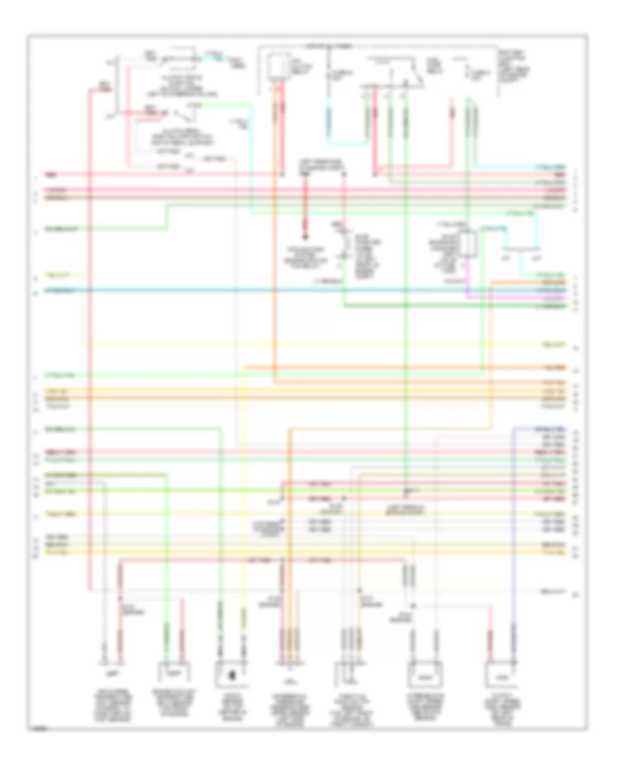
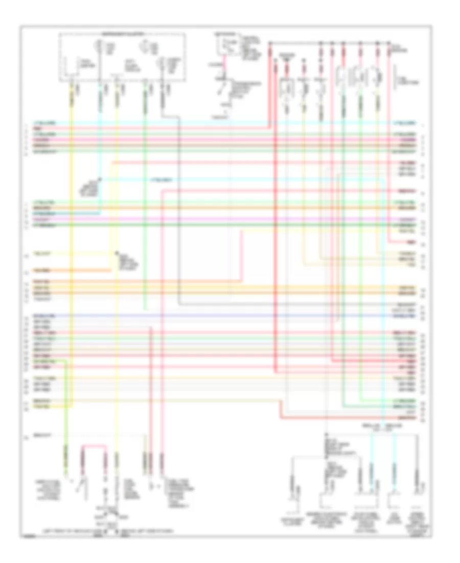
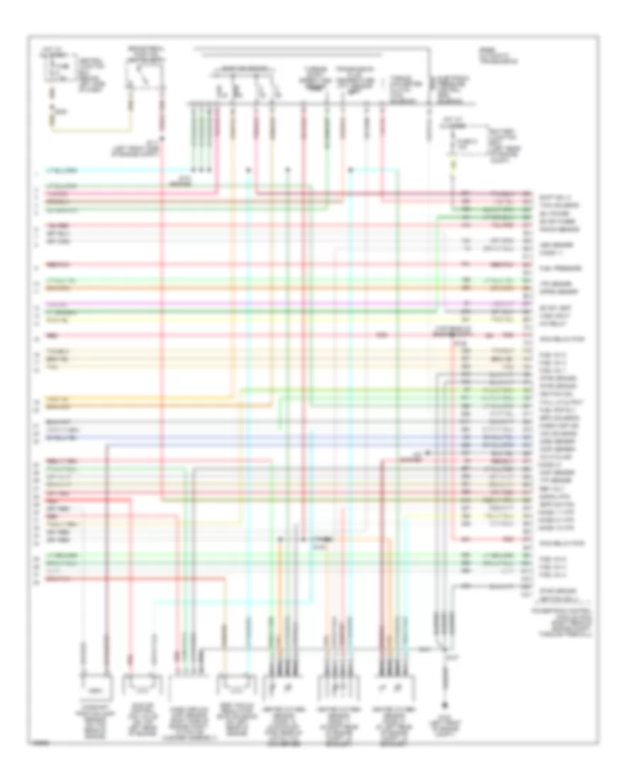
2.3L 2.3L, Engine Performance Wiring Diagrams (1 of 4) for Ford Ranger 2002 List of elements for 2.3L, Engine Performance Wiring Diagrams (1 of 4) for Ford Ranger 2002: 70 (fastened to bottom of dash, near steering column) (left front of engine compt) A/c demand sig A/c system Act sens in Anti-theft ind Anti-theft system Battery junction box (left rear of engine compt) C220b C251 Ccs Central junction box (behind left side of dash) Ckp sens + Ckp sens - Cool fan rly Cooling fans system Crankshaft position (ckp) sensor (on lower right front of engine) Data link connector (dlc) Digital transmission range (dtr) sensor (left side of transmission) Ect in Elect thermo Fuel pump/gauge Fuse 25a Fuse 7 30a Fuse 7.5a G104 G106 (top rear of engine compt) Gnd Ho2s 11 in Hot at all times Hot in run or start Ignition coil Ignition coil (on top right side of engine) Instrument cluster Instrument cluster system Knock sens Knock sensor (left side of engine) Maf sig Malfunction indicator lamp (mil) Mil Mod prog sig Nca Pcm power diode Pcm power relay Powertrain control module (pcm) (right rear of engine compt, through firewall) Psp sw Puel pump rly Red Rx sig S107 S118 S145 S218 Scp bus+ Scp bus- Sensor tr1 Sensor tr2 Sensor tr4 Shift sol a Shift sol b Start rly cntl Starting system Swirl cntl mon Swirl cntl sol Swirl control monitor (in rear of engine compt) Tachometer Tft sens in Trans cntl sw Tss Tx sig 2.3L, Engine Performance Wiring Diagrams (2 of 4) for Ford Ranger 2002 List of elements for 2.3L, Engine Performance Wiring Diagrams (2 of 4) for Ford Ranger 2002: 32 (engine) (left rear side of engine compt) (left rear side of engine compt) s113 (not used) A/c clutch relay A/t Air charge temperature (act) sensor (integral to mass airflow (maf) sensor) Battery junction box (left rear of engine compt) Clutch pedal position (cpp) switch (top of pedal support) Clutch pedal position (cpp) switch jumper (left of steering column) Cooling fans system (engine cooling fan relay) Cylinder head temperature (cht) sensor (on right side of cyl head) Electronic thermostat (on front of engine) Evap canister purge valve (in left front of engine compt) Evap emissions canister vent valve (at fuel tank) Fuel pump relay Fuse 23 20a Fuse 41 20a Hot at all times Intermediate shaft speed (iss) sensor (above dtr sensor) M/t Manifold absolute pressure (map) sensor (on center of firewall) Output shaft speed (oss) sensor (on left rear of trans) Power steering pressure (psp) switch (left front of engine compt) Red S111 S137 S143 (top rear of engine compt) S151 (engine) S152 (engine) Swirl control solenoid valve (on rear of engine) Throttle position (tp) sensor (on throttle body) 2.3L, Engine Performance Wiring Diagrams (3 of 4) for Ford Ranger 2002 List of elements for 2.3L, Engine Performance Wiring Diagrams (3 of 4) for Ford Ranger 2002: 34 (engine) s150 (left front of floor) g205 (left side of dash) g204 Anti- slosh module C122 C201b C220a C220b Central junction box (behind left side of dash) Check fuel cap ind Egr stepper motor (on rear of engine) Fuel injectors Fuel pump/ fuel gauge sensor Fuel tank pressure transducer sensor (at fuel tank assembly) Fuse 10a Generic electronic module (gem) (behind center of dash) Hot in run Inertia fuel shut-off (ifs) switch (in right kick panel) Instrument cluster Nca O/d off ind Red Red/pnk S149 (engine) S153 (engine) S209 S213 (behind left side of dash) S222 (behind left side of dash) S405 Speed control servo (right rear of engine compt) Tach- ometer Tan Tan/red Transmission control switch (tcs) 2.3L, Engine Performance Wiring Diagrams (4 of 4) for Ford Ranger 2002 List of elements for 2.3L, Engine Performance Wiring Diagrams (4 of 4) for Ford Ranger 2002: 66 (b+) power 5r44e automatic transmission A/c clutch rly A/c system A/t Battery junction box (left rear of engine compt) Bpp sw Brake pedal position switch (bpp) Camshaft position (cmp) sensor (on rear of engine) Canister vent Central junction box (behind left side of dash) Check cap ind Cht sensor Cmp sens in Egr step motor Electronic pressure control (epc) solenoid Epc sol Evap purge Fuel inj 1 Fuel inj 2 Fuel inj 3 Fuel inj 4 Fuel pump rly Fuel tank press Fuse 21 10a Fuse 7.5a G104 (left front of engine compt) Gnd Heated oxygen sensor (ho2s) 11 (in rear of engine compt, in exhaust) Heated oxygen sensor (ho2s) 12 (lower rear center of engine compt, in exhaust) Ho2s 11 heater Ho2s 11 in Ho2s 12 heater Hot at all times Iac valve Idle air control (iac) valve (top right rear of engine) Iss sens Knock sensor M/t Maf sensor Map sens Mass airflow (maf) sensor (right side of engine compt, within air cleaner assembly) Nca Oss sensor Pcm rly power Powertrain control module (pcm) (right rear of engine compt, through firewall) Red Red/pnk Ref voltage S107 S117 (left front side of engine compt) S154 (engine) S238 Shift sol c Shift solenoids Sig return Tan Tan/red Tcc sol Tcil Torque converter clutch (tcc) solenoid Tps in Tr sensor Transmission fluid temperature (tft) sensor Turbine shaft speed sensor (tss) Vss +
3.0L 3.0L, Engine Performance Wiring Diagrams (1 of 4) for Ford Ranger 2002 List of elements for 3.0L, Engine Performance Wiring Diagrams (1 of 4) for Ford Ranger 2002: 66 (ckp) sensor (+) (ckp) sensor (-) (dlc) (fastened to bottom of dash, near c251 (ect) sensor (ho2s) 12 (left front of engine compt) (maf) sensor rtn (mil) (pwr) ground (tft) sensor 4wd low ind A/c demand sig A/c system Act sens in Anti-theft ind Anti-theft system Battery junction box (left rear of engine compt) C fan rly cntl C220b Central junction box (behind left side of dash) Connector Cooling fan system Crankshaft position (ckp) sensor (on lower front of engine) Data link Digital transmission range (dtr) sensor (left side of transmission) Dlc bus (+) Dlc bus (-) Eprom power Fuel gauge Fuel pmp mon Fuse 25a Fuse 7 30a Fuse 7.5a G104 G106 (top rear of engine compt) Ground Hot at all times Hot in run or start Ignition coil Ignition coil (on top right side of engine) Instrument cluster Ks input Malfunction indicator lamp (mil) Nca Pcm power diode Pcm power relay Powertrain control module (pcm) (right rear of engine compt, through firewall) Red Rx sig S107 S118 S145 S218 Sensor tr1 Sensor tr2 Sensor tr4 Shift sol a Shift sol b Shift sol d Start rly cntl Starting system Steering column) Tachometer Trans ctrl (tcs) Tss Tx sig 3.0L, Engine Performance Wiring Diagrams (2 of 4) for Ford Ranger 2002 List of elements for 3.0L, Engine Performance Wiring Diagrams (2 of 4) for Ford Ranger 2002: 29 (a/t) (left rear side of engine compt) s113 (m/t) (not used) A/c clutch relay A/t Air charge temperature (act) sensor (integral to mass airflow (maf) sensor) Battery junction box (left rear of engine compt) Clutch pedal position (cpp) switch (top of pedal support) Clutch pedal position (cpp) switch jumper (left of steering column) Cooling fans system (engine cooling fan relay) Engine coolant temperature (ect) sensor (top front of engine) Evap canister purge valve (in left front of engine compt) Evap emissions canister vent valve (at fuel tank) Fuel pump relay Fuse 23 20a Fuse 41 20a Hot at all times Intermediate shaft speed (iss) sensor (above dtr sensor) Knock sensor (top right side of engine) M/t Nca Output shaft speed (oss) sensor (on left rear of trans) Red S111 (left rear side of engine compt) S137 (engine) S139 (engine) S143 (top rear of engine compt) Throttle position (tp) sensor (top left front of engine, on throttle body) 3.0L, Engine Performance Wiring Diagrams (3 of 4) for Ford Ranger 2002 List of elements for 3.0L, Engine Performance Wiring Diagrams (3 of 4) for Ford Ranger 2002: 41 (behind left side of dash) g204 (left front of vehicle) g205 4 x 4 mode switch 4wd low ind Anti- slosh module C122 C201b C220a C220b C281b Central junction box (behind left side of dash) Check fuel cap ind Four wheel drive control module (in right kick panel) Fuel injectors Fuel pump/ fuel gauge sensor Fuel tank pressure transducer sensor (at fuel tank assembly) Fuel tank unit Fuse 10a Generic electronic module (gem) (behind center of dash) Genuine 4x4 Hot in run Inertia fuel shut-off (ifs) switch (in right kick panel) Instrument cluster Nca O/d off ind Red Red/pnk Regular 4x4 S101 red (engine) S104 red (engine) S209 S213 (behind left side of dash) S215 (behind left side of dash) S222 (behind left side of dash) S405 Speed control servo (right rear of engine compt) Tach- ometer Tan Transmission control switch (tcs) W/ flex fuel W/o flex fuel 3.0L, Engine Performance Wiring Diagrams (4 of 4) for Ford Ranger 2002 List of elements for 3.0L, Engine Performance Wiring Diagrams (4 of 4) for Ford Ranger 2002: 76 (b+) power (bpp) switch (cmp) sensor (engine) (epc) solenoid (evap) purge (evap) vent (ho2s) 11 (ho2s) 11 htr (ho2s) 12 htr (ho2s) 21 (ho2s) 21 htr (iac) solenoid (maf) sensor (pcm relay) pwr (pwr) ground (tcc) solenoid (tcil) lp output (top rear of engine compt) (tp) sensor (tr) sensor (vss) input (w/a/t) (w/m/t) 5r44e automatic transmission A/c cycling A/c relay A/c system A/t Battery junction box (left rear of engine compt) Brake pedal position switch (bpp) Camshaft position (cmp) sensor (on top rear of engine) Central junction box (behind left side of dash) Check cap ind Electronic pressure control (epc) solenoid Fuel inj 1 Fuel inj 2 Fuel inj 3 Fuel inj 4 Fuel inj 5 Fuel inj 6 Fuel pmp rly Fuel pressure Fuse 21 10a Fuse 7.5a G104 (left front of engine compt) Heated oxygen sensor (ho2s) 11 (in right rear of engine compt, in exhaust) Heated oxygen sensor (ho2s) 12 (in exhaust pipe, rear of catalytic converter) Heated oxygen sensor (ho2s) 21 (in left rear of engine compt, in exhaust) Hot at all times Idle air control (iac) valve (on top left front of engine) Ignition coil Iss sensor Ks 1 rtn M/t Mass airflow (maf) sensor (right side of engine compt, within air cleaner assembly) Nca Oss sensor Powertrain control module (pcm) (right rear of engine compt, through firewall) Red Red/pnk Ref volt S100 (trans) S106 S107 S117 (left front side of engine compt) S129 S141 S238 Shift sol c Shift solenoids Signal rtn Tan Torque converter clutch (tcc) solenoid Transmission fluid temperature (tft) sensor Turbine shaft speed (tss) sensor
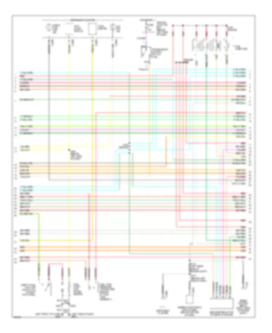
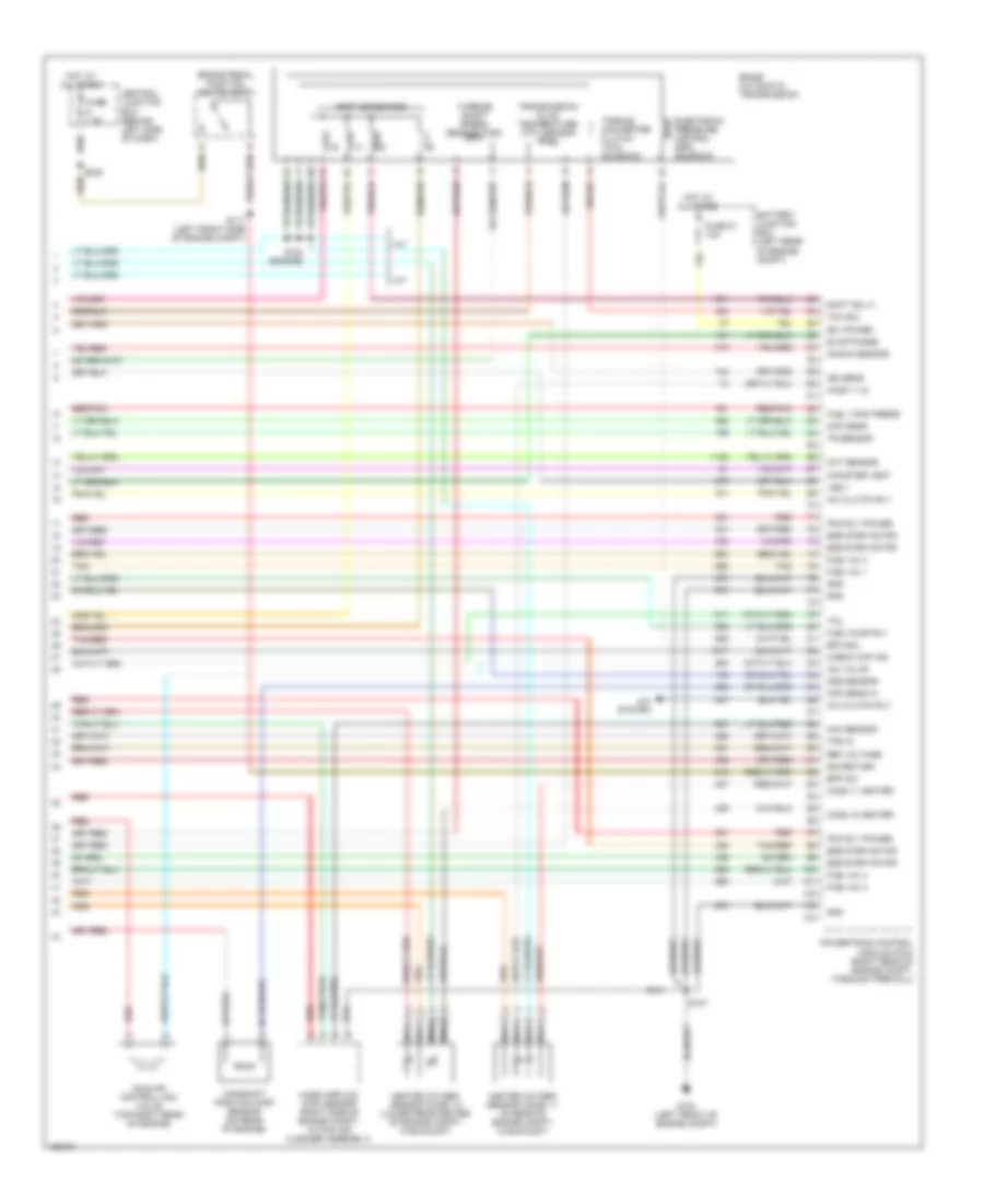
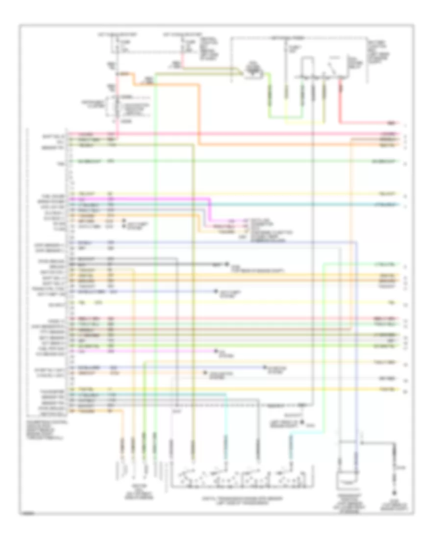
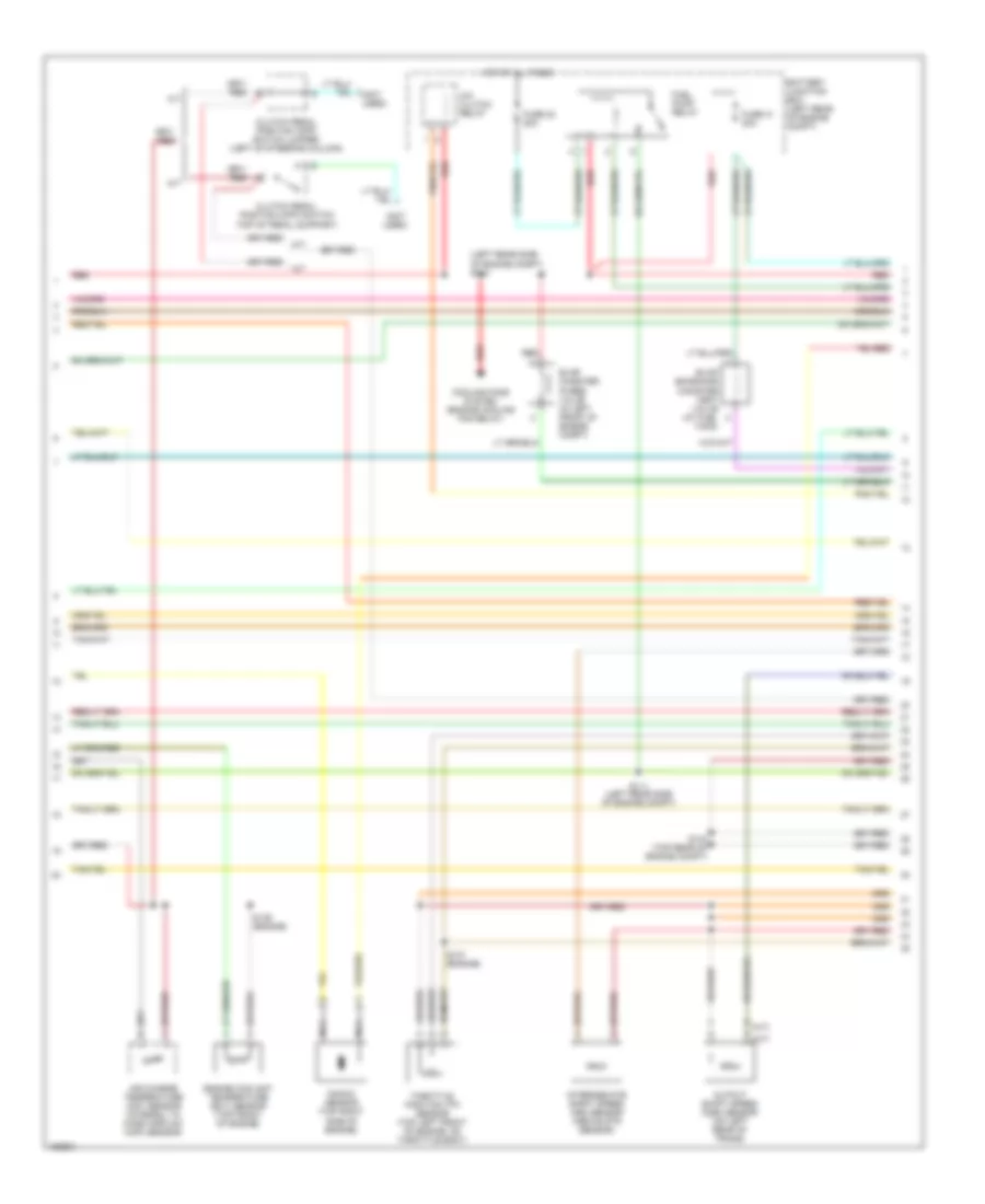
4.0L 4.0L, Engine Performance Wiring Diagrams (1 of 4) for Ford Ranger 2002 List of elements for 4.0L, Engine Performance Wiring Diagrams (1 of 4) for Ford Ranger 2002: 69 (act) sensor (ckp) sensor (+) (ckp) sensor (-) (dlc) (fastened to bottom of dash, near c251 (ect) sensor (evr) ctrl (ho2s) 12 (left front of engine compt) (maf) sensor rtn (mil) (pwr) ground (tft) sensor (tss) sensor 4wd low ind A/c demand sig A/c system Anti-theft ind Anti-theft system Battery junction box (left rear of engine compt) C220b Central junction box (behind left side of dash) Connector Cooling fan system Crankshaft position (ckp) sensor (on lower front of engine) Data link Digital transmission range (dtr) sensor (left side of transmission) Dlc bus (+) Dlc bus (-) Eprom power Fan rly cntl Fuel gauge Fuel pmp mon Fuse 25a Fuse 7 30a Fuse 7.5a G104 G106 (top rear of engine compt) Ground Hot at all times Hot in run or start Ignition coil Ignition coil (on top right side of engine) Igntition transformer capacitor 1 (on right side of engine, near ignition coil) Instrument cluster Knock sensor Malfunction indicator lamp (mil) Nca Pcm power diode Pcm power relay Powertrain control module (pcm) (right rear of engine compt, through firewall) Red Rx sig S105 S107 S118 S145 S218 Sensor tr1 Sensor tr2 Sensor tr4 Shift sol a Shift sol b Shift sol d Start rly cntl Starting system Steering column) Tachometer Trans ctrl (tcs) Tx sig 4.0L, Engine Performance Wiring Diagrams (2 of 4) for Ford Ranger 2002 List of elements for 4.0L, Engine Performance Wiring Diagrams (2 of 4) for Ford Ranger 2002: 33 (left rear of engine compt) (left rear side of engine compt) s113 (not used) (top rear of engine compt) A/c clutch relay A/t Air charge temperature (act) sensor (integral to mass airflow (maf) sensor) Battery junction box (left rear of engine compt) Clutch pedal position (cpp) switch (top of pedal support) Clutch triple function switch jumper (left of steering column) Cooling fans system (engine cooling fan relay) Differential pressure feedback egr (dpfe) sensor (left side of engine) Engine coolant temperature (ect) sensor (top front of engine) Evap canister purge valve (in left front of engine compt) Evap emissions canister vent valve (at fuel tank) Fuel pump relay Fuse 23 20a Fuse 41 20a Hot at all times Intermediate shaft speed (iss) sensor (above dtr sensor) Knock sensor (on top center of engine) M/t Nca Output shaft speed (oss) sensor (on left rear of trans) Red S111 S133 (engine) S135 (engine) S137 (engine) S139 (engine) S143 S144 (engine) Throttle position (tp) sensor (top left front of engine, on throttle body) 4.0L, Engine Performance Wiring Diagrams (3 of 4) for Ford Ranger 2002 List of elements for 4.0L, Engine Performance Wiring Diagrams (3 of 4) for Ford Ranger 2002: 38 (behind left side of dash) g204 (engine) s101 (left front of vehicle floor) g205 4wd low ind 4x4 mode switch Anti- slosh module C122 C201b C220a C220b C281b Central junction box (behind left side of dash) Check fuel cap ind Four wheel drive control module (in right kick panel) Fuel injectors Fuel pump/ fuel gauge sensor Fuel tank pressure transducer sensor (at fuel tank assembly) Fuse 10a Generic electronic module (gem) (behind center of dash) Genuine 4x4 Hot in run Inertia fuel shut-off (ifs) switch (in right kick panel) Instrument cluster Nca O/d off ind Red Red/pnk Regular 4x4 S104 (engine) S209 S213 (behind left side of dash) S215 (behind left side of dash) S222 (behind left side of dash) S405 Speed control servo (right rear of engine compt) Tach- ometer Tan Transmission control switch (tcs) 4.0L, Engine Performance Wiring Diagrams (4 of 4) for Ford Ranger 2002 List of elements for 4.0L, Engine Performance Wiring Diagrams (4 of 4) for Ford Ranger 2002: 74 (b+) power (bpp) switch (cmp) sensor (dpfe) sensor (epc) solenoid (evap) purge (evap) vent (ho2s) 11 (ho2s) 11 htr (ho2s) 12 htr (ho2s) 21 (ho2s) 21 htr (iac) solenoid (iss) sensor (maf) sensor (oss) sensor (pcm relay) pwr (pwr) ground (tcc) solenoid (tcil) lp output (top rear of engine compt) (tp) sensor (tr) sensor (trans) (vss) input 5r55e automatic transmission A/c cycling A/c relay A/c system Battery junction box (left rear of engine compt) Brake pedal position switch (bpp) Camshaft position (cmp) sensor (on top rear of engine) Central junction box (behind left side of dash) Check cap ind Egr vacuum regulator (evr) solenoid (on left rear of engine) Electronic pressure control (epc) solenoid Fuel inj 1 Fuel inj 2 Fuel inj 3 Fuel inj 4 Fuel inj 5 Fuel inj 6 Fuel pmp rly Fuel pressure Fuse 21 10a Fuse 7.5a G104 (left front of engine compt) Heated oxygen sensor (ho2s) 11 (in right rear of engine compt, in exhaust) Heated oxygen sensor (ho2s) 12 (in exhaust pipe, rear of catalytic converter) Heated oxygen sensor (ho2s) 21 (in left rear of engine compt, in exhaust) Hot at all times Idle air control (iac) valve (on top left rear of engine) Ignition coil Ignition coil 4 Knock sensor Mass airflow (maf) sensor (right side of engine compt, within air cleaner assembly) Nca Powertrain control module (pcm) (right rear of engine compt, through firewall) Red Red/pnk Ref volt S107 S117 (left front side of engine compt) S129 S140 S141 (engine) S238 Shift sol c Shift solenoids Signal rtn Tan Torque converter clutch (tcc) solenoid Transmission fluid temperature (tft) sensor Turbine shaft speed (tss) sensor
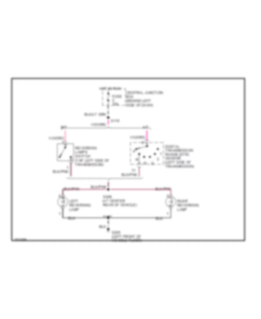
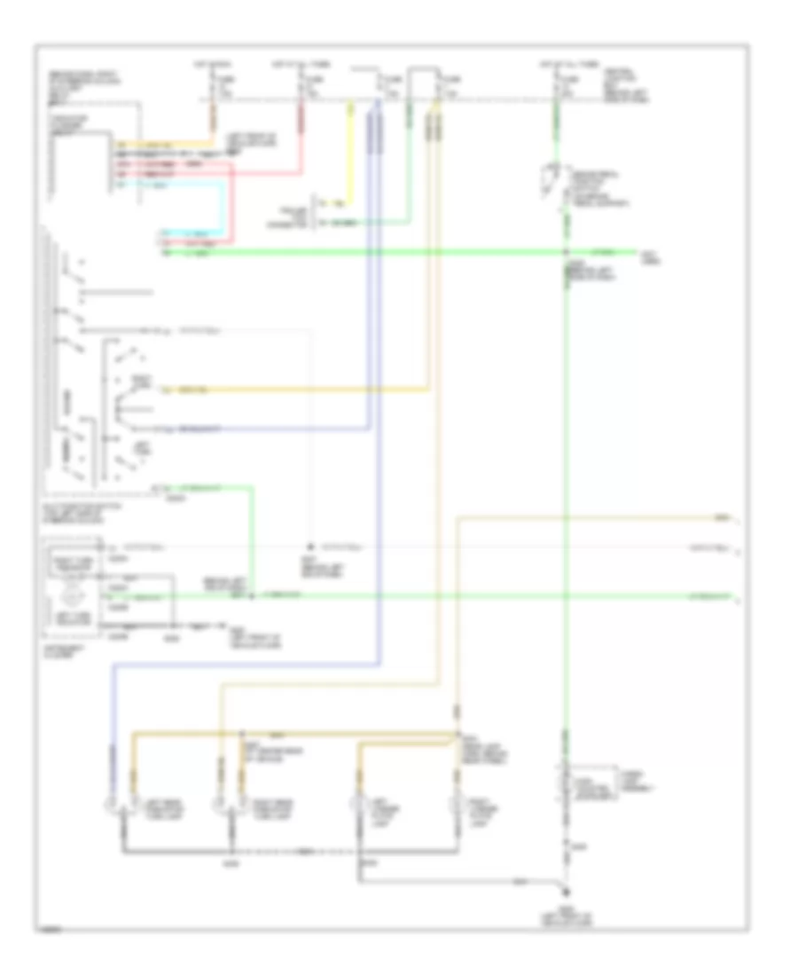
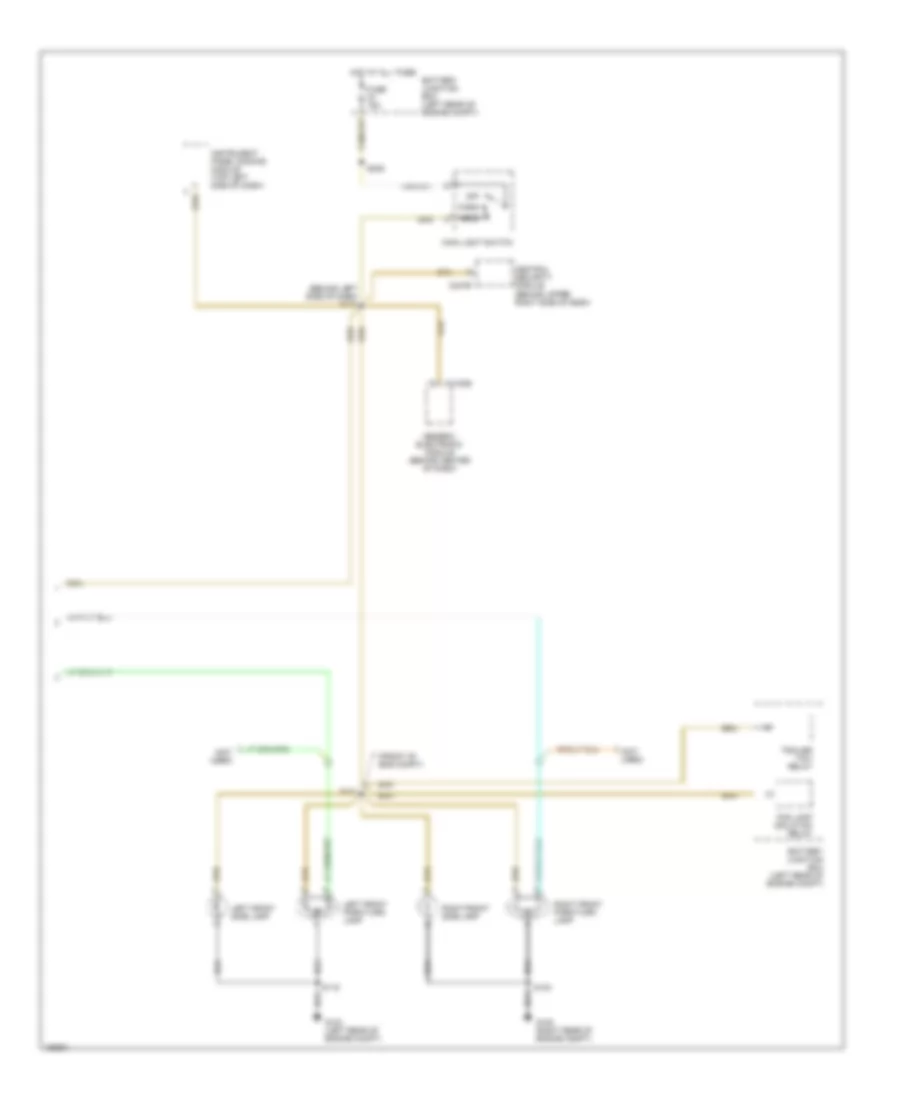
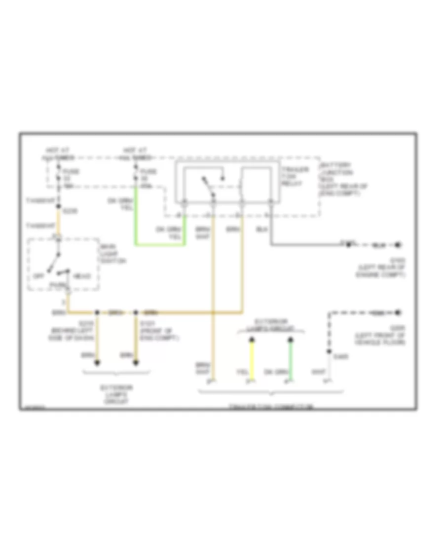
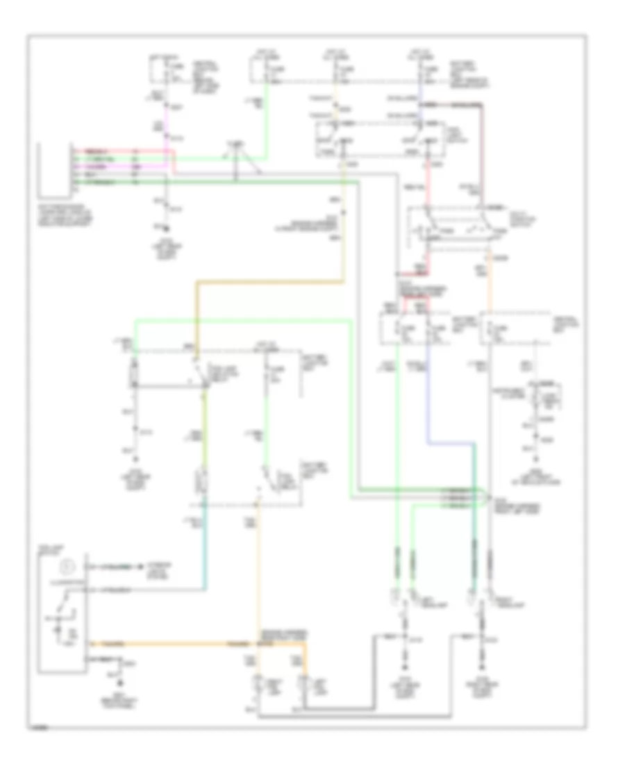
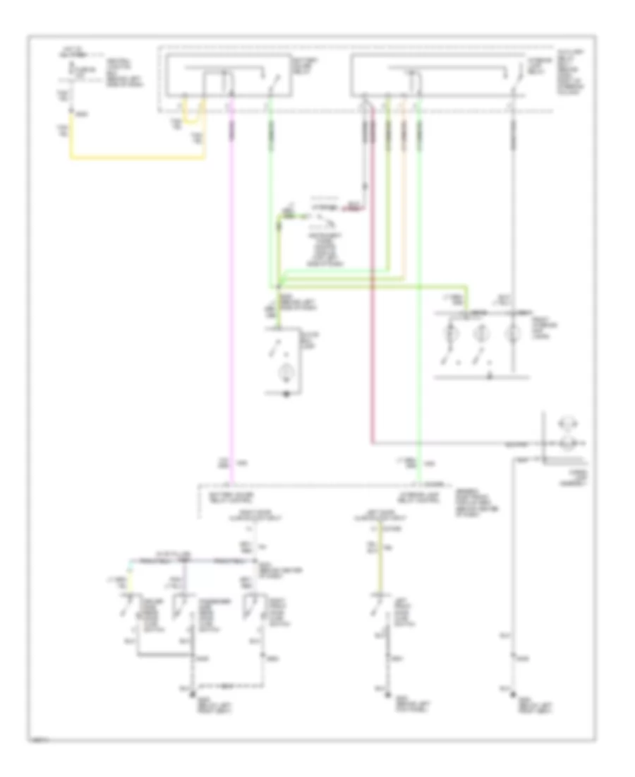
EXTERIOR LIGHTS Back-up Lamps Wiring Diagram for Ford Ranger 2002 List of elements for Back-up Lamps Wiring Diagram for Ford Ranger 2002: 13 A/t Central junction box (behind left side of dash) Digital transmission range (dtr) sensor (left side of transmission) Fuse 10a G205 (left front of vehicle floor) Hot in run Left reversing lamp M/t Reversing lamps switch (top left side of transmission) Right reversing lamp S115 S406 S408 (at center rear of vehicle) Exterior Lamps Wiring Diagram (1 of 2) for Ford Ranger 2002 List of elements for Exterior Lamps Wiring Diagram (1 of 2) for Ford Ranger 2002: 41 (behind dash, right of steering column) auxiliary relay box 1 (behind left sie of dash) s211 (left front of vehicle floor) g205 (not used) 87a Brake pedal position switch (on brake pedal support) C202a C220a C220b Cargo lamp assembly Central junction box (behind left side of dash) Fuse 15a Fuse 20a Fuse 7.5a G205 (left front of vehicle floor) G20f (left front of vehicle floor) Hazard High mounted stoplamp Hot at all times Hot in run Indicator flasher relay Instrument cluster Left license plate lamp Left rear park/stop/ turn lamp Left turn Left turn indicator Multi-function switch (top left side of steering column) Normal Right license plate lamp Right rear park/stop/ turn lamp Right turn Right turn indicator S206 S207 (behind left sie of dash) S236 S404 (rear lamp harn, behind rear wheel) S405 S406 S407 (at center rear of vehicle) S409 Trailer tow connector Exterior Lamps Wiring Diagram (2 of 2) for Ford Ranger 2002 List of elements for Exterior Lamps Wiring Diagram (2 of 2) for Ford Ranger 2002: 27 (behind left side of dash) s215 (front of eng compt) (not used) Battery junction box (left rear of engine compt) C2100b C247b Central security module (behind upper right side of dash) Fog lamp isolation relay Fuse 15a G103 (left rear of engine compt) G105 (right rear of engine compt) Generic electronic module (behind center of dash) Head Hot at all times Instrument panel dimming module (top left side of dash) Left front park/turn lamp Left front side lamp Main light switch Off Park Right front park/turn lamp Right front side lamp S119 S121 S123 S235 Trailer tow relay Trailer Tow Wiring Diagram for Ford Ranger 2002 List of elements for Trailer Tow Wiring Diagram for Ford Ranger 2002: 17 Battery junction box (left rear of eng compt) Exterior lamps circuit Fuse 15a G103 (left rear of engine compt) G205 (left front of vehicle floor) Head Hot at all times Main light switch Off Park S110 S121 (front of eng compt) S215 (behind left side of dash) S235 S405 Trailer tow connector Trailer tow relay
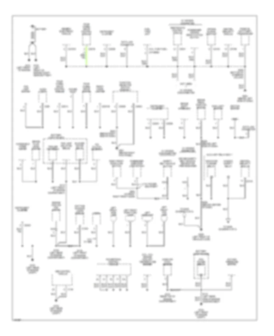
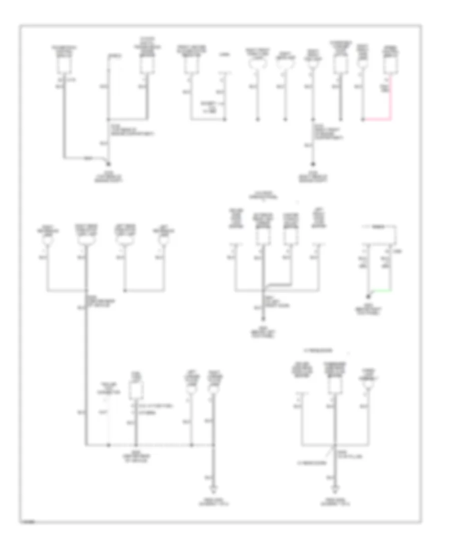
GROUND DISTRIBUTION Ground Distribution Wiring Diagram (1 of 2) for Ford Ranger 2002 List of elements for Ground Distribution Wiring Diagram (1 of 2) for Ford Ranger 2002: 92 (2.3l, 4.0l) engine coolant temperature sender (3.0l, flex fuel) (not used) (others) 2.3l w/ abs A/c clutch solenoid A/c high pressure switch Abs control module Air bag sliding contact Audio unit Auxiliary relay box 1 Battery Battery junction box Blower motor relay Brake fluid level switch Brake pedal position switch Brake shift interlock C1030 C135 C2031b C2041 C2100a C218a C220a C220b C220c C274a C274b C281a C281b C290 C294b C294c Central security module Data link connector Daytime running lamps module Driver safety belt buckle retractor pretensioner Engine cooling fan motor Fog lamp isolation relay Fog lamp switch Four- wheel drive control module Four- wheel drive switch Front cigar lighter Fuel tank unit Function selector switch assembly G100 (left front of engine compt, near battery) G101 (left front of engine) G102 (left rear of engine compt) G103 (left rear of engine compt) G104 (left front of engine compt) G201 (behind right kick panel) G204 (behind left side of dash) G205 (left front of vehicle floor) Generic electronic module Gnd Horn Ignition switch Indicator flasher relay Instrument cluster Left front fog lamp Left front park/turn lamp Left front side lamp Left headlamp Main light switch Mass air flow sensor Nca Passenger air bag deactivation switch Passenger side door lock switch Passive anti-theft transceiver Pcm power relay Power point Powertrain control module Restraints control module Right front door ajar switch S107 (rear top of engine compartment) S108 (left rear of engine compartment) S110 (left front of engine compartment) S118 (left rear side of engine compartment) S119 (left front of engine compartment) S203 (behind right side of dash) S206 (behind center of dash) S209 (bottom of steering column) S600 (in front right front door) Safety belt buckle switch To s405 (diagram 2 of 2) To s409 (diagram 2 of 2) Trailer tow relay W/ air bag connected W/ air bag disconnected W/ power equipment Window safety relay Windshield wiper motor Ground Distribution Wiring Diagram (2 of 2) for Ford Ranger 2002 List of elements for Ground Distribution Wiring Diagram (2 of 2) for Ford Ranger 2002: 45 (3.0l w/ flex fuel) (others) (w/4wd) digital transmission range sensor C175 C290 Cargo lamp assembly Driver side door lock switch Driver side rear door ajar switch Except 2.3l w/ abs Exterior rear view mirror switch From g300 (diagram 1 of 2) From s206 (diagram 1 of 2) Front heater blower motor resistor Fuel tank unit G105 (right rear of engine compt) G106 (top rear of engine compt) G200 (behind left kick panel) G203 (behind right kick panel) Horn Left front door ajar switch Left license plate lamp Left rear park/stop turn lamp Left reversing lamp Master window adjust switch Nca Passenger side rear door ajar switch Powertrain control module Radio Right front fog lamp Right front park/turn lamp Right front side light Right headlamp Right license plate lamp Right rear park/stop turn lamp Right reversing lamp S123 (right front of engine compartment) S145 (top rear of engine compartment) S405 (center rear of vehicle) S409 (in "b" pillar) Shield Speed control servo Trailer tow connector W/ rear doors W/o roof opening panel Windshield washer pump motor
HEADLIGHTS Headlight Wiring Diagram for Ford Ranger 2002 List of elements for Headlight Wiring Diagram for Ford Ranger 2002: 56 (engine harness, rear right side) s122 10a 15a 20a 30a Battery junction box Battery junction box (left rear of engine compt) C202b C205 C220b Central junction box Central junction box (behind left side of dash) Daytime running lamps (drl) module (left side of lower radiator support) Fog lamp isolation relay Fog lamp relay Fog lamp switch Fuse Fuse 10a Fuse 15a Fuse 20a G103 (left rear of eng compt) G105 (right rear of eng compt) G201 (behind right kick panel) G205 (left front of vehicle ploor) Head High beam ind Hot at all times Hot in run Illumination Instrument cluster Interior lights system Left fog lamp Left headlamp Low Main light switch Multi- function switch Off On ind Park Pass Pass low Right fog lamp Right headlamp S110 S115 S119 S120 (engine harness, front left side) S121 (engine harness, in front engine compt) S123 S147 (engine harness, rear left side) S203 S226 S235 S236 S237 W/ drl
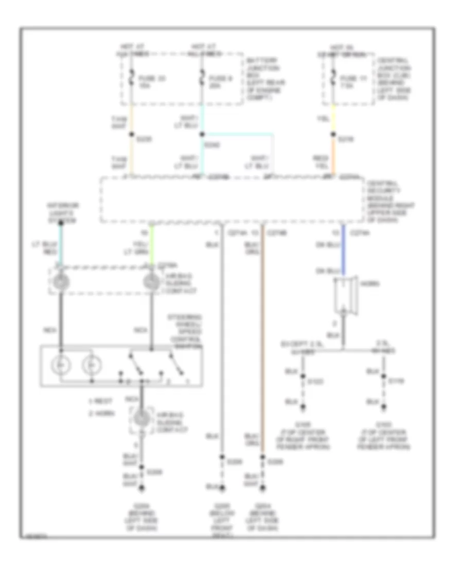
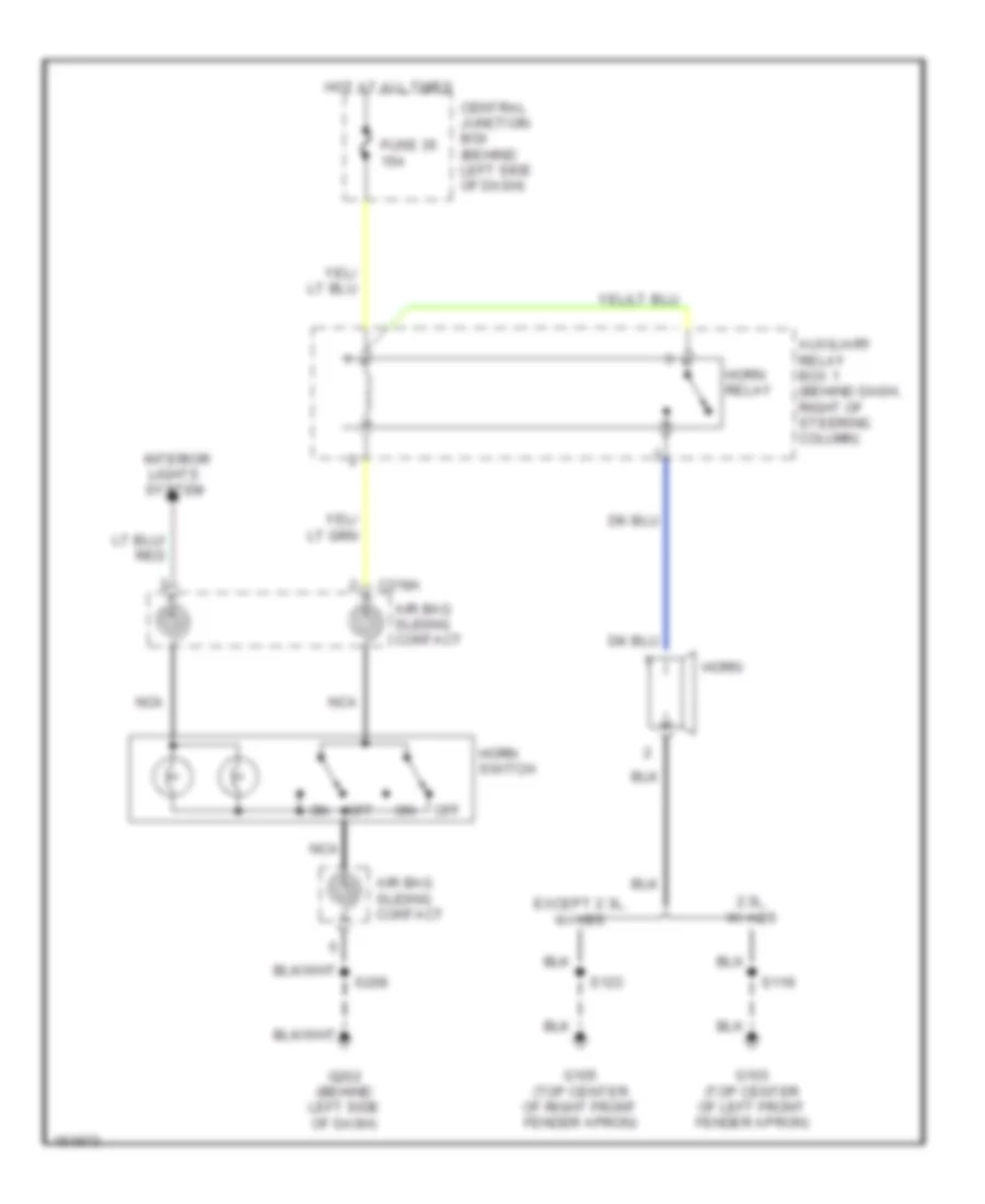
HORN Horn Wiring Diagram, with Power Equipment for Ford Ranger 2002 List of elements for Horn Wiring Diagram, with Power Equipment for Ford Ranger 2002: 30 2.3l, w/ abs Air bag sliding contact Battery junction box (left rear of engine compt) C218a C274a C274b Central junction box (cjb) (behind left side of dash) Central security module (behind right upper side of dash) Except 2.3l, w/ abs Fuse 11 7.5a Fuse 33 15a Fuse 8 20a G103 (top center of left front fender apron) G105 (top center of right front fender apron) G204 (behind left side of dash) G205 (below left front seat) Horn Hot at all times Hot in start or run Interior lights system Nca Rest S119 S123 S206 S209 S218 S235 S242 Steering wheel/ speed control switch Horn Wiring Diagram, without Power Equipment for Ford Ranger 2002 List of elements for Horn Wiring Diagram, without Power Equipment for Ford Ranger 2002: 20 2.3l, w/ abs Air bag sliding contact Auxiliary relay box 1 (behind dash, right of steering column) C218a Central junction box (behind left side of dash) Except 2.3l, w/ abs Fuse 35 15a G103 (top center of left front fender apron) G105 (top center of right front fender apron) G202 (behind left side of dash) Horn Horn relay Horn switch Hot at all times Interior lights system Nca Off S119 S123 S209
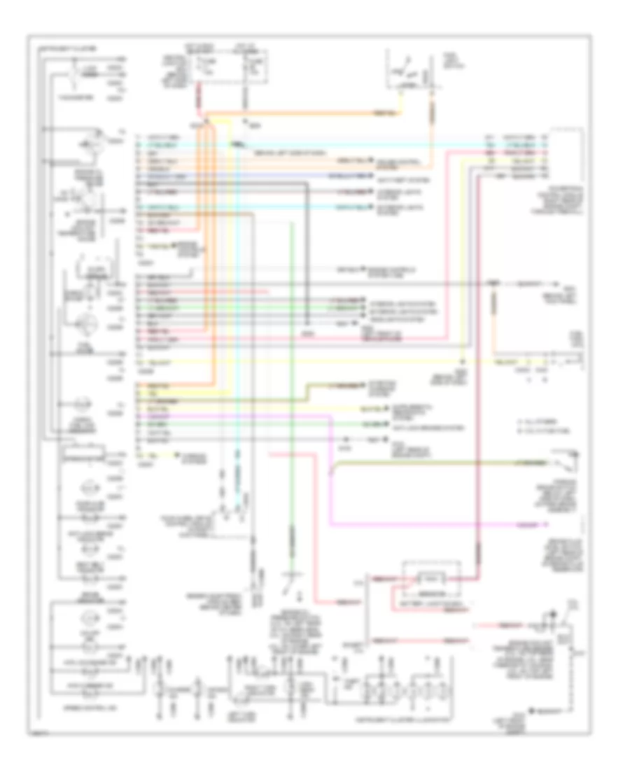
INSTRUMENT CLUSTER Instrument Cluster Wiring Diagram for Ford Ranger 2002 List of elements for Instrument Cluster Wiring Diagram for Ford Ranger 2002: 82 (behind left kick panel) (behind left side of dash) 2.3l 2.3l, 4.0l 4.32k ohms 4wd hi range ind 4wd low range ind A all others Air bag ind Anti-lock brake indicator Anti-lock brakes system Anti-theft system B 3.0l w/ flex fuel Battery junction box Brake fluid level switch (left rear of engine compt, on brake fluid reservoir) Brake indicator C2100b C220a C220b C220c C281b C4033 C433 Central junction box (behind left side of dash) Charge ind Check fuel cap indicator Check gauge Cruise control system Door ajar Door ajar indicator Engine controls system Engine controls system (vss) Engine coolant temperature gauge Engine coolant temperature sender (2.3l: on top rear of engine, 3.0l: near thermostat housing, 4.0l: on top left front of engine) Engine oil pressure gauge Engine oil pressure switch (2.3l: on left rear of cylinder head, 3.0l: on right rear of engine, 4.0l: on lower left front of engine) Except 2.3l Exterior lights system Four wheel drive control module (in right kick panel) Fuel gauge Fuel tank unit Fuse 10a Fuse 7.5a G103 (left rear of engine compt) G104 (left front of engine compt) G204 G205 (left front of vehicle floor) Generic electronic module (gem) (behind center of dash) Head Headlights system High beam ind Hot at all times Hot in run or start Instrument cluster Instrument cluster illumination Interior lights system Left turn indicator Main light switch O/d off ind Off Ohms Park Parking brake switch (below left side of dash, on park brake assembly) Powertrain control module (right rear of engine compt, through firewall) Resistor Right turn indicator S107 S108 S205 S209 S215 S218 S222 (behind left side of dash) S236 Seat belt indicator Slosh module Speed control ind Speedometer Starting/ charging system Tachometer Theft ind Warning systems
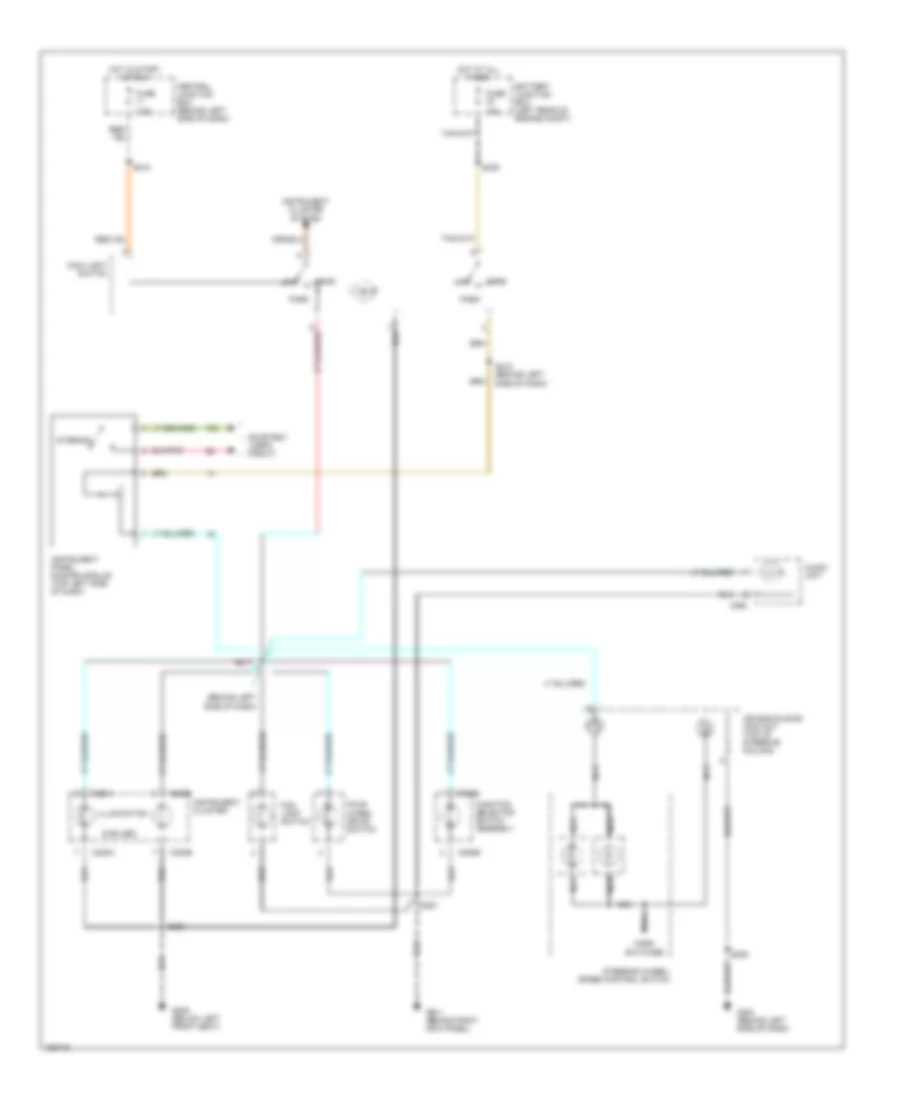
INTERIOR LIGHTS Courtesy Lamps Wiring Diagram for Ford Ranger 2002 List of elements for Courtesy Lamps Wiring Diagram for Ford Ranger 2002: 31 (in "b" pillar) s410 Auxiliary relay box 1 (behind dash, right of steering column) Battery saver relay Battery saver relay control C2100b C931a C931b Cargo lamp assembly Central juncton box (behind left side of dash) Driver side rear door ajar switch Front interior/ map lamps Fuse 26 10a G200 (behind left kick panel) G205 (below left front seat) Generic electronic module (gem) (behind center of dash) Glove box lamp Hot at all times Instrument panel dimming module (top left side of dash) Interior Interior lamp relay Interior lamp relay control Left door ajar switch input Left front door ajar switch Passenger side rear door ajar switch Right door ajar switch input Right front door ajar switch S205 S234 (behind center of dash) S409 S501 S600 Instrument Illumination Wiring Diagram for Ford Ranger 2002 List of elements for Instrument Illumination Wiring Diagram for Ford Ranger 2002: 41 (6 bulbs) (behind left side of dash) 15a 7.5a Air bag sliding contact (top of steering column) Audio unit Battery junction box (left rear of engine compt) C220a C220b C290 C294b Central junction box (behind left side of dash) Courtesy lamps circuit Fog lamp switch Four- wheel drive switch Function selector switch assembly Fuse G201 (behind right kick panel) G204 (behind left side of dash) G205 (below left front seat) Head Horn switches Hot at all times Hot in start or run Illumination Instrument cluster Instrument cluster system Instrument panel dimming module (top left side of dash) Interior Main light switch Nca Off Park S203 S209 S215 (behind left side of dash) S217 S218 S235 S236 Steering wheel/ speed control switch
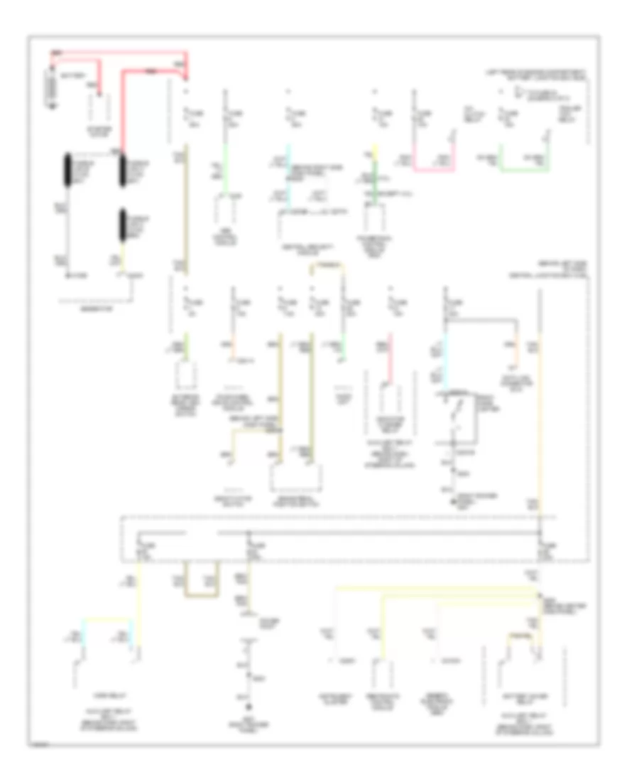
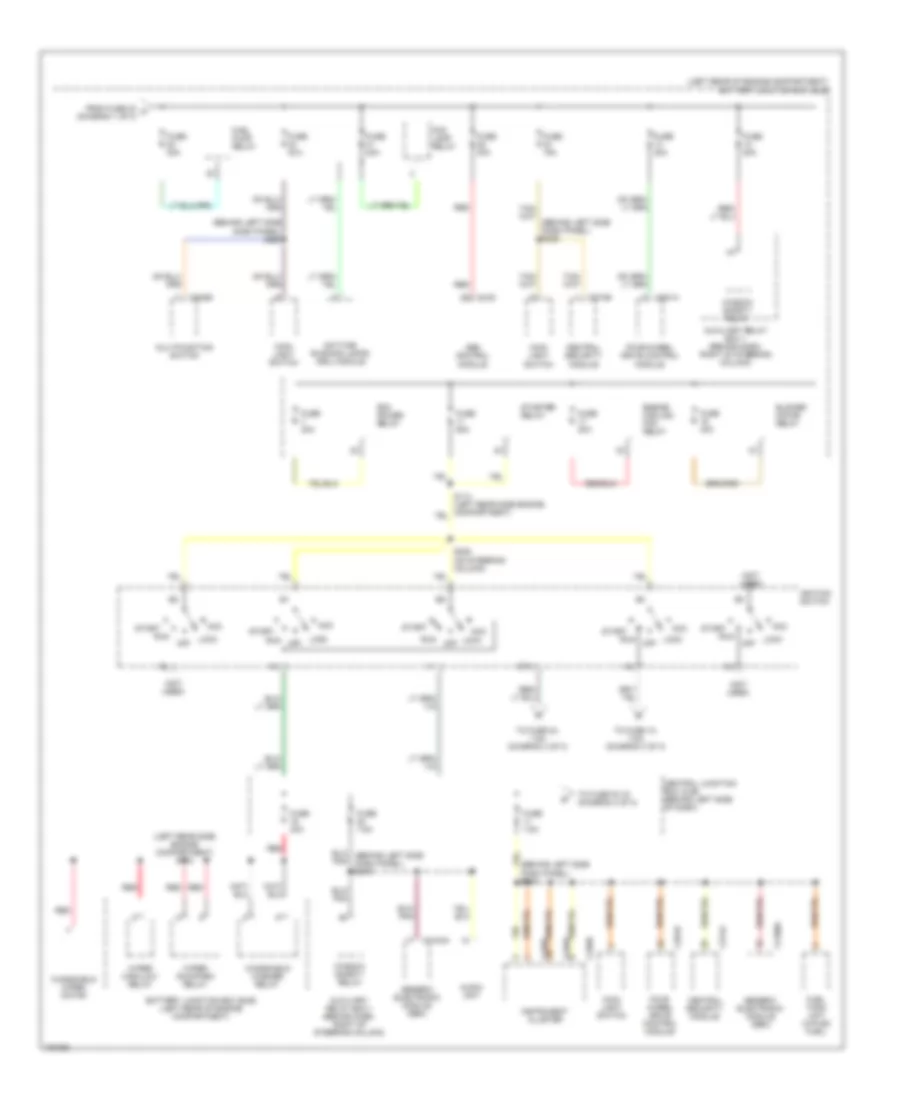
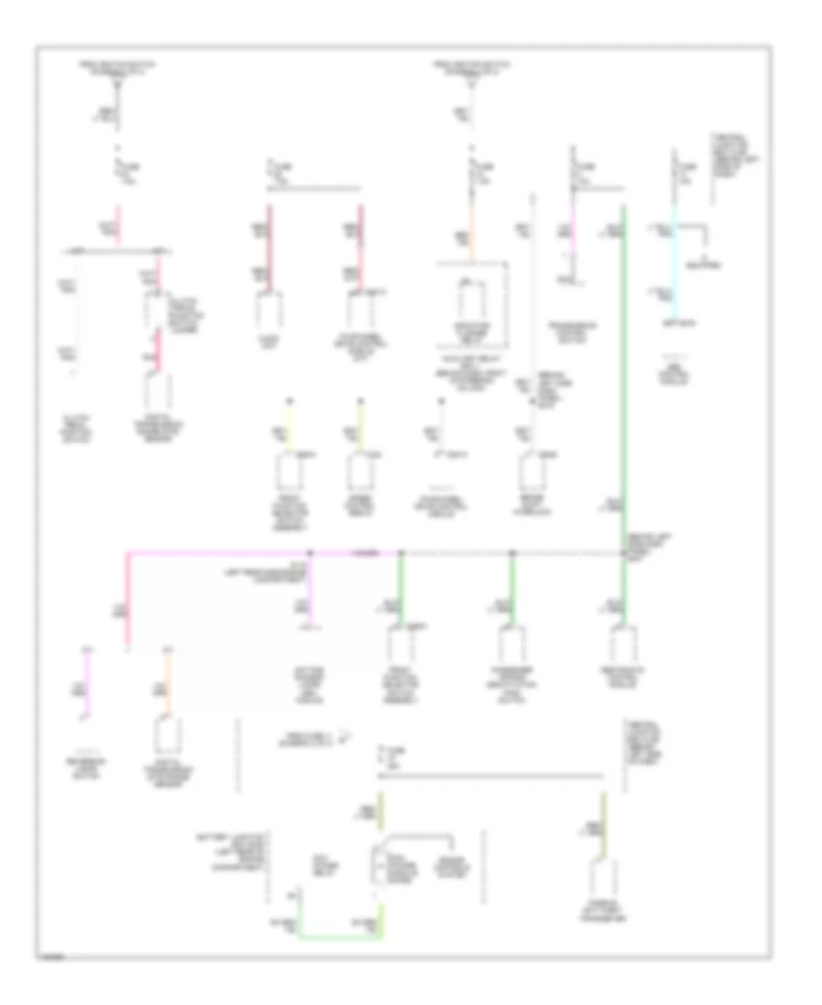
POWER DISTRIBUTION Power Distribution Wiring Diagram (1 of 3) for Ford Ranger 2002 List of elements for Power Distribution Wiring Diagram (1 of 3) for Ford Ranger 2002: 48 (behind left side dash panel) s238 (behind left side of dash) central junction box (cjb) (left rear of engine compartment) battery junction box (bjb) (right rocker panel) g201 A/c clutch relay Abs control module Audio unit Auxiliary relay box 1 (behind dash, right of steering column) Battery Battery saver relay Brake pedal position switch C102a C102b C135 C2031a C2031b C2100a C220c C274a C274b C281-a Central security module Data link connector (dlc) Deactivator switch Exterior rear view mirror switch Four-wheel drive control module Front cigar lighter Fuse 10a Fuse 15a Fuse 20a Fuse 50a Fuse 5a Fuse 7.5a G201 (right rocker panel) Generator Generic electronic module (gem) Horn relay Indicator flasher relay Instrument cluster Power point Powertrain control module (pcm) Red Restraints control module S203 S205 (behind center dash panel) Starter motor To fuse 23 (diagram 2 of 3) Trailer tow relay Power Distribution Wiring Diagram (2 of 3) for Ford Ranger 2002 List of elements for Power Distribution Wiring Diagram (2 of 3) for Ford Ranger 2002: 61 (behind left side dash panel) s218 (behind left side dash panel) s226 (left rear of engine compartment) battery junction box (bjb) (left rear side engine compartment) s112 (not used) Abs control module Acc Audio unit Auxiliary relay box 1 (behind dash, right of steering column) Battery junction box (bjb) (left rear of engine compartment) Blower motor relay C135 C202b C2100a C220a C220b C220c C274a C274b C281a C281b Central junction box (cjb) (behind left side of dash) Central security module Daytime running lamps (drl) module Engine cooling fan relay Fog lamp relay Four wheel drive control module Four-wheel drive control module From fuse 30 a (diagram 1 of 3) Fuel pump relay Fuel tank unit (w/flex fuel) Fuse 15a Fuse 20a Fuse 30a Fuse 40a Fuse 50a Fuse 7.5a Generic electronic module (gem) Ignition switch Instrument cluster Lock Lock off Main light switch Multifunction switch Off Pcm power relay Pnk Red Run S228 (on steering column) Sta Start Starter relay To fuse 10, 7.5a (diagram 3 of 3) To fuse 24, 7.5a (diagram 3 of 3) To fuse f2.19 (diagram 3 of 3) Window safety relay Windshield washer relay Windshield wiper motor Wiper high/low relay Wiper run/park relay Power Distribution Wiring Diagram (3 of 3) for Ford Ranger 2002 List of elements for Power Distribution Wiring Diagram (3 of 3) for Ford Ranger 2002: 42 (behind left side dash panel) s216 (behind left side dash panel) s237 A/t Abs control module Audio unit Auxiliary relay box 1 (behind dash, right of steering column) Battery junction box (bjb) (left rear of engine compartment) Brake shift interlock C122 C135 C2008 C281a C294a Central junction box (cjb) (behind left side of dash) Clutch pedal position switch Clutch triple function switch jumper Daytime running lamps (drl) module Digital transmission (dtr) range sensor Digital transmission range (dtr) sensor Engine controls system Four-wheel drive control module Four-wheel drive control module (m/t) From fuse 11 (diagram 2 of 3) From ignition switch (diagram 2 of 3) Front function selector switch assembly Fuse 10a Fuse 25a Fuse 7.5a If equipped Indicator flasher relay M/t Nca Passenger air bag deactivation (pad) switch Passive anti-theft transceiver Pcm power module diode Pcm power relay Pnk Restraints control module Reversing lamps switch S115 (left rear side engine compartment) Speed control servo Transmission control switch
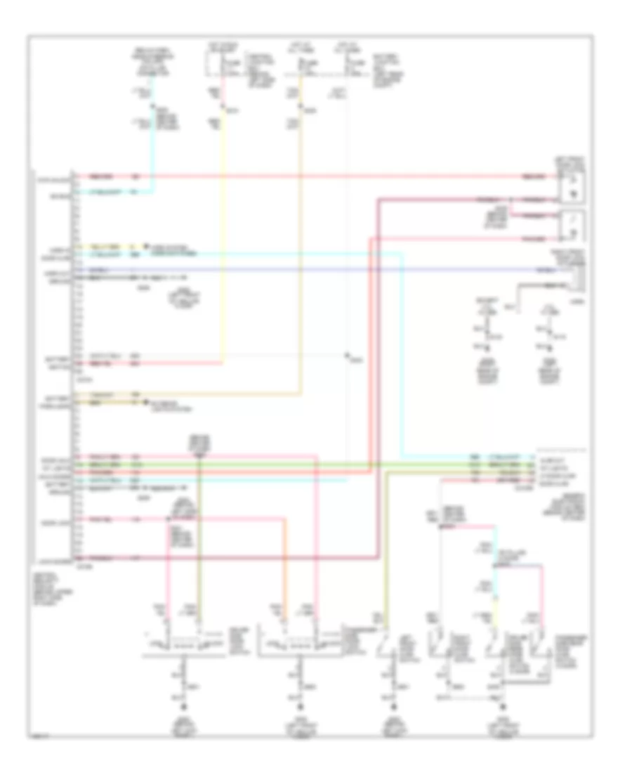
POWER DOOR LOCKS Power Door Lock Wiring Diagram for Ford Ranger 2002 List of elements for Power Door Lock Wiring Diagram for Ford Ranger 2002: 64 (behind center of dash) s234 (behind center of dash) s240 (below dash, near steering column) data link connector (except 2.3l w/ abs 2.3l w/ abs Ajar out Battery Battery junction box (left rear of engine compt) C2100b C274a C274b Central junction box (behind left side of dash) Central security module (behind upper right side of dash) Door ajar Door lock Door unlk Driver side door lock switch Driver side rear door ajar switch (4 door) Dvr unlock Exterior lights system Fuse 15a Fuse 20a Fuse 7.5a G103 (left rear of engine compt) G105 (right rear of engine compt) G200 (behind left kick panel) G204 (behind left side of dash) G205 (left front of vehilce floor) Generic electronic module (gem) (behind center of dash) Ground Horn Horn in Horn out Horn system (horn switches) Hot at all times Hot in run or start Ignition Int lights Iso bus Left front door ajar switch Left front door lock actuator Lf door ajar Lock Lock doors Parklamps Passenger side door lock switch Passenger side rear door ajar switch (4 door) Right front door ajar switch Right front door lock actuator S119 S123 S206 S208 (behind center of dash) S209 S218 S235 S239 (behind center of dash) S241 (behind center of dash) S242 S409 S501 S600 Unlk doors Unlock
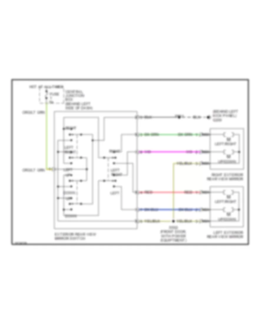
POWER MIRRORS Power Mirror Wiring Diagram for Ford Ranger 2002 List of elements for Power Mirror Wiring Diagram for Ford Ranger 2002: 17 (behind left kick panel) g200 Central junction box (behind left side of dash) Down Exterior rear view mirror switch Fuse 5a Hot at all times Left Left exterior rear view mirror Left right Left/right Nca Red Right Right exterior rear view mirror S501 S502 (front door, with power equiptment) Up/down
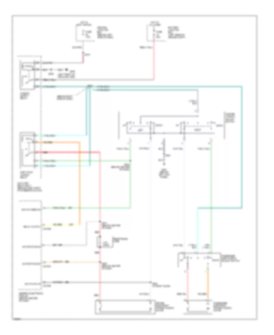
POWER WINDOWS Power Window Wiring Diagram for Ford Ranger 2002 List of elements for Power Window Wiring Diagram for Ford Ranger 2002: 38 (behind right side of dash) (left front of vehicle floor) .015 ohms Auxiliary relay box 1 (behind dash, right of steering column) Battery junction box (left rear of engine compt) C2100a C2100b Central junction box (behind left side of dash) Down Driver side front power window motor Fuse 20a Fuse 7.5a G200 (behind left kick panel) G205 Generic electronic module (behind center of dash) Hot at all times Hot in accy or run Left Master window adjust switch Motor fd down One touch window relay Passenger side front power window motor Passenger side window adjust switch Red Relay output Resistence wire Right S202 (behind center of dash) S204 (behind center of dash) S206 S210 (behind center of dash) S212 S219 S500 (in front door) S501 Switch fd up Switch feed dn Window safety relay
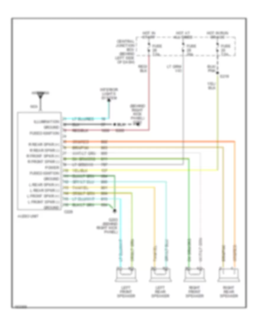
RADIO Radio Wiring Diagrams for Ford Ranger 2002 List of elements for Radio Wiring Diagrams for Ford Ranger 2002: 31 (behind right kick panel) g201 Antenna Audio unit C228 Central junction box (behind left side of dash) Fuse 20a Fuse 7.5a Fused ignition G203 (behind right kick panel) Ground Hot at all times Hot in run or acc Hot in start Illumination Interior lights system L front spkr (+) L front spkr (-) L rear spkr (+) L rear spkr (-) Left front speaker Left rear speaker Nca Power R front spkr (+) R front spkr (-) R rear spkr (+) R rear spkr (-) Right front speaker Right rear speaker S203 S219
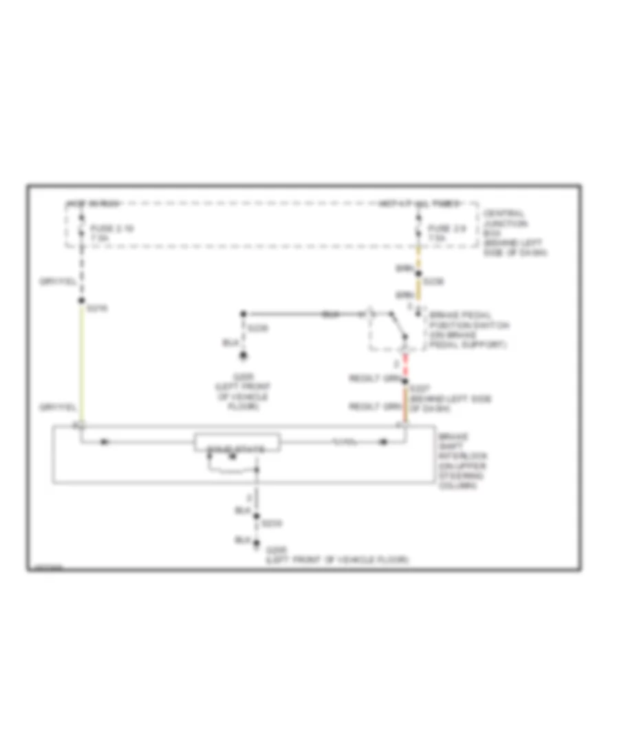
SHIFT INTERLOCKS Shift Interlock Wiring Diagram for Ford Ranger 2002 List of elements for Shift Interlock Wiring Diagram for Ford Ranger 2002: 13 Brake pedal position switch (on brake pedal support) Brake shift interlock (on upper steering column) Central junction box (behind left side of dash) Fuse 2.10 7.5a Fuse 2.9 7.5a G205 (left front of vehicle floor) Hot at all times Hot in run S216 S227 (behind left side of dash) S236 S238 Solid state
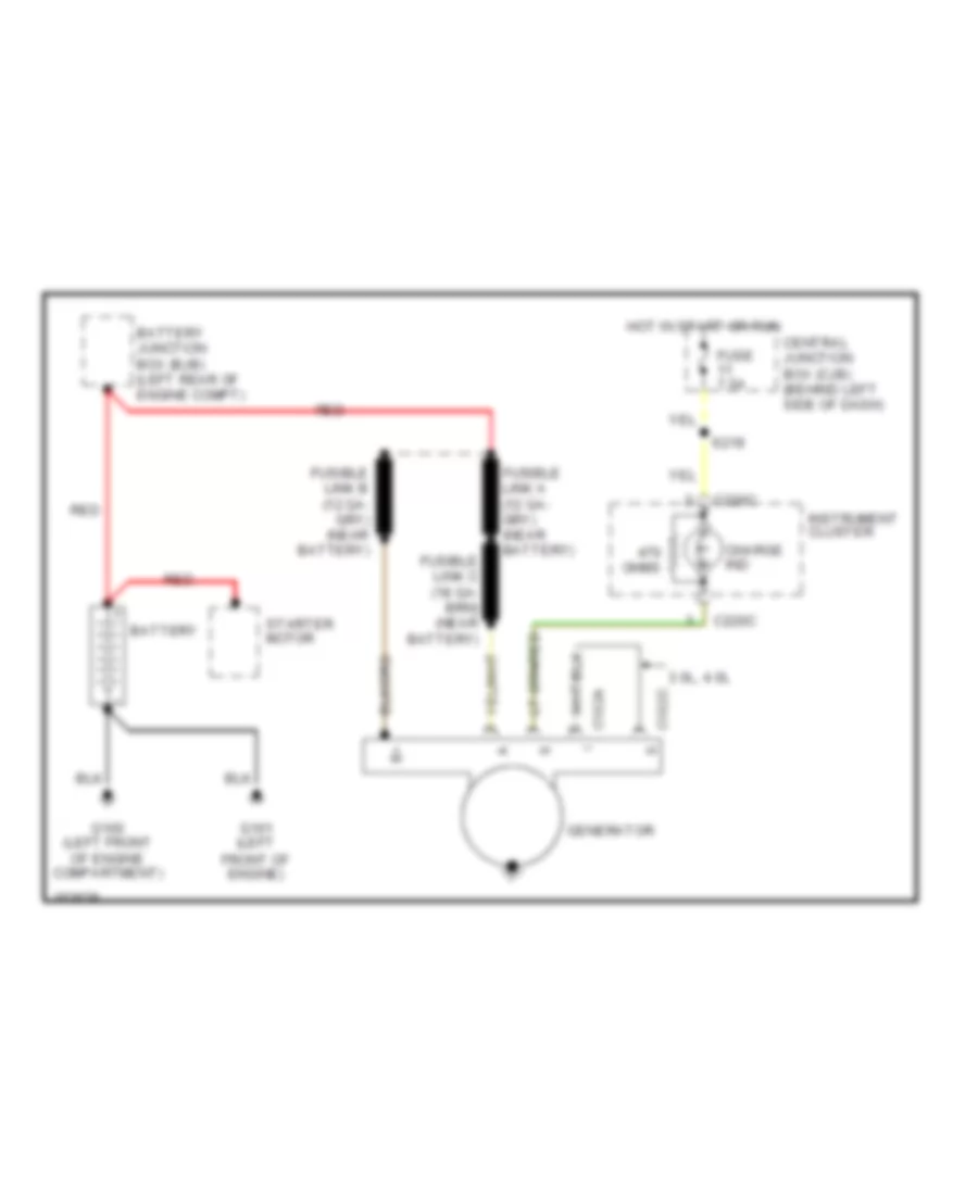
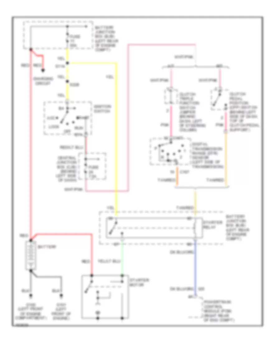
STARTING/CHARGING Charging Wiring Diagram for Ford Ranger 2002 List of elements for Charging Wiring Diagram for Ford Ranger 2002: 18 3.0l, 4.0l Battery Battery junction box (bjb) (left rear of engine compt) C102a C102c C220c Central junction box (cjb) (behind left side of dash) Charge ind Fuse 7.5a G100 (left front of engine compartment) G101 (left front of engine) Generator Hot in start or run Instrument cluster Ohms Red S218 Starter motor Starting Wiring Diagram for Ford Ranger 2002 List of elements for Starting Wiring Diagram for Ford Ranger 2002: 29 A/t Acc Battery Battery junction box (bjb) (left rear of engine compt) C167 Central junction box (cjb) (behind left side of dash) Charging circuit Clutch pedal position (cpp) switch (behind left side of dash, top of clutch pedal support) Clutch triple function switch jumper (behind dash, left of steering column) Digital transmission range (dtr) sensor (left side of transmission) Fuse 50a Fuse 7.5a G100 (left front of engine compartment) G101 (left front of engine) Ignition switch Lock M/t Off Pnk Powertrain control module (pcm) (right rear of eng compt) Red Run S114 S228 Sta Start Starter motor Starter relay Tan/red
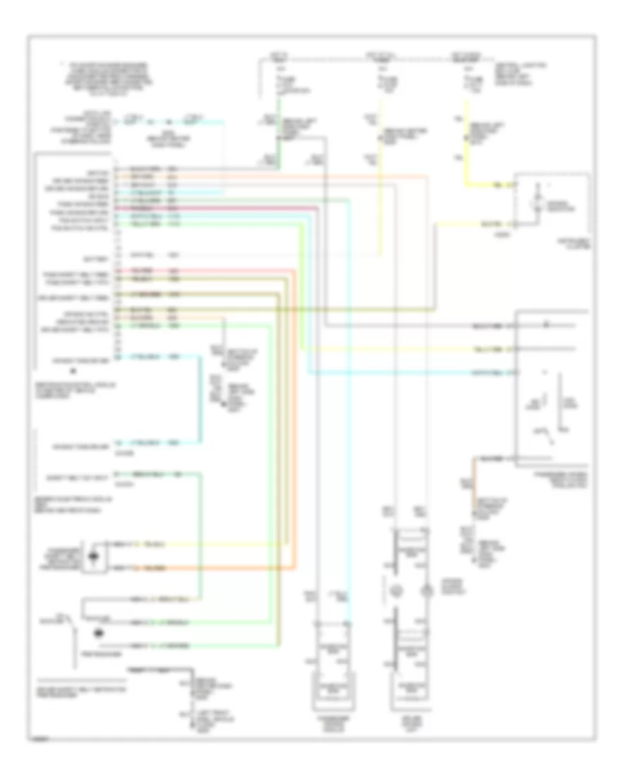
SUPPLEMENTAL RESTRAINTS Supplemental Restraint Wiring Diagram for Ford Ranger 2002 List of elements for Supplemental Restraint Wiring Diagram for Ford Ranger 2002: 54 (behind center dash panel) s205 (behind center dash panel) s206 (behind left side dash panel) g204 (behind left side dash panel) s218 (behind left side dash panel) s237 (bottom of steering column) s209 (left front side, vehicle floor) g205 Air bag ind ctrl Air bag indicator Air bag sliding contact Air bag tone driver Battery Buckled C2100a C2100b C220c Central junction box (cjb) (behind left side of dash) Data link connector (dlc) (partial) (fastened to bottom of dash, near steering column) Dedicated ground Driver air bag feed Driver air bag return Driver air bag unit Driver safety belt feed Driver safety belt retractor pretensioner Driver safety belt rtn Fuse f2.11 7.5a Fuse f2.2 10a or 20a Fuse f2.26 10a Generic electronic module (gem) (behind center of dash) Hot at all times Hot in run Hot in run or start Ignition Instrument cluster Iso bus Nca Off Ohms Pad switch ind ctrl Pad switch input Pass air bag feed Pass air bag return Pass safety belt feed Pass safety belt rtn Passenger air bag deactivation (pad) switch Passenger air bag module Passenger safety belt retractor pretensioner Pin shorting bars engaged when module connector is disconnected from harness: (shorting bars are connected between following pins: 3-4, 6-7 & 20-21) Pretensioner Restraints control module (in center of vehicle, under dash) S208 (behind center dash panel) Safety belt sw input Shorting bar Un- buckled
TRANSMISSION
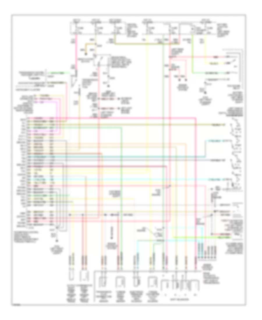
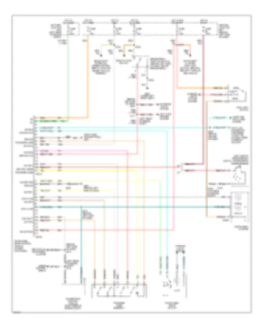
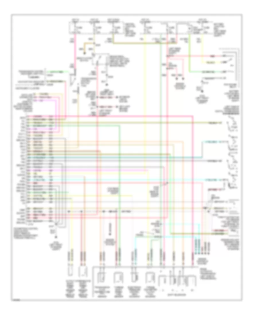
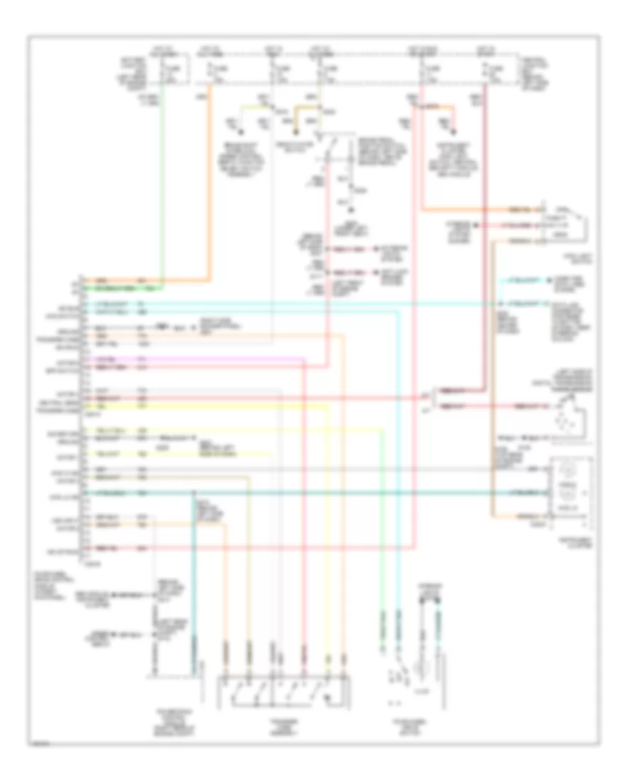
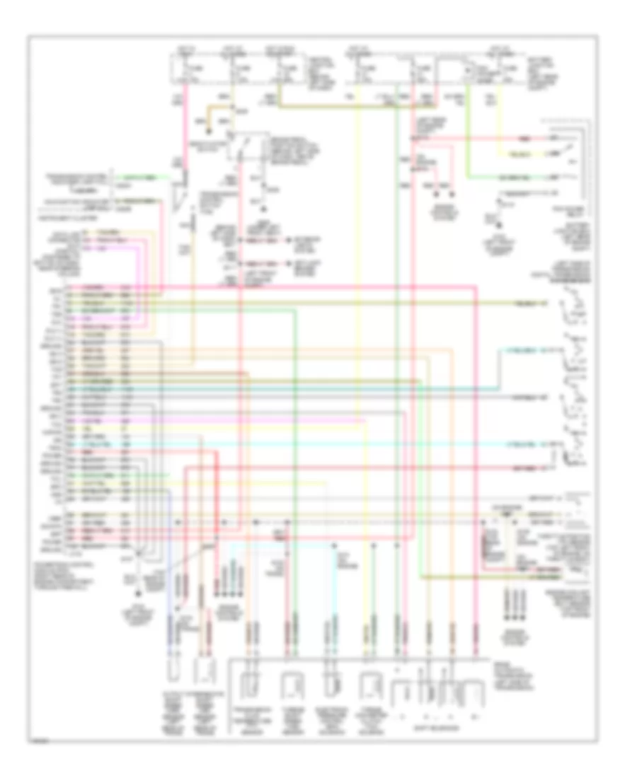
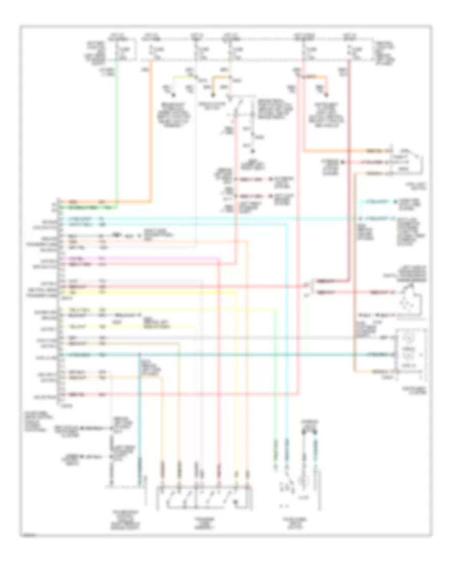
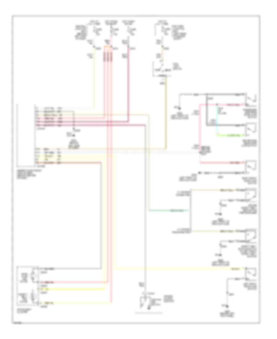
2.3L 2.3L, A/T Wiring Diagram for Ford Ranger 2002 List of elements for 2.3L, A/T Wiring Diagram for Ford Ranger 2002: 89 (behind left side of dash) s227 (dlc) (partial) (fastened to bottom of dash, near steering column) (left front of engine compt) (left rear of engine compt) s113 (left side of transmission) digital transmission range sensor (on engine) (on engine) s149 (top rear of engine compt) 5r44e automatic transmission (left side of transmission) Anti-lock brakes system Battery junction box (left rear of engine compt) Bpp Brake pedal position switch (behind left side of dash, above brake pedal) C175 C220a C220b Central junction box (behind left side of dash) Cht Cylinder head temperature (cht) sensor (right side of cylinder head) Data link connector Deactivator switch Dlc Dlc (+) Dlc (-) Electronic pressure control (epc) solenoid Engine controls system Epc Exterior lights system Fuse 10a Fuse 20a Fuse 25a Fuse 30a Fuse 7.5a G104 (left front of engine compt) G205 (under left front seat) Ground Hot at all times Hot in run Hot in run or start Instrument cluster Intermediate shaft speed (iss) sensor (left rear of trans) Iss Kapwr Malfunction indicator lamp (mil) Mil Nca O/d off Oss Output shaft speed (oss) sensor (left rear of trans) Pcm power diode Pcm power relay Power Powertrain control module (pcm) (right rear of engine compartment, through firewall) R p Red S107 S117 S118 S137 S143 S150 (on engine) S151 (on engine) S152 (on engine) S153 S154 S236 S238 Shift solenoids Sig rtn Ss a Ss b Ss c Ss d Tcc Tcil Tcs Tft Throttle position (tp) sensor (top left front of engine, on throttle body) Torque converter clutch (tcc) solenoid Tr1 Tr2 Tr3a Tr4 Transmission control indicator lamp (tcil) Transmission control switch (tcs) Transmission fluid temperature (tft) sensor Tss Turbine shaft speed (tss) sensor Vref 4WD Wiring Diagram for Ford Ranger 2002 List of elements for 4WD Wiring Diagram for Ford Ranger 2002: 74 (behind left side of dash) s213 (behind left side of dash) s227 (left front of engine compt) (left side of transmission) digital transmission range sensor (right side rocker panel) g201 4wd hi 4wd hi ind 4wd lo 4wd lo ind 4wd switch A/t Anti-lock brakes system Battery junction box (left rear of engine compt) Bpp switch Brake pedal position switch (behind left side of dash, above brake pedal) Brake shift interlock, speed control servo, function select switch assembly C175 C220a C281a C281b Central junction box (behind left side of dash) Computer data lines system Data link connector (fastened to bottom of dash, near steering column) Deactivator switch Exterior lights system Four-wheel drive control module (in right kick panel) Four-wheel drive switch Fuse 15a Fuse 20a Fuse 7.5a G106 (top rear of engine compt) G204 (behind left side of dash) G205 (under left front seat) Gem module, instrument cluster Ground Head Hot at all times Hot in run Hot in run or start Hot in start Ign (run) Ign (st/run) Illum Instrument cluster Instrument cluster, main light switch, central security module, gem module Interior lights system Interior lights system (dimmer) Iso bus M/t Main light switch Motor 1 Motor 2 Motor 3 Motor 4 Motor 5 Neutral sens Off Park Powertrain control module (right rear of engine compt) S117 S145 S203 S208 (behind center of dash) S209 S215 (behind left side of dash) S216 S218 S236 S238 Sig return Speed control servo Transfer case Transfer case assembly Vss input
3.0L 3.0L, A/T Wiring Diagram for Ford Ranger 2002 List of elements for 3.0L, A/T Wiring Diagram for Ford Ranger 2002: 89 (behind left side of dash) s227 (dlc) (partial) (fastened to bottom of dash, near steering column) (left front of engine compt) (left rear of engine compt) s113 (left side of transmission) digital transmission range sensor (on engine) (on engine) s104 (on engine) s106 (on trans) (top rear of engine compt) 5r44e automatic transmission (left side of transmission) Anti-lock brakes system Battery junction box (left rear of engine compt) Bpp Brake pedal position switch (behind left side of dash, above brake pedal) C175 C220a C220b Central junction box (behind left side of dash) Data link connector Deactivator switch Dlc Dlc (+) Dlc (-) Ect Electronic pressure control (epc) solenoid Engine controls system Engine coolant temperature (ect) sensor (top front of engine) Epc Exterior lights system Fuse 10a Fuse 20a Fuse 25a Fuse 30a Fuse 7.5a G104 (left front of engine compt) G205 (under left front seat) Ground Hot at all times Hot in run Hot in run or start Instrument cluster Intermediate shaft speed (iss) sensor (left rear of trans) Iss Kapwr Malfunction indicator lamp (mil) Mil Nca O/d off Oss Output shaft speed (oss) sensor (left rear of trans) Pcm power diode Pcm power relay Power Powertrain control module (pcm) (right rear of engine compartment, through firewall) R p Red S100 S107 S117 S118 S129 (top rear of engine compt) S137 S139 S143 S236 S238 Shift solenoids Sig rtn Ss a Ss b Ss c Ss d Tcc Tcil Tcs Tft Throttle position (tp) sensor (top left front of engine, on throttle body) Torque converter clutch (tcc) solenoid Tr1 Tr2 Tr3a Tr4 Transmission control indicator lamp (tcil) Transmission control switch (tcs) Transmission fluid temperature (tft) sensor Tss Turbine shaft speed (tss) sensor Vref 4WD Wiring Diagram for Ford Ranger 2002 List of elements for 4WD Wiring Diagram for Ford Ranger 2002: 74 (behind left side of dash) s213 (behind left side of dash) s227 (left front of engine compt) (left side of transmission) digital transmission range sensor (right side rocker panel) g201 4wd hi 4wd hi ind 4wd lo 4wd lo ind 4wd switch A/t Anti-lock brakes system Battery junction box (left rear of engine compt) Bpp switch Brake pedal position switch (behind left side of dash, above brake pedal) Brake shift interlock, speed control servo, function select switch assembly C175 C220a C281a C281b Central junction box (behind left side of dash) Computer data lines system Data link connector (fastened to bottom of dash, near steering column) Deactivator switch Exterior lights system Four-wheel drive control module (in right kick panel) Four-wheel drive switch Fuse 15a Fuse 20a Fuse 7.5a G106 (top rear of engine compt) G204 (behind left side of dash) G205 (under left front seat) Gem module, instrument cluster Ground Head Hot at all times Hot in run Hot in run or start Hot in start Ign (run) Ign (st/run) Illum Instrument cluster Instrument cluster, main light switch, central security module, gem module Interior lights system Interior lights system (dimmer) Iso bus M/t Main light switch Motor 1 Motor 2 Motor 3 Motor 4 Motor 5 Neutral sens Off Park Powertrain control module (right rear of engine compt) S117 S145 S203 S208 (behind center of dash) S209 S215 (behind left side of dash) S216 S218 S236 S238 Sig return Speed control servo Transfer case Transfer case assembly Vss input
4.0L 4.0L, A/T Wiring Diagram for Ford Ranger 2002 List of elements for 4.0L, A/T Wiring Diagram for Ford Ranger 2002: 88 (behind left side of dash) s227 (dlc) (partial) (fastened to bottom of dash, near steering column) (left front of engine compt) (left rear of engine compt) s113 (left side of transmission) digital transmission range sensor (on engine) s104 (on engine) s133 (on engine) s137 (top rear of engine compt) 5r44e automatic transmission (left side of transmission) Anti-lock brakes system Battery junction box (left rear of engine compt) Bpp Brake pedal position switch (behind left side of dash, above brake pedal) C175 C220a C220b Central junction box (behind left side of dash) Data link connector Deactivator switch Dlc Dlc (+) Dlc (-) Ect Electronic pressure control (epc) solenoid Engine controls system Engine coolant temperature (ect) sensor (top front of engine) Epc Exterior lights system Fuse 10a Fuse 20a Fuse 25a Fuse 30a Fuse 7.5a G104 (left front of engine compt) G205 (under left front seat) Ground Hot at all times Hot in run Hot in run or start Instrument cluster Intermediate shaft speed (iss) sensor (left rear of trans) Iss Kapwr Malfunction indicator lamp (mil) Mil Nca O/d off Oss Output shaft speed (oss) sensor (left rear of trans) Pcm power diode Pcm power relay Power Powertrain control module (pcm) (right rear of engine compartment, through firewall) R p Red S107 S117 S118 S129 S135 (on engine) S140 (on trans) S141 (on engine) S144 (on trans) S236 S238 Shift solenoids Sig rtn Ss a Ss b Ss c Ss d Tcc Tcil Tcs Tft Throttle position (tp) sensor (top left front of engine, on throttle body) Torque converter clutch (tcc) solenoid Tr1 Tr2 Tr3a Tr4 Transmission control indicator lamp (tcil) Transmission control switch (tcs) Transmission fluid temperature (tft) sensor Tss Turbine shaft speed (tss) sensor Vref 4WD Wiring Diagram for Ford Ranger 2002 List of elements for 4WD Wiring Diagram for Ford Ranger 2002: 74 (behind left side of dash) s213 (behind left side of dash) s227 (left front of engine compt) (left side of transmission) digital transmission range sensor (right side rocker panel) g201 4wd hi 4wd hi ind 4wd lo 4wd lo ind 4wd switch A/t Anti-lock brakes system Battery junction box (left rear of engine compt) Bpp switch Brake pedal position switch (behind left side of dash, above brake pedal) Brake shift interlock, speed control servo, function select switch assembly C175 C220a C281a C281b Central junction box (behind left side of dash) Computer data lines system Data link connector (fastened to bottom of dash, near steering column) Deactivator switch Exterior lights system Four-wheel drive control module (in right kick panel) Four-wheel drive switch Fuse 15a Fuse 20a Fuse 7.5a G106 (top rear of engine compt) G204 (behind left side of dash) G205 (under left front seat) Gem module, instrument cluster Ground Head Hot at all times Hot in run Hot in run or start Hot in start Ign (run) Ign (st/run) Illum Instrument cluster Instrument cluster, main light switch, central security module, gem module Interior lights system Interior lights system (dimmer) Iso bus M/t Main light switch Motor 1 Motor 2 Motor 3 Motor 4 Motor 5 Neutral sens Off Park Powertrain control module (right rear of engine compt) S117 S145 S203 S208 (behind center of dash) S209 S215 (behind left side of dash) S216 S218 S236 S238 Sig return Speed control servo Transfer case Transfer case assembly Vss input
WARNING SYSTEMS Warning System Wiring Diagrams for Ford Ranger 2002 List of elements for Warning System Wiring Diagrams for Ford Ranger 2002: 46 Air bag sliding contact Battery junction box (left rear of engine compt) C2100a C2100b C218a C220a C220b C220c Central junction box (behind left side of dash) Door ajar indi- cator Driver safety belt retractor pretensioner Driver side rear door ajar switch Fuse 10a Fuse 15a Fuse 7.5a G200 (behind left kick panel) G204 (behind left side of dash) G205 (left front of vehicle floor) Generic electronic module (gem)/ (behind center of dash) Head Hot at all times Hot in run or acc Hot in run or start Ignition key switch Instrument cluster Left front door ajar switch Main light switch Nca Off Park Passenger side rear door ajar switch Right front door ajar switch S205 S206 S209 S218 S219 S235 S409 S410 ("b" pillar) S501 S600 Safety belt buckle switch (in left front safety belt buckle) Safety belt indi- cator W/ air bag connected W/ air bag disconnected
WIPER/WASHER Wiper/Washer Wiring Diagram for Ford Ranger 2002 List of elements for Wiper/Washer Wiring Diagram for Ford Ranger 2002: 45 1370k 1910k 249k 2670k 401k 402k 634k 955k 956k Battery junction box (left rear of engine compartment) C202b C2100a C2100b Central junction box (behind left side of dash) Circuit breaker Fuse 16 30a G103 (top center of left front fender apron) G105 (top center of right front fender apron) Generic electronic module/ central timer module (behind center of dash) Hot in acc or run Int Interval delay wash input Mode select switch input Multi- function switch Off Park Park sense Red Return Run Run/park relay control S109 (left rear of engine compt) S110 S112 S123 Tan/red Washer pump relay control Washer switch Windshield washer pump (in washer reservoir) Windshield washer relay Windshield wiper motor Wiper hi-lo relay Wiper high/low relay control Wiper run/ park relay Wiper switch