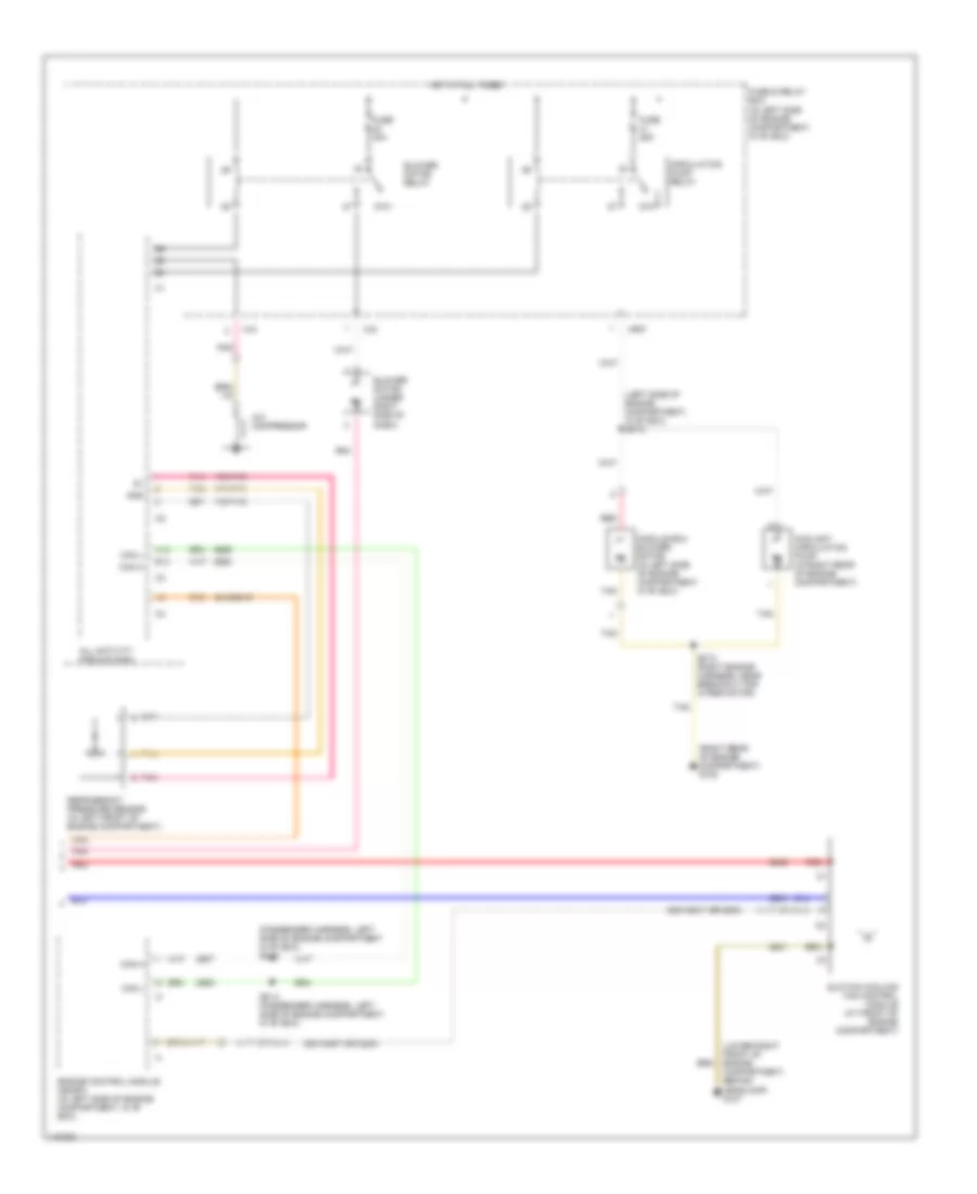
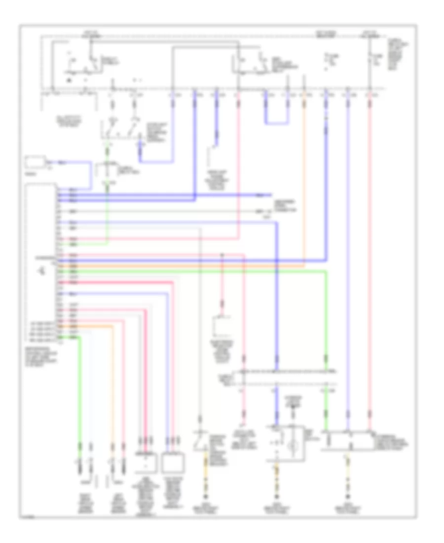
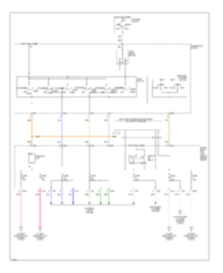
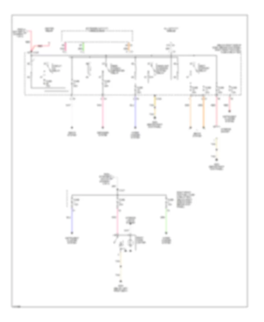
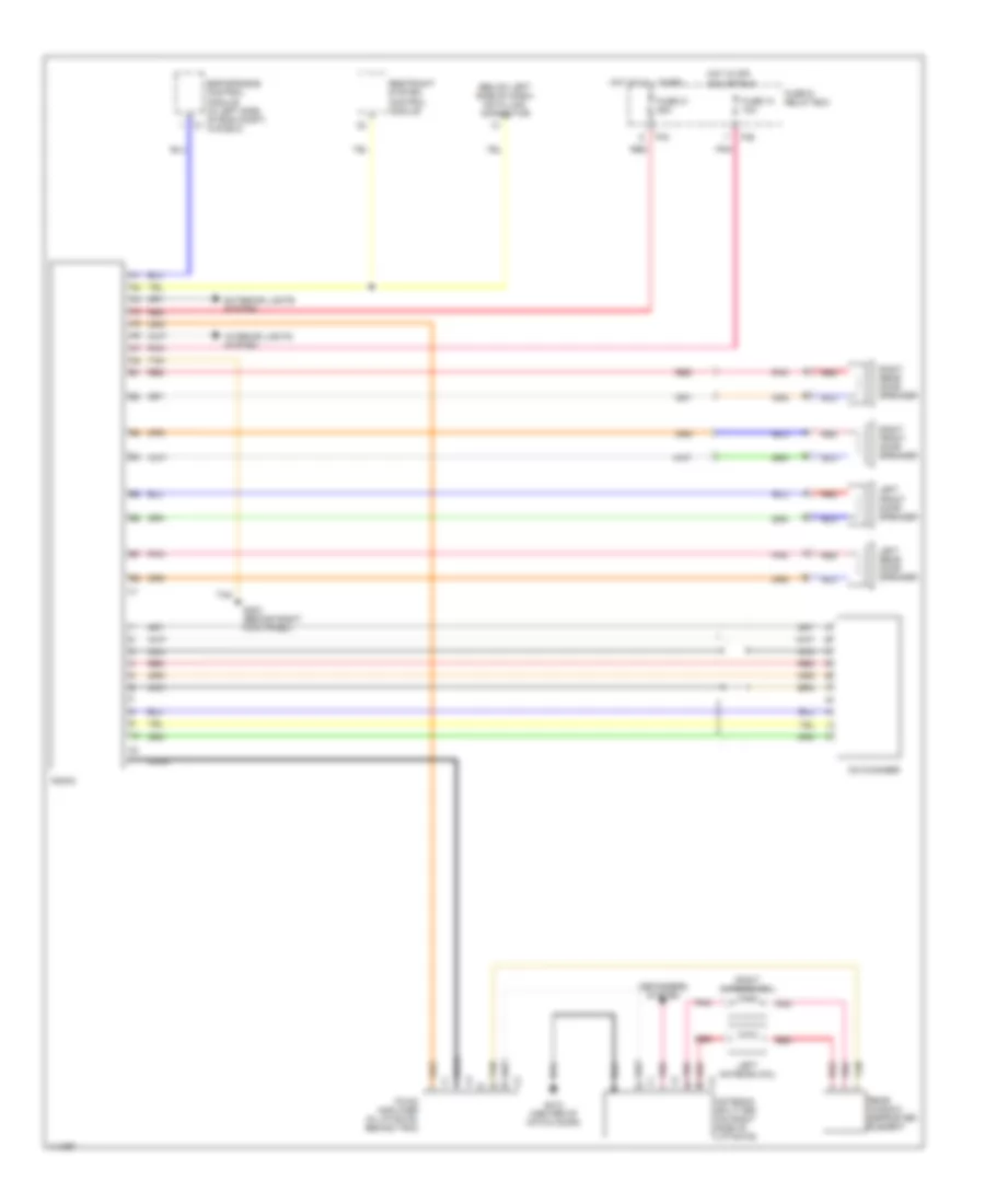
AIR CONDITIONING
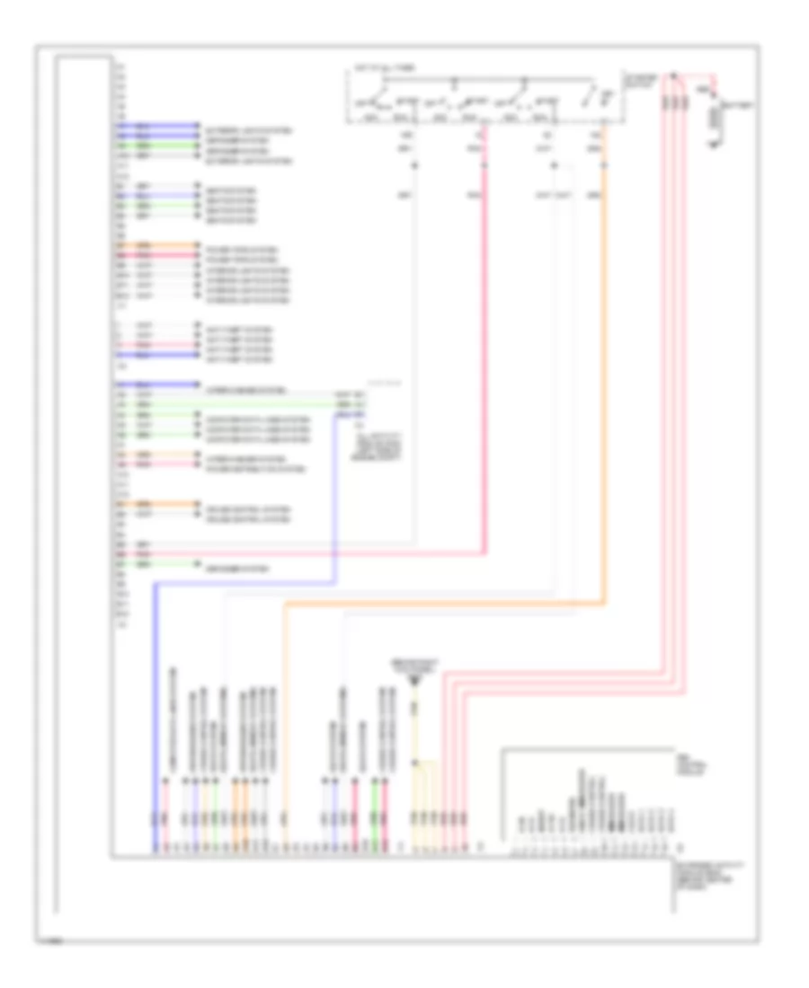
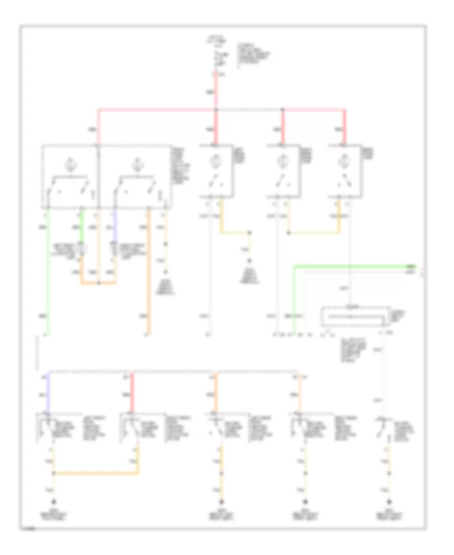
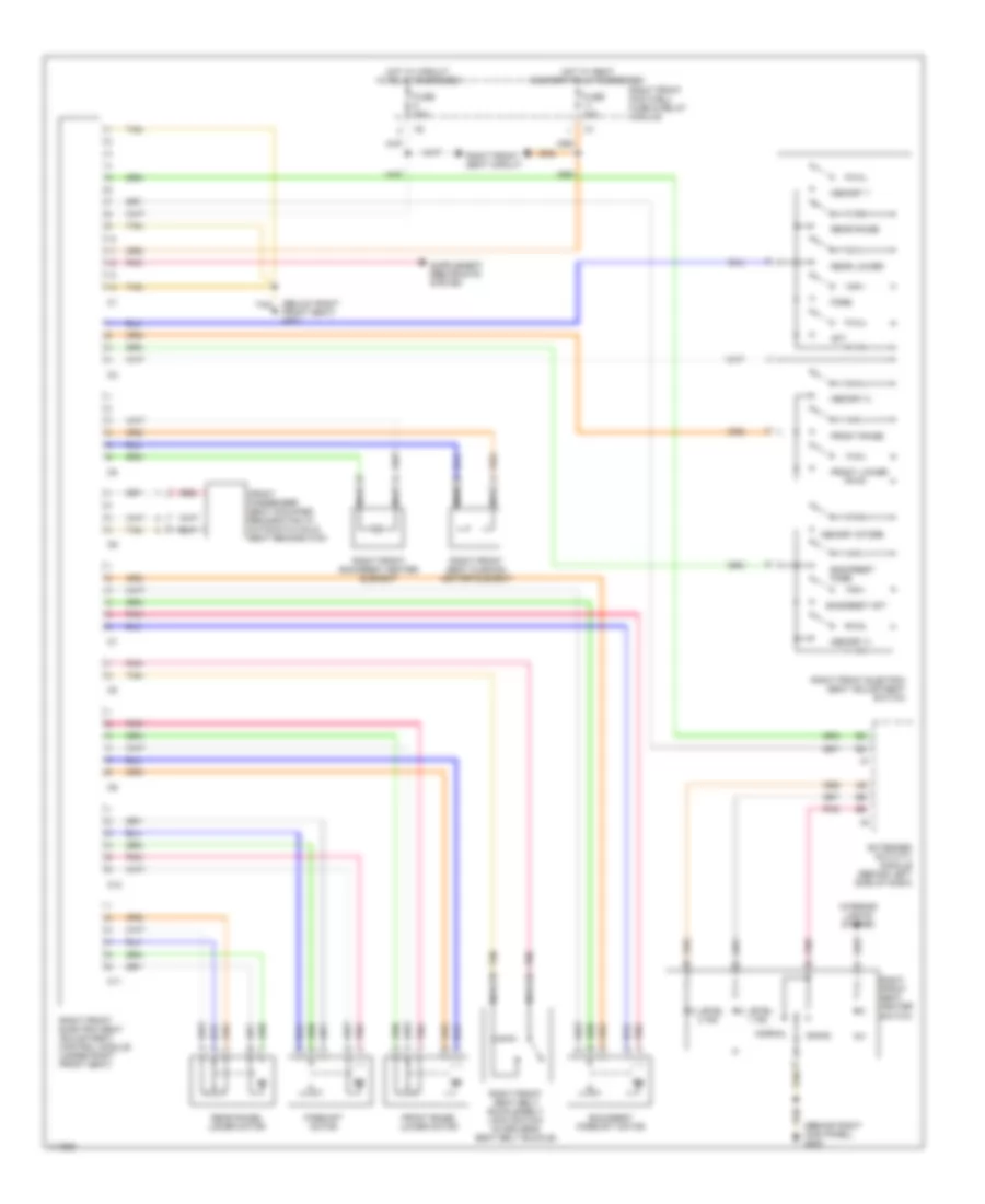
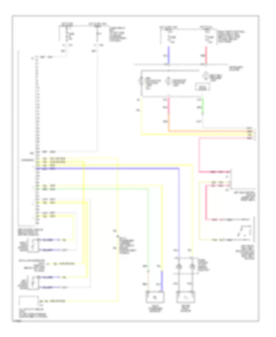
Manual A/C Wiring Diagram, with Coolant Fan Control Module (1 of 2) for Mercedes-Benz ML430 2000

List of elements for Manual A/C Wiring Diagram, with Coolant Fan Control Module (1 of 2) for Mercedes-Benz ML430 2000:
- (below passenger's side of cockpit, behind kick panel) g203
- (cockpit harness, center, in breakout for a/c control module) z50/29
- (cockpit harness, right side, near breakout for icing sensor) z50/4
- 2406/6406
- 2409/6409
- 2411/6411
- 2412/6412
- 2413/6413
- 2415/6415
- 2418/6418
- 2419/6419
- 2420/6420
- 2422/6422
- 2432/6432
- 2433/6433
- 2437/6437
- 2445/6445
- A/c on switch
- A/c pushbutton control module
- Blend air flap actuator motor (behind right side of dash)
- Blower motor preresistor group (under right side of dash, in blower assembly)
- Blower switch
- C/c
- Exhaust ventilator auxiliary fuse (right rear of engine compartment)
- Freeze protection temperature sensor (behind right side of dash, in evaporator)
- Fresh
- Fuse & relay box (in left side of engine compartment, in "e" box)
- Fuse 15a
- Fuse 70a
- Gnd
- Heater a/c switch
- High
- Hot at all times
- Hot in on or start
- Illumination
- In-car temperature sensor (behind center of dash)
- In-car temperature sensor aspirator blower (behind center of dash)
- Interior lights system
- Low
- Med 1
- Med 2
- Mr/e
- Mtr ctrl
- Nca
- Off
- Outside temperature sensor (behind lower right side of dash)
- Pnk
- Recirc
- Recirculated air flap element (behind right side of dash)
- Recirculated air switch
- Red
- Tan
- Temperature regulator
- Vref
- Z50/2 (cockpit harness, center, near breakout for a/c control module)
- Z50/3 (cockpit harness, near breakout for passenger harness to cockpit harness interconnect)
- Z50/30 (cockpit harness, center, near breakout for a/c control module)
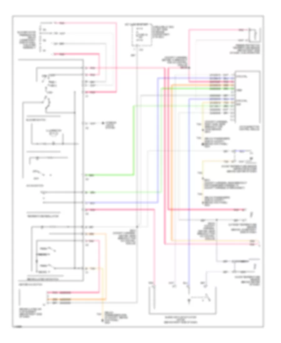
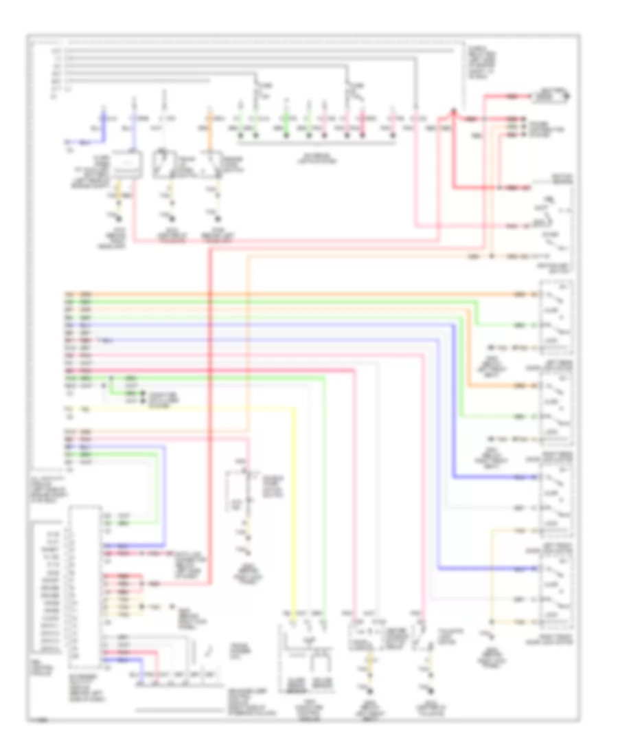
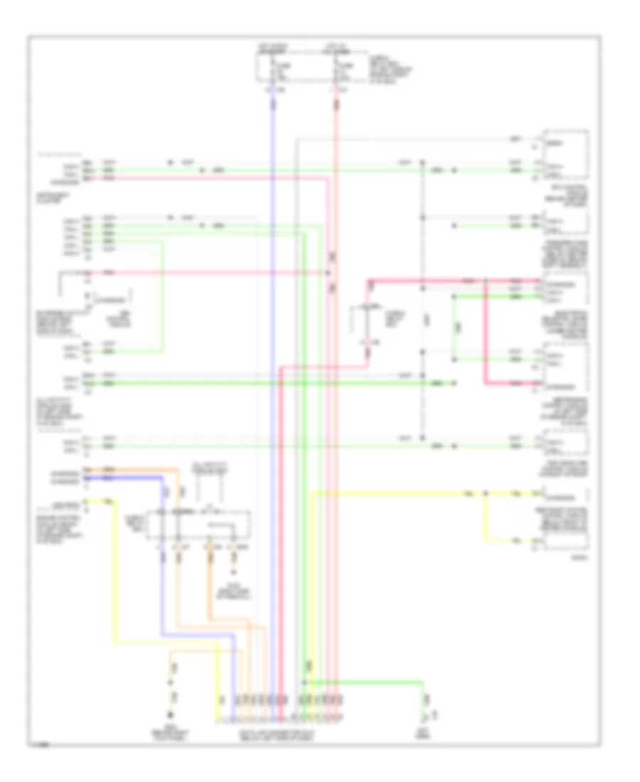
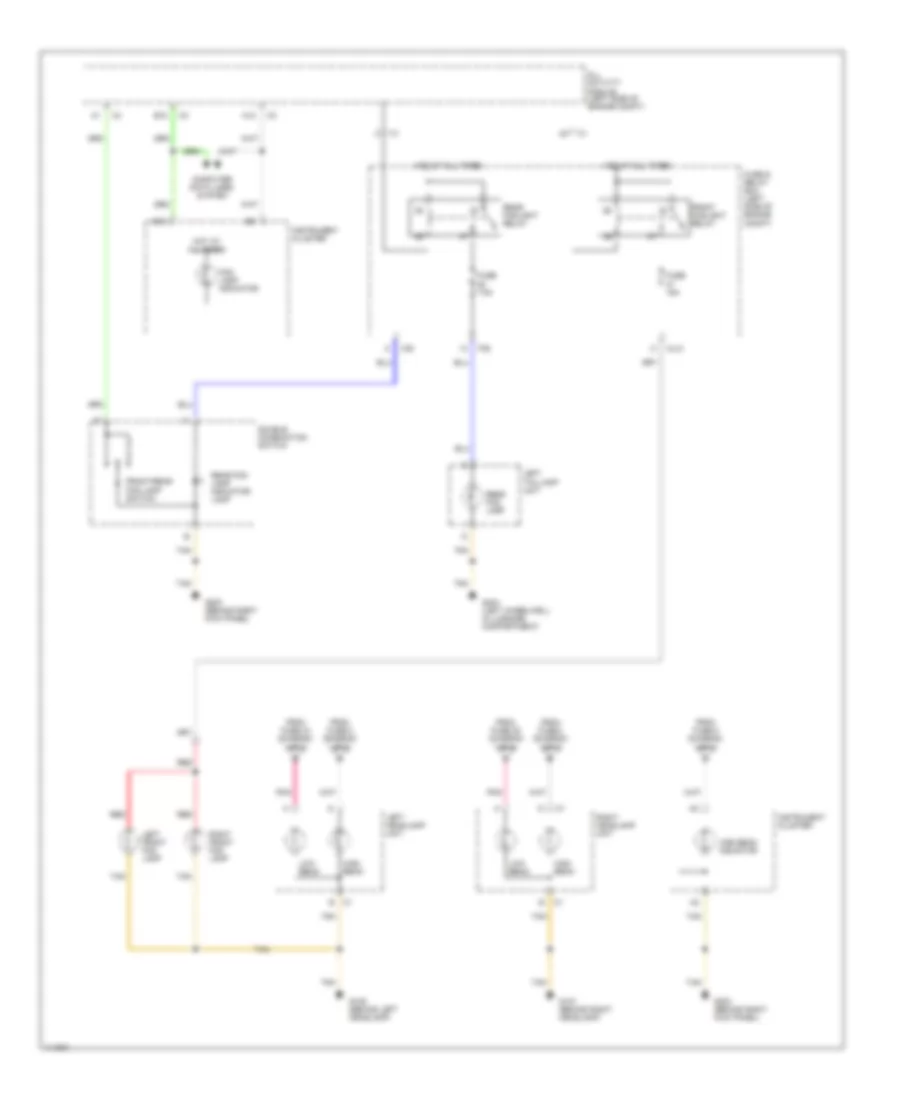
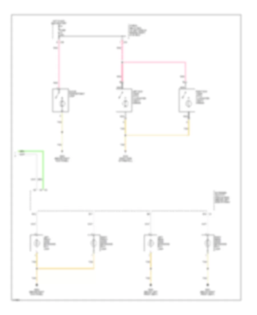
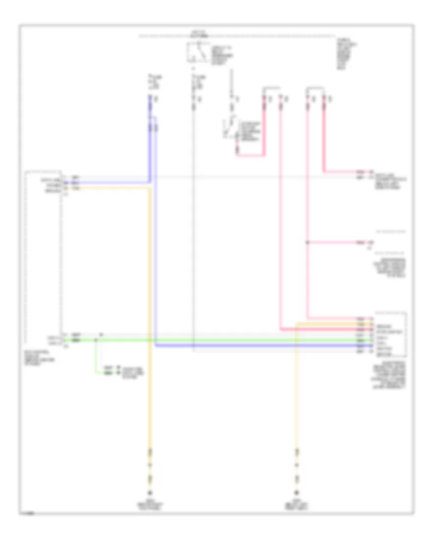
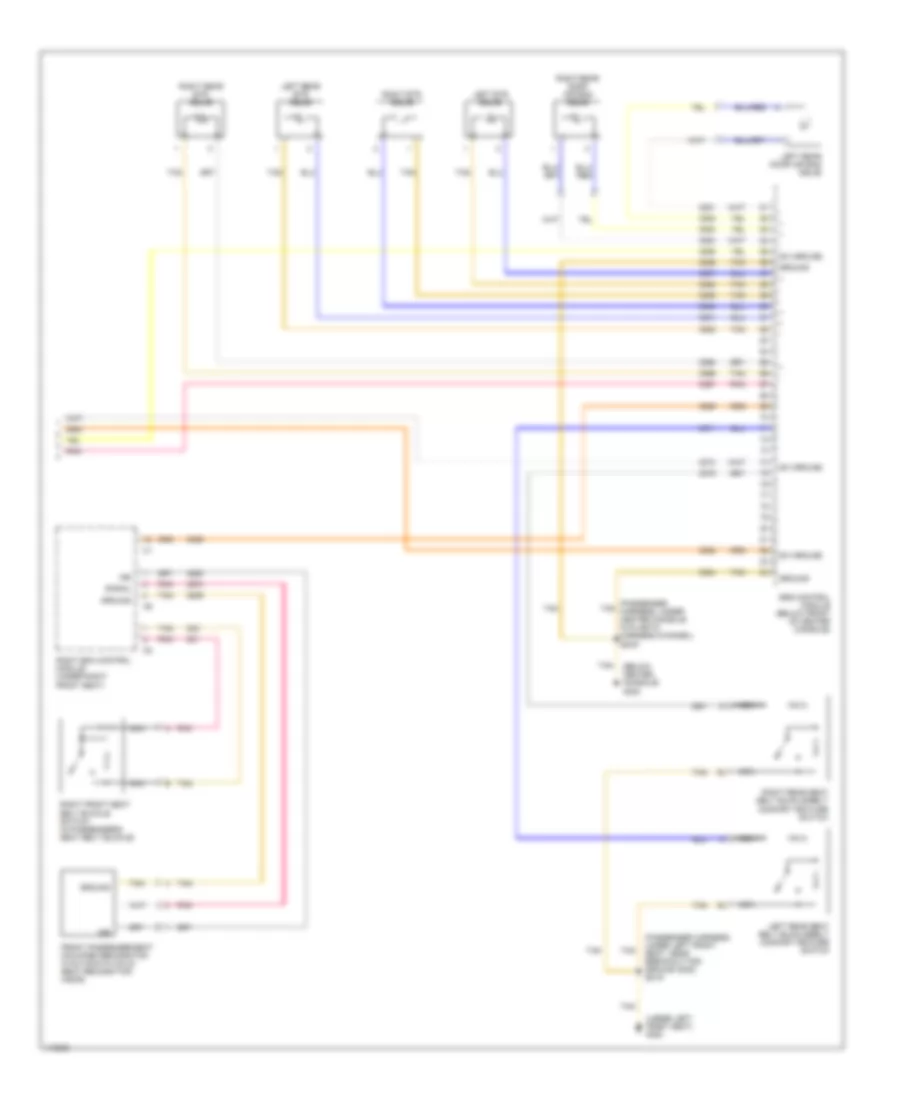
Manual A/C Wiring Diagram, with Coolant Fan Control Module (2 of 2) for Mercedes-Benz ML430 2000
List of elements for Manual A/C Wiring Diagram, with Coolant Fan Control Module (2 of 2) for Mercedes-Benz ML430 2000:
- (left side of engine compartment, in "e" box) z57-2
- (lower right front of engine compartment, behind headlamp) g107
- (passenger harness, left side of engine compartment in "e" box) z51/3
- (right rear of engine compartment) g105
- 170/7170
- 171/7171
- 172/7172
- 2081/8457 (or 2203)
- 2081/8547 (or 2203)
- 2415/6415
- 87a
- A/c compressor
- A12
- All activity module (aam)
- B12
- Blower motor (under right side of dash)
- Blower motor relay
- C/g
- Can h
- Can l
- Circulation pump relay
- Coolant circulation pump (in right rear of engine compartment)
- Engine control module (me-sfi) (in left side of engine compartment, in "e" box)
- Fuse & relay box (in left side of engine compartment, in "e" box)
- Fuse 25a
- Fuse 30a
- Gnd
- Hot at all times
- M/a
- Module box blower motor (in left side of engine compartment, in "e" box)
- Mr/f
- Pnk
- Red
- Refrigerant pressure sensor (in left front of engine compartment)
- Suction cooling fan control module (at front of engine compartment)
- Tan
- Z51/4 (passenger harness, left side of engine compartment, in "e" box)
- Z57/3 (right engine harness, near breakout for wiper motor)
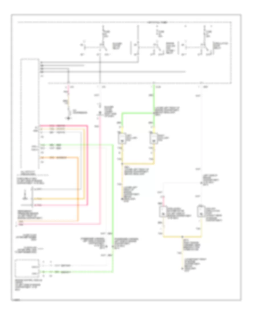
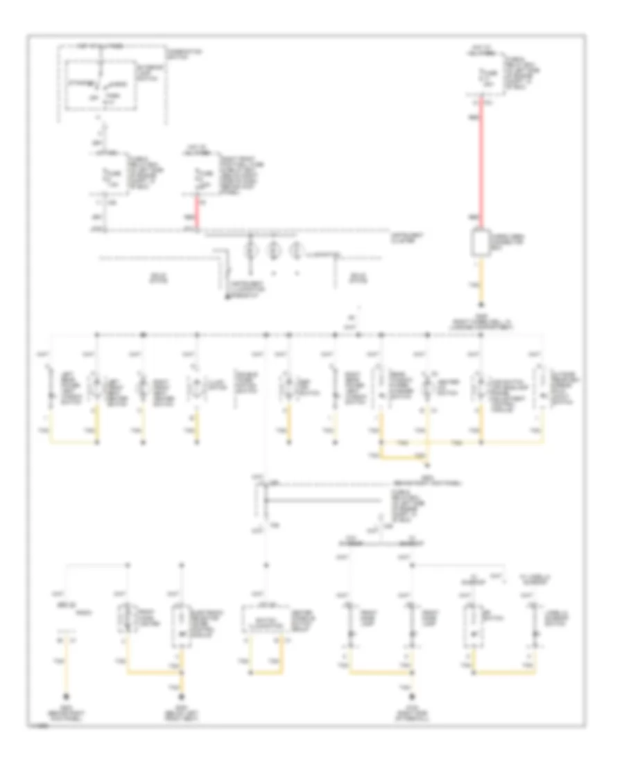
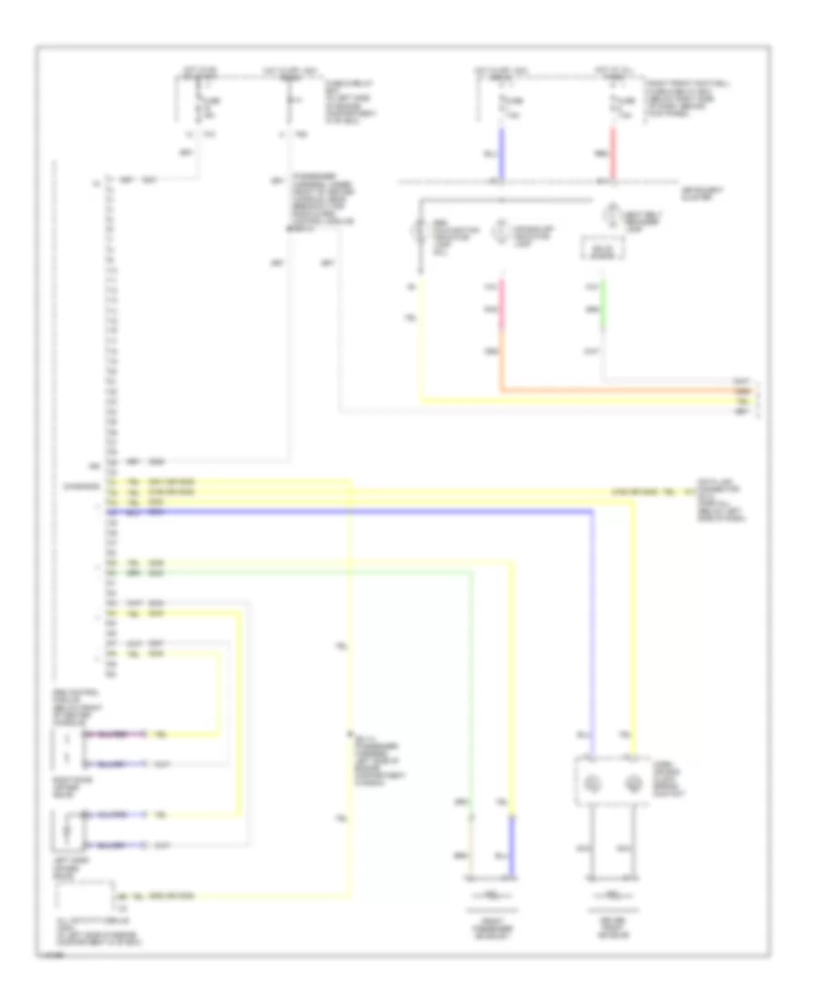
Manual A/C Wiring Diagram, without Coolant Fan Control Module (1 of 2) for Mercedes-Benz ML430 2000
List of elements for Manual A/C Wiring Diagram, without Coolant Fan Control Module (1 of 2) for Mercedes-Benz ML430 2000:
- (below passenger's side of cockpit, behind kick panel) g203
- (cockpit harness, center, in breakout for a/c control module) z50/29
- (cockpit harness, right side, near breakout for icing sensor) z50/4
- 2406/6406
- 2409/6409
- 2411/6411
- 2412/6412
- 2413/6413
- 2415/6415
- 2418/6418
- 2419/6419
- 2420/6420
- 2422/6422
- 2432/6432
- 2433/6433
- 2437/6437
- 2445/6445
- A/c on switch
- A/c pushbutton control module
- Blend air flap actuator motor (behind right side of dash)
- Blower motor preresistor group (under right side of dash, in blower assembly)
- Blower switch
- C/c
- Freeze protection temperature sensor (behind right side of dash, in evaporator)
- Fresh
- Fuse & relay box (in left side of engine compartment, in "e" box)
- Fuse 16 15a
- Gnd
- Heater a/c switch
- High
- Hot in on or start
- Illumination
- In-car temperature sensor (behind center of dash)
- In-car temperature sensor aspirator blower (behind center of dash)
- Interior lights system
- Low
- Med 1
- Med 2
- Mtr ctrl
- Nca
- Off
- Outside temperature sensor (behind lower right side of dash)
- Pnk
- Recirc
- Recirculated air flap element (behind right side of dash)
- Recirculated air switch
- Tan
- Temperature regulator
- Vref
- Z50/2 (cockpit harness, center, near breakout for a/c control module)
- Z50/3 (cockpit harness, near breakout for passenger harness to cockpit harness interconnect)
- Z50/30 (cockpit harness, center, near breakout for a/c control module)
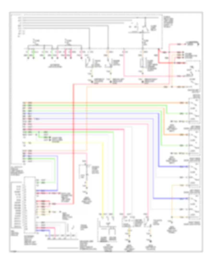
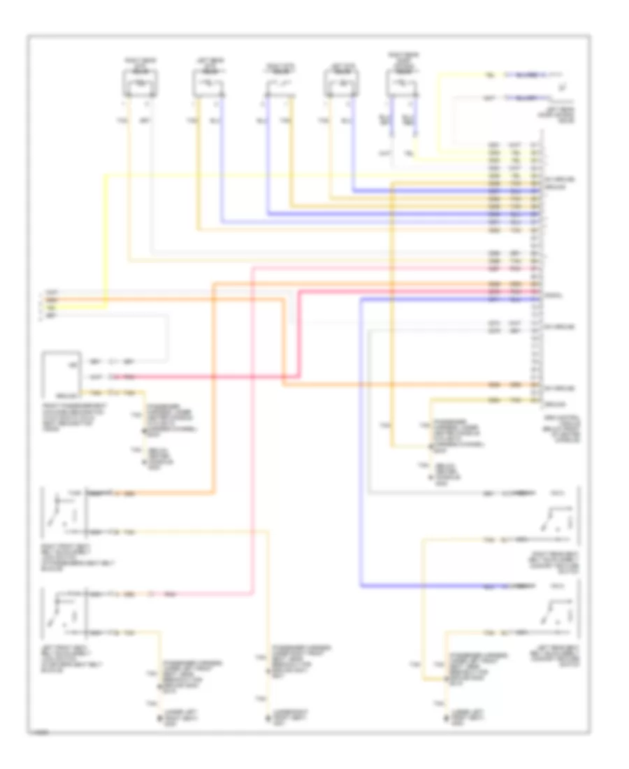
Manual A/C Wiring Diagram, without Coolant Fan Control Module (2 of 2) for Mercedes-Benz ML430 2000
List of elements for Manual A/C Wiring Diagram, without Coolant Fan Control Module (2 of 2) for Mercedes-Benz ML430 2000:
- (left side of engine compartment, in "e" box) z57-2
- (lower left front of engine compartment, behind headlamp) g106
- (lower left front of engine compartment, behind headlamp) z56/2
- (lower right front of engine compartment, behind headlamp) g107
- (passenger harness, left side of engine compartment, in "e" box) z51/3
- (passenger harness, left side of engine compartment, in "e" box) z51/4
- 170/7170
- 171/7171
- 172/7172
- 2415/6415
- 2607/3401
- 2608/3411
- 87a
- A/c compressor
- A12
- All activity module (aam)
- B12
- Blower motor (under right side of dash)
- Blower motor relay
- C/g
- Can h
- Can l
- Circulation pump relay
- Coolant circulation pump (in right rear of engine compartment)
- Engine control module (me-sfi) (in left side of engine compartment, in "e" box)
- Engine cooling fan stage 1 relay
- Fuse & relay box (in left side of engine compartment, in "e" box)
- Fuse 25a
- Fuse 30a
- Gnd
- Hot at all times
- Left auxiliary fan
- M/a
- Ml/b
- Ml320/ ml430 (after september 2000)
- Ml320/ml430 (after april 2000 to september 2000)
- Module box blower motor (in left side of engine compartment, in "e" box)
- Mr/f
- Pnk
- Red
- Refrigerant pressure sensor (in left front of engine compartment)
- Right auxiliary fan
- Tan
- Z56/1 (lower left front of engine compartment, behind headlamp)
- Z57/3 (right engine harness, near breakout for wiper motor)
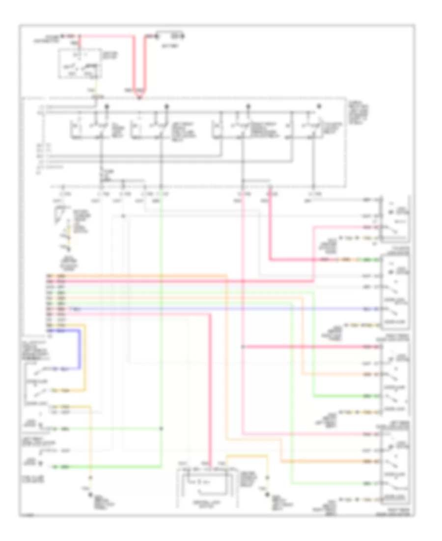
ANTI-LOCK BRAKES
Anti-lock Brake Wiring Diagrams (1 of 2) for Mercedes-Benz ML430 2000
List of elements for Anti-lock Brake Wiring Diagrams (1 of 2) for Mercedes-Benz ML430 2000:
- (behind right headlamp) g107
- A11
- Abs mil
- Asr/ets/esp hydraulic unit (in left side of engine compt, below washer bottle)
- B10
- Bas/esp mil
- Battery
- Brake assist (bas)
- Brake fluid level switch (in brake fluid reservoir)
- Brake pad wear indicator
- Can h
- Can l
- Computer data lines system
- Esp brake pressure sensor 1 (in left rear of engine compt)
- Esp brake pressure sensor 2 (in left rear of engine compt)
- Esp/sps/bas control module (in left side of engine compt, in "e" box)
- Ets mil
- Ets warning lamp
- Fuse & relay box
- Fuse & relay box (in left side of engine compt, in "e" box)
- Fuse 40a
- Fuse 7.5a
- G106 (behind left headlamp)
- Ground
- High pressure/ return pump
- High- pressure/ return pump relay
- Hot at all times
- Instrument cluster
- Left front brake pad wear sensor
- Left front hold
- Left front release
- Left front vehicle speed sensor
- Left rear brake pad wear sensor
- Left rear hold
- Left rear release
- Lf vss input
- Membrane travel sensor
- Ml/a
- Ml/b
- Ml/c
- Mr/b
- Nca
- Pnk
- Pressure 1 switchover
- Pressure 1 vacuum
- Pressure 2 switchover
- Pressure 2 vacuum
- Red
- Release switch
- Rf vss input
- Right front brake pad wear sensor
- Right front footwell fuse & relay box (below right side of dash, behind kick panel)
- Right front hold
- Right front release
- Right front vehicle speed sensor
- Right rear brake pad wear sensor
- Right rear hold
- Right rear release
- Solenoid valve
- Tan
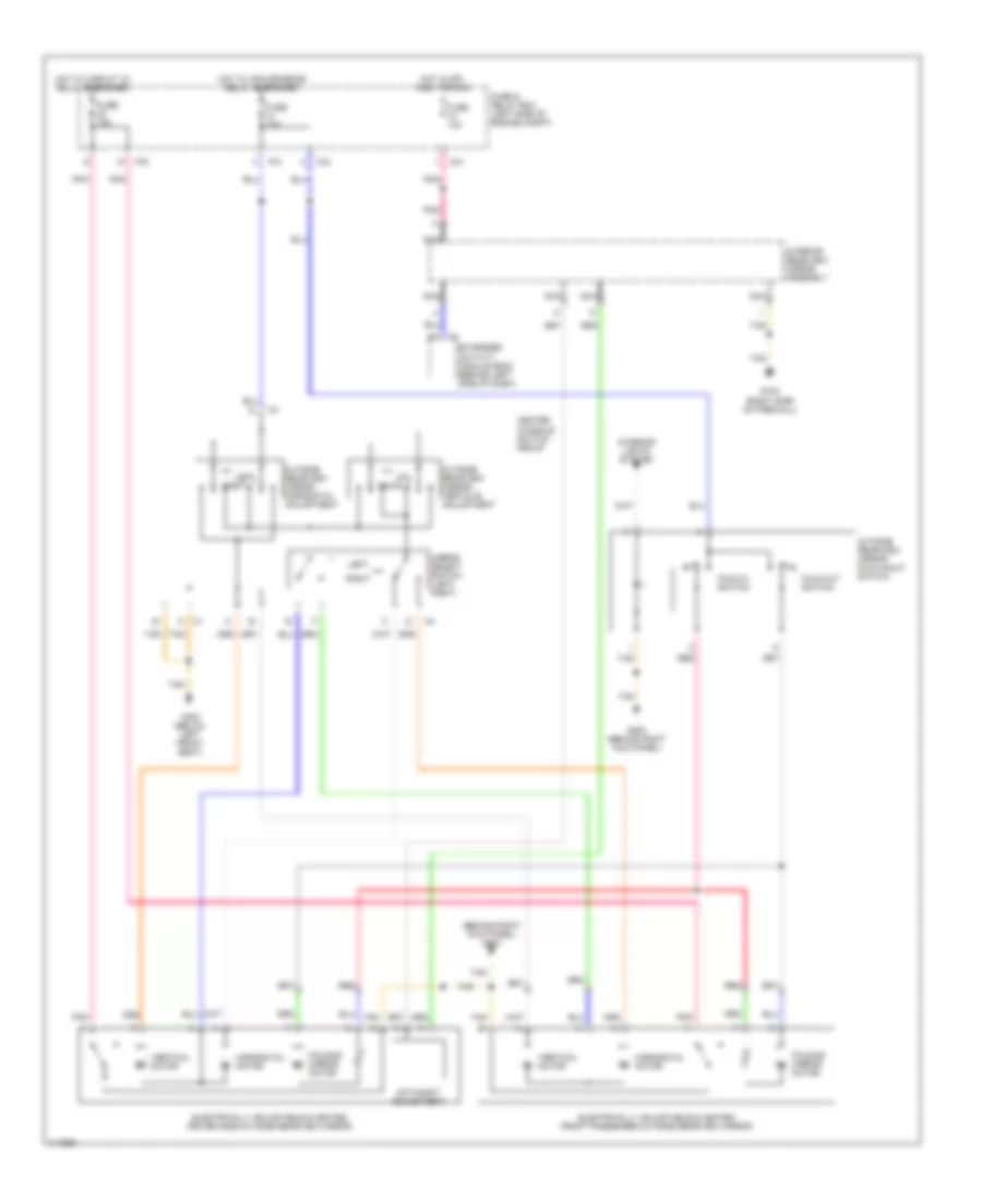
Anti-lock Brake Wiring Diagrams (2 of 2) for Mercedes-Benz ML430 2000
List of elements for Anti-lock Brake Wiring Diagrams (2 of 2) for Mercedes-Benz ML430 2000:
- 87a
- Abs lateral acceleration sensor (below center console, behind shift assembly)
- Abs speed signal connector
- All activity module (aam) (in "e" box)
- C/b
- C/c
- C/d
- C/e
- C/f
- C/h
- Circuit 15 relay
- Data link connector (dlc) (below left side of dash)
- Diagnosis
- Electronic selector lever control module (w/a/t)
- Esp off switch
- Esp/ stoplamp suppression relay
- Esp/sps/bas control module (in left side of engine compt, in "e" box)
- Fuse & relay box
- Fuse & relay box (in left side of engine compt, in "e" box)
- Fuse 10a
- Fuse 15a
- G203 (behind right kick panel)
- Gnd
- Headlamp range adjustment control module
- Hot at all times
- Hot in run or start
- Interior lights system
- Left rear vehicle speed sensor
- Lr vss input
- Nca
- P/b
- P/c
- P/d
- Parking brake switch (on parking brake support bracket)
- Pnk
- Radio
- Red
- Right rear vehicle speed sensor
- Rr vss input
- Signal
- Steering angle sensor (below driver's side of dash)
- Stoplight switch (on brake pedal support)
- Tan
- X2/4
- Yaw rate sensor (below center console, behind shift assembly)
ANTI-THEFT
Anti-theft Wiring Diagram, with Auxiliary Alarm for Mercedes-Benz ML430 2000
List of elements for Anti-theft Wiring Diagram, with Auxiliary Alarm for Mercedes-Benz ML430 2000:
- 15c
- A c1
- A10
- A12
- Acc
- Ajar
- Alarm siren (w/ auxiliary battery) (left rear of engine compt)
- All activity module (left side of engine compt, in "e" box)
- Ata ind
- B11
- B12
- Battery
- C/d
- C/e
- C3 c
- Center console switch group
- Clock
- Computer data lines system
- Cruise
- Data 1
- Data 2
- Data 3
- Data 4
- Data link connector (below left side of dash)
- Diag
- Door lock
- Double combi- nation switch
- Engine hood switch
- Extended activity module (behind left side of dash)
- Exterior lights system
- Fbm control module
- Fuse & relay box (left side of engine compt, in "e" box)
- Fuse 7.5a
- G106 (behind left headlamp)
- G107 (behind right headlamp)
- G203 (behind
- G203 (behind right kick panel)
- G300 (below
- G300 (below left front seat)
- G301 (below right front seat)
- G412 (center of tailgate)
- Glass break sensor
- Ignition key switch
- Ignition switch
- Immob
- Incline sensor
- Inhibit
- Ki 15
- Ki 15c
- Ki 30
- Ki 31
- Left front door lock motor
- Left front seat)
- Left rear door lock motor
- Lock
- Mb-immobilizer control module (right side of steering column)
- Ml/a
- Ml/c
- Mr/a
- Mr/b
- Mr/d
- Off
- On/off
- P/d
- P/e
- Pnk
- Power distribution system
- Red
- Right front door lock motor
- Right kick panel)
- Right rear door lock motor
- Run
- Start
- Tailgate lock motor
- Tan
- Trans- ponder coil
- Trip computer control module
- Trunk lid micro switch
Anti-theft Wiring Diagram, without Auxiliary Alarm for Mercedes-Benz ML430 2000
List of elements for Anti-theft Wiring Diagram, without Auxiliary Alarm for Mercedes-Benz ML430 2000:
- (behind left headlamp) g106
- (behind right headlamp) g107
- (center of tailgate) g412
- 15c
- A c1
- A10
- A12
- Acc
- Ajar
- Alarm horn (left rear corner of engine compt)
- Alarm horn relay
- All activity module (left side of engine compt, in "e" box)
- Ata ind
- B11
- B12
- Battery
- C/d
- C/e
- C3 c
- Center console switch group
- Clock
- Computer data lines system
- Cruise
- Data 1
- Data 2
- Data 3
- Data 4
- Data link connector (below left side of dash)
- Diag
- Door lock
- Double combi- nation switch
- Engine hood switch
- Extended activity module (behind left side of dash)
- Exterior lights system
- Fbm control module
- Fuse & relay box (left side of engine compt, in "e" box)
- Fuse 20a
- Fuse 7.5a
- G203 (behind
- G203 (behind right kick panel)
- G300 (below
- G300 (below left front seat)
- G301 (below right front seat)
- G412 (center of tailgate)
- Glass break sensor
- Ignition key switch
- Ignition switch
- Immob
- Incline sensor
- Inhibit
- Ki 15
- Ki 15c
- Ki 30
- Ki 31
- Left front door lock motor
- Left front seat)
- Left rear door lock motor
- Lock
- Mb-immobilizer control module (right side of steering column)
- Ml/a
- Mr/a
- Mr/d
- Off
- On/off
- P/d
- P/e
- Pnk
- Power distribution system
- Red
- Right front door lock motor
- Right kick panel)
- Right rear door lock motor
- Run
- Start
- Tailgate lock motor
- Tan
- Trans- ponder coil
- Trip computer control module
- Trunk lid micro switch
BODY COMPUTER
All Activity Module Wiring Diagram for Mercedes-Benz ML430 2000
List of elements for All Activity Module Wiring Diagram for Mercedes-Benz ML430 2000:
- 15c
- A10
- A11
- A12
- Acc
- Air conditioning system
- All activity module (left side of engine compt)
- Anti-theft system
- B10
- B11
- B12
- Battery
- C/d
- Circuit 15 relay
- Computer data lines system
- Cooling fans system
- Defogger, mirrors, power tops, power windows systems
- Door locks system
- Extended activity module (eam) (behind left side of dash)
- Exterior lights system
- Fuse & relay box (left side of engine compt, in "e" box)
- G123 (right side of firewall)
- G404 (left wheelwell in luggage compartment)
- Headlights system
- Horns system
- Ignition switch
- Instrument cluster system
- Interior lights system
- Key in
- Mr/d
- Nca
- Off
- Pnk
- Power distribution system
- Power windows system
- Rcl antenna
- Red
- Run
- Seats system
- Start
- Tan
- Trailer hitch socket
- Trailer recognition microswitch
- Trunk, tailgate, fuel doors system
- Wiper/washer system
Extended Activity Module Wiring Diagram for Mercedes-Benz ML430 2000
List of elements for Extended Activity Module Wiring Diagram for Mercedes-Benz ML430 2000:
- (behind right kick panel) g203
- 15c
- 15r
- A10
- A11
- A12
- Acc
- All activity module (aam) (left side of engine compt)
- Anti-theft system
- B10
- B11
- B12
- Battery
- C6 extended activity module (eam) (behind center of dash)
- Clock
- Computer data lines system
- Cruise control
- Cruise control system
- Data 1
- Data 2
- Data 3
- Data 4
- Defogger system
- Diagnosis
- Exterior lights system
- Fbm control module
- Hot at all times
- Immobilizer
- Inhibit
- Interior lights system
- Key in
- Ki 15
- Ki 15c
- Ki 30
- Ki 31
- Off
- On/off immobilizer
- Pnk
- Power distribution system
- Power tops system
- Red
- Run
- Seats system
- Seats, memory systems
- Start
- Starter switch
- Tan
- Wiper/washer system
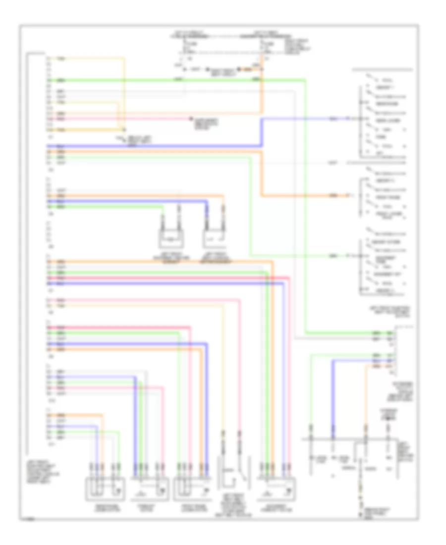
COMPUTER DATA LINES
Computer Data Lines for Mercedes-Benz ML430 2000
List of elements for Computer Data Lines for Mercedes-Benz ML430 2000:
- (not used)
- A12
- All activity module (aam)
- All activity module (aam) (in left side of engine compt, in "e" box)
- B10
- B11
- B12
- C/b
- C/c
- C/e
- C/f
- Can h
- Can l
- Data link connector (dlc) (below left side of dash)
- Diagnosis
- Egs51
- Electronic selector lever control module (under center console)
- Engine control module (me-sfi) (in left side of engine compt, in "e" box)
- Esp/sps/bas control module (in left side of engine compt, in "e" box)
- Etc control module (behind center of dash)
- Extended activity module (eam) (behind left side of dash)
- Fbm control module
- Fuse & relay box
- Fuse & relay box (in left side of engine compt, in "e" box)
- Fuse 10a
- Fuse 15a
- G123 (right side of firewall)
- G203 (behind right kick panel)
- Hot at all times
- Hot in run or start
- Instrument cluster
- Mr/d
- Mr/e
- Msg prog
- P/b
- Pnk
- Radio
- Red
- Restraint system control module (below front of center console)
- Tan
- Transfer case control module (below center console, behind shift assembly)
- Trip computer control module (in front of roof)
- X18
COOLING FAN
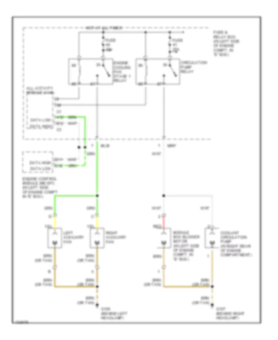
Cooling Fan Wiring Diagram for Mercedes-Benz ML430 2000
List of elements for Cooling Fan Wiring Diagram for Mercedes-Benz ML430 2000:
- A12
- All activity module (aam)
- B12
- Circulation pump relay
- Coolant circulation pump (in right rear of engine compartment)
- D11
- D12
- Data high
- Data low
- Engine control module (me-sfi) (in left side of engine compt in "e" box)
- Engine cooling fan stage 1 relay
- Fuse & relay box (in left side of engine compt, in "e" box)
- Fuse 25a
- Fuse 30a
- G106 (behind left headlamp)
- G107 (behind right headlamp)
- Hot at all times
- Left auxiliary fan
- Ml/b
- Module box blower motor (in left side of engine compt, in "e" box)
- Mr/f
- Red
- Right auxiliary fan
CRUISE CONTROL
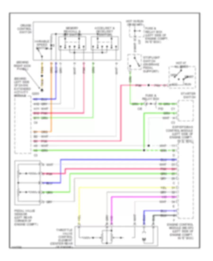
Cruise Control Wiring Diagram for Mercedes-Benz ML430 2000
List of elements for Cruise Control Wiring Diagram for Mercedes-Benz ML430 2000:
- (behind left side of dash) extended activity module
- (behind right kick panel)
- A11
- A12
- Acc
- Accel/set & decel/set switch
- B11
- B12
- C/e
- C/f
- Cruise control switch
- Engine control module (me-sfi) (left side of engine compt, in "e" box)
- Esp/sps/bas control module (left side of engine compt, in "e" box)
- Fuse & relay box
- Fuse & relay box (left side of engine compt, in "e" box)
- G203
- Hot at all times
- Hot in run or start
- Memory reacall & off switch
- Off
- P/d
- Pedal value sensor (left rear corner of engine compt)
- Pnk
- Run
- Start
- Starter switch
- Stoplight switch (on brake pedal support)
- Tan
- Throttle valve control element (center rear of engine)
- Variable speed switch
DEFOGGERS
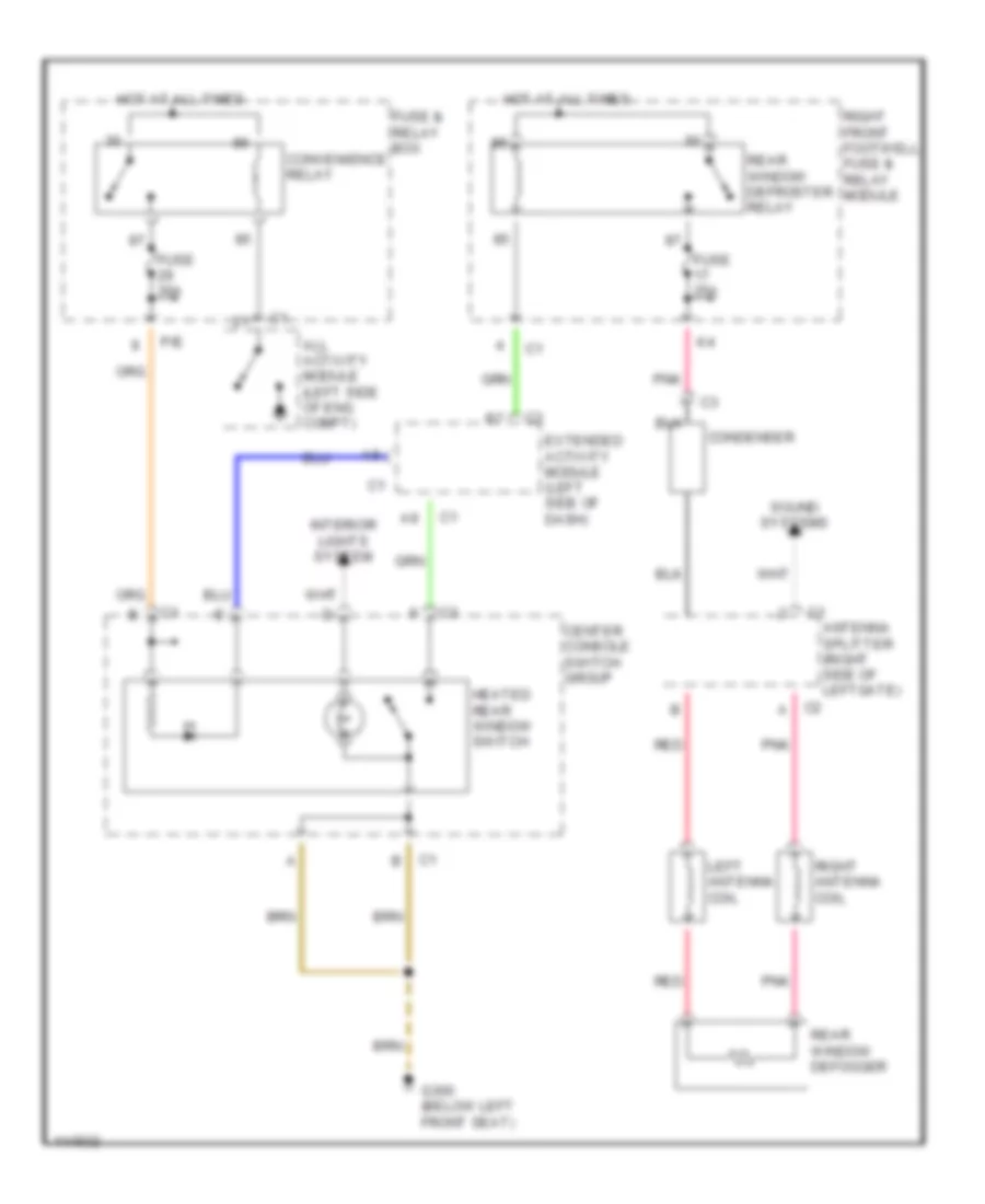
Defogger Wiring Diagram for Mercedes-Benz ML430 2000
List of elements for Defogger Wiring Diagram for Mercedes-Benz ML430 2000:
- All activity module (left side of eng compt)
- Antenna splitter (right side of leftgate)
- C2 a
- Center console switch group
- Condenser
- Convenience relay
- Extended activity module (left side of dash)
- Fuse & relay box
- Fuse 25a
- Fuse 30a
- G300 (below left front seat)
- Heated rear window switch
- Hot at all times
- Interior lights system
- Left antenna coil
- P/e
- Pnk
- Rear window defogger
- Rear window defroster relay
- Red
- Right antenna coil
- Right front footwell fuse & relay module
- Sound systems
ENGINE PERFORMANCE
4.3L, Engine Performance Wiring Diagrams (1 of 3) for Mercedes-Benz ML430 2000
List of elements for 4.3L, Engine Performance Wiring Diagrams (1 of 3) for Mercedes-Benz ML430 2000:
- A11
- B10
- C/f
- Can(h)+
- Can(l)-
- Data link connector (dtc readout) (below left side of dash)
- Engine control module (me-sfi) (left side of engine compt, in e box)
- Etc control module (behind center of dash)
- Fuse & relay box (left side of engine compt)
- Fuse 7.5a
- G104 (left rear corner of engine compt)
- Hot at all times
- Instrument cluster
- Left oxygen sensor 1 (before twc) (in exhaust pipe)
- Left oxygen sensor 2 (after twc) (in exhaust pipe)
- Low engine oil indicator
- Malfunction indicator
- Mr/e
- Nca
- Pedal value sensor (left rear corner of engine compt)
- Pnk
- Purge control valve (left rear corner of engine compt)
- Red
- Right front footwell fuse & relay box
- Right oxygen sensor 1 (before twc) (in exhaust pipe)
- Right oxygen sensor 2 (after twc) (in exhaust pipe)
- Starting system
4.3L, Engine Performance Wiring Diagrams (2 of 3) for Mercedes-Benz ML430 2000
List of elements for 4.3L, Engine Performance Wiring Diagrams (2 of 3) for Mercedes-Benz ML430 2000:
- (right front of engine) air pump switchover valve
- (top center front of engine) shifting induction pipe switchover valve
- (top rear of engine) egr switchover valve
- Activated charcoal canister shut-off valve (under rear of vehicle, above spare wheel)
- Air pump (center front of engine)
- Battery
- Camshaft hall-effect sensor (right front of engine)
- Ckp sensor (left rear of engine)
- Fuel pump
- Fuel pump relay
- Fuel pump with fuel level sensor (top of fuel tank)
- Fuel tank emissions monitoring pressure sensor (behind trim on fuel filler pipe)
- Fuse & relay box (left side of engine compt)
- Fuse 15a
- Fuse 20a
- Fuse 40a
- G125 (front of engine)
- G404 (left rear cargo area)
- Hot film maf sensor (right side of engine compartment)
- Hot in run or start
- M/a
- M/c
- Mr/a
- Mr/c
- Mr/d
- Mr/e
- P/a
- P/d
- P/e
- Pnk
- Red
- Secondary air injection pump relay
- Throttle valve actuator (center rear of engine)
4.3L, Engine Performance Wiring Diagrams (3 of 3) for Mercedes-Benz ML430 2000
List of elements for 4.3L, Engine Performance Wiring Diagrams (3 of 3) for Mercedes-Benz ML430 2000:
- (center front of engine) ect sensor
- (lower right front of engine) oil sensor
- (right front of engine) pressure sensor
- Engine control module (me-sfi) (left side of engine compt, in e box)
- Fuel injectors
- Fuse & relay box (left side of engine compt)
- Fuse 10a
- Fuse 15a
- G104 (left rear corner of engine compt)
- Hot in run or start
- Ign coil
- Ign coil coil
- Knock sensor 1 (right side of engine)
- Knock sensor 2 (left side of engine)
- M/a
- M/c
- Nca
- Pnk
- Red
- To spark plugs
EXTERIOR LIGHTS
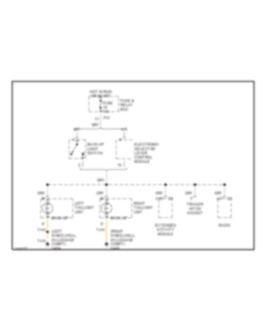
Back-up Lamps Wiring Diagram for Mercedes-Benz ML430 2000
List of elements for Back-up Lamps Wiring Diagram for Mercedes-Benz ML430 2000:
- (left wheelwell, in luggage compt) g404
- (right wheelwell, in luggage compt) g405
- A/t
- A10
- Back-up
- Back-up light switch
- Electronic selector lever control module
- Extended activity module
- Fuse & relay box
- Fuse 15a
- Hot in run or start
- Left taillight unit
- M/t
- P/c
- Radio
- Right taillight unit
- Tan
- Trailer hitch socket
Exterior Light Wiring Diagram (1 of 2) for Mercedes-Benz ML430 2000
List of elements for Exterior Light Wiring Diagram (1 of 2) for Mercedes-Benz ML430 2000:
- (behind right kick panel) g203
- 56a
- 56d
- 58l
- 58r
- 87a
- A11
- Accy
- All activity module
- All activity module (left side of engine compt)
- C/b
- C/d
- C/e
- Circuit relay
- Combination switch
- Flash
- From fuse 46 (diagram 2 of 2)
- Front & rear fog lamps switch
- Fuse & relay box (left side of engine compt)
- Fuse 7.5a
- G203 (behind right kick panel)
- G412 (center of tailgate)
- Hazard flasher switch
- Head
- Headlamp flasher/ high beam switch
- Headlamp range adjustment control module
- Headlights system
- High
- Hot at all times
- Illum
- Instrument cluster system
- Interior lights system
- Left license plate lamp
- Light switch
- Low
- Ml/a
- Mr/d
- Off
- P/b
- P/e
- P30
- Park
- Pnk
- Rear fog lamps on ind
- Right license plate lamp
- Run
- Shorting clip
- Standing
- Start
- Starter switch
- Tan
- To left headlamp unit (diagram 2 of 2)
- To left taillamp unit (diagram 2 of 2)
- To right headlamp unit (diagram 2 of 2)
- To right taillamp unit (diagram 2 of 2)
- Turn signal switch
Exterior Light Wiring Diagram (2 of 2) for Mercedes-Benz ML430 2000
List of elements for Exterior Light Wiring Diagram (2 of 2) for Mercedes-Benz ML430 2000:
- (left wheelwell, in luggage compt) g404
- (not used)
- (right wheelwell, in luggage compt) g405
- 87a
- A10
- All activity module
- Anti-lock brakes system
- C/c
- C/e
- C/f
- C/h
- Center high mounted stop lamp
- Circuit relay
- Electronic selctor lever control module
- Esp stoplight suppres- sion relay
- Fog
- From fuse 12 (diagram 1 of 2)
- From fuse 24 (diagram 1 of 2)
- Fuse & relay box (left side of engine compt)
- Fuse 10a
- Fuse 25a
- Fuse 7.5a
- G106 (behind left headlamp)
- G107 (behind right headlamp)
- G203 (behind right kick panel)
- G404 (left wheelwell, in luggage compt)
- G412 (center of tailgate)
- Hot at all times
- Instrument cluster
- Left auxiliary turn signal lamp
- Left headlamp unit
- Left taillamp unit
- Left turn ind
- Left turn signal relay
- Ml/a
- Mr/d
- P/a
- P/c
- P/d
- P/e
- Pnk
- Rear fog lamp relay
- Red
- Right auxiliary turn signal lamp
- Right headlamp unit
- Right taillamp unit
- Right turn ind
- Right turn signal relay
- Sounder
- Standing/ parking
- Stop
- Stop lamp switch
- Tail/ parking
- Tan
- To combination switch (diagram 1 of 2)
- Trailer hitch socket
- Trailer turn signal control module (integral to trailer harness)
- Turn signal
- W/ door mounted spare wheel
- W/o door mounted spare wheel
GROUND DISTRIBUTION
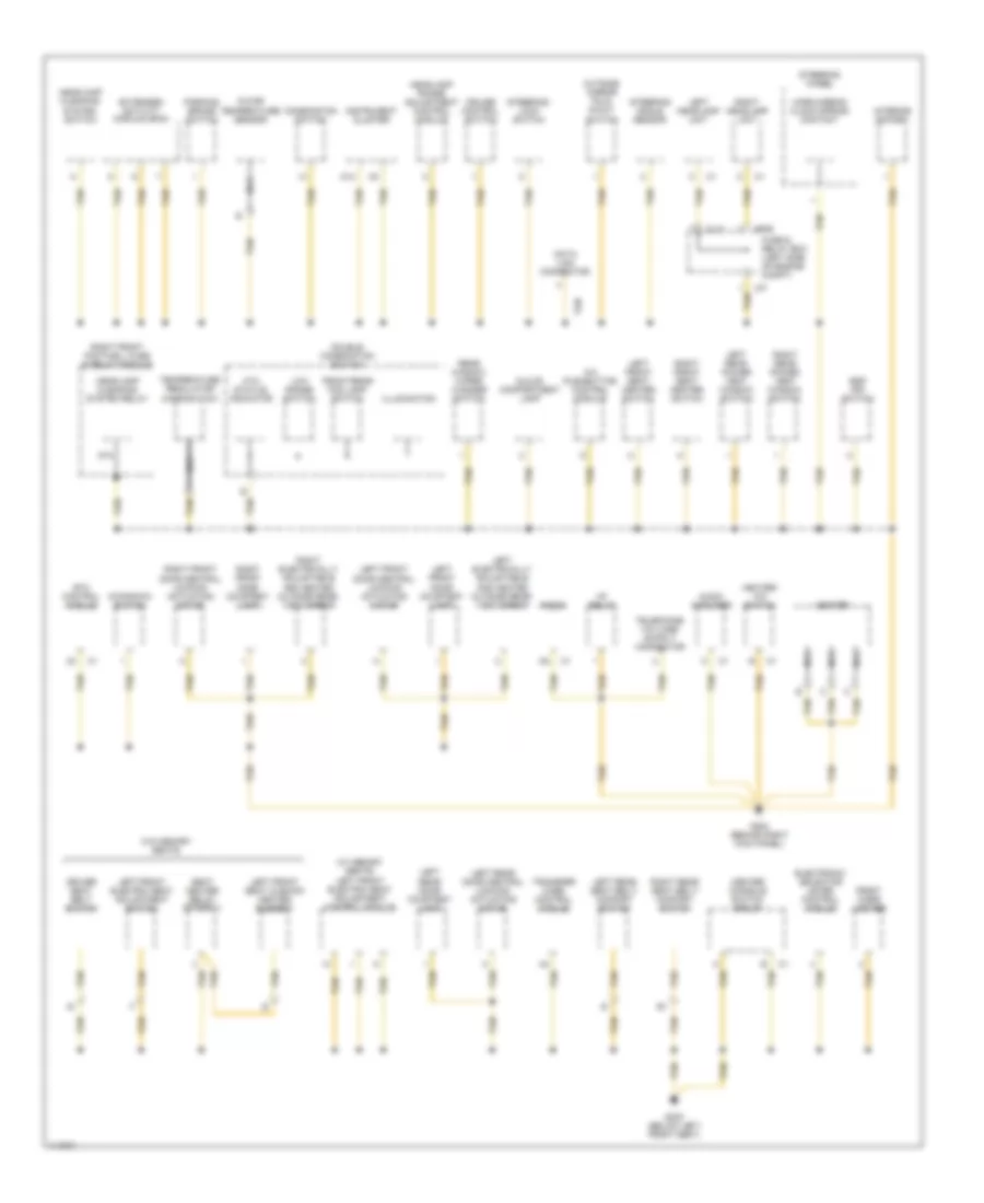
Ground Distribution Wiring Diagram (1 of 3) for Mercedes-Benz ML430 2000
List of elements for Ground Distribution Wiring Diagram (1 of 3) for Mercedes-Benz ML430 2000:
- Alarm horn
- Alarm siren w/ auxiliary battery
- All activity module
- Asr/ets/esp hydraulic unit
- Battery
- Brake fluid level switch
- C/b
- C/h
- Coolant circulation pump
- Data link connector
- Engine control module
- Engine hood switch
- Esp/sps/bas control module
- Front dome light
- Fuse & relay box (left side of engine compt)
- G106 (behind left headlamp)
- G107 (behind right headlamp)
- G116 (left side of firewall)
- G123 (right side of firewall)
- Garage door opener transmitter
- Headlamp washer pump
- Interior rearview mirror assembly
- Left auxiliary fan
- Left auxiliary turn signal lamp
- Left fog lamp
- Left headlamp unit
- Left rear dome light
- Left sun visor
- Module box blower motor
- Mr/d
- Nca
- Rain sensor
- Rear dome light
- Rear window washer pump
- Right auxiliary fan
- Right auxiliary turn signal lamp
- Right fog lamp
- Right headlamp unit
- Right rear dome light
- Right sun visor
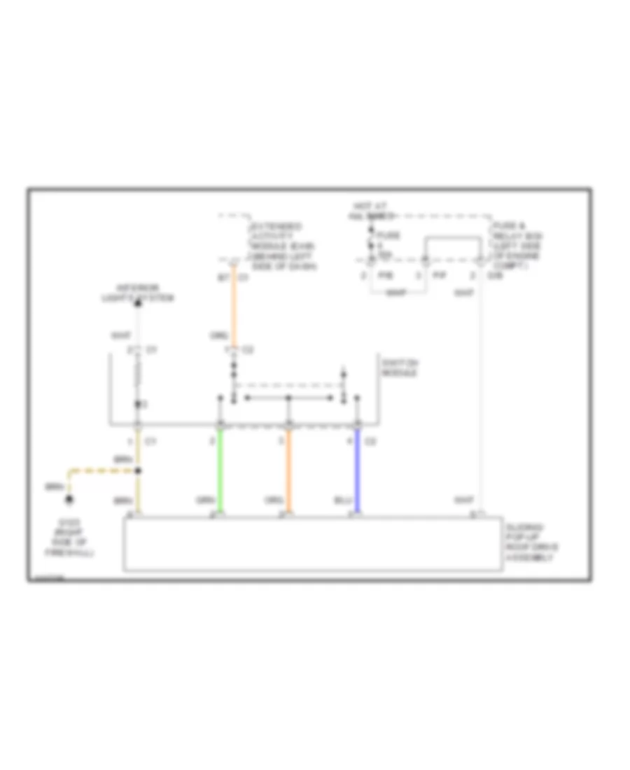
- Sliding/ pop-up roof drive assembly
- Sun- roof switch
- Tan
- Trip computer control module
- Two-tone horn
- Windshield washer pump
- Wiper motor
- X11/14
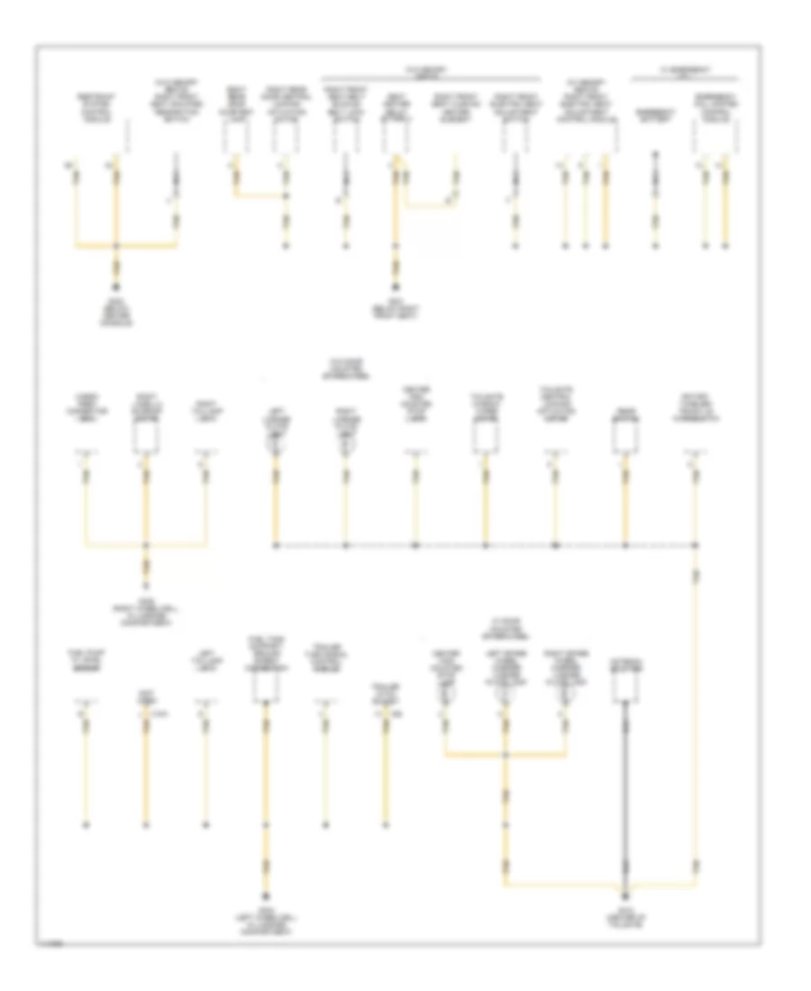
Ground Distribution Wiring Diagram (2 of 3) for Mercedes-Benz ML430 2000
List of elements for Ground Distribution Wiring Diagram (2 of 3) for Mercedes-Benz ML430 2000:
- (w/ memory seats) left front electric seat adjustment control module
- 87a
- A/c pushbutton control module
- A12
- Ata status indicator
- Audio amplifier
- C/f
- Center console switch group
- Combination switch
- Cruise control switch
- Data link connector
- Double combination switch
- Driver seat belt switch
- Electronic selector lever control module
- Esp off switch
- Etc control module
- Extended activity module (eam)
- Front cigar lighter
- Front/rear fog lamp switch
- Fuse & relay box (left side of engine compt)
- G203 (behind right kick panel)
- G300 (below left front seat)
- Glove compartment lamp
- Headlamp cleaning system relay
- Headlamp cleaning system switch
- Headlamp range adjustment control module
- Heater
- Heater/ a/c switch
- Hf relay
- Horn/airbag clock spring contact
- Illumination
- In-car temperature sensor
- Instrument cluster
- Interior socket
- Kickdown switch
- Left electrically adjustable and heated outside rear- view mirror
- Left front door central locking actuating motor
- Left front door courtesy lamp
- Left front electric seat adjustment switch
- Left front seat cushion heater element
- Left front seat heater switch
- Left headlamp unit
- Left rear door central locking actuating motor
- Left rear door courtesy lamp
- Left rear power vent window switch
- Left rear seat belt/ comfort switch
- Low range switch
- Ml/c
- Mr/e
- Nca
- Outside mirror fold in/out switch
- Parking brake switch
- Radio
- Rear window wiper/ washer switch
- Right electrically adjustable and heated outside rear- view mirror
- Right front door central locking actuating motor
- Right front door courtesy lamp
- Right front footwell fuse & relay module
- Right front seat heater switch
- Right headlamp unit
- Right rear power vent window switch
- Right rear seat belt/ comfort switch
- Seat heater relay (stage 1)
- Steering angle sensor
- Steering wheel
- Steering- lock switch
- Tan
- Temperature regulator microswitch
- Transfer case control module
- W/o memory seats
Ground Distribution Wiring Diagram (3 of 3) for Mercedes-Benz ML430 2000
List of elements for Ground Distribution Wiring Diagram (3 of 3) for Mercedes-Benz ML430 2000:
- (not used)
- (w/ memory seats) right front electric seat adjustment control module
- (w/o memory seats) right front seat occupied recognition switch
- Antenna splitter
- Cargo area connector box
- Center high mounted stop lamp
- Emergency battery
- Emergency call system control module
- Fuel pump w/ level sensor
- Fuel tank support/ ground screw connection
- G301 (below right front seat)
- G302 (below center console)
- G404 (left wheelwell in luggage compartment)
- G405 (right wheelwell, in luggage compartment)
- G412 (center of tailgate)
- Left license plate light
- Left spare wheel carrier license plate lamp
- Left taillamp unit
- Nca
- Rear switch
- Restraint system control module
- Right front electric seat adjustment switch
- Right front seat belt buckle/ belt lock switch
- Right front seat cushion heater element
- Right lamella sunroof motor
- Right license plate light
- Right rear door central locking actuating motor
- Right rear door courtesy lamp
- Right spare wheel carrier license plate lamp
- Right taillamp unit
- Rotary tumbler/ trunk lid microswitch
- Seat heater relay (stage 1)
- Tailgate central locking actuating motor
- Tailgate window wiper motor
- Tan
- Trailer hitch socket
- Trailer turn signal control module
- W/ door mounted spare wheel
- W/ emergency call
- W/o door mounted spare wheel
- W/o memory seats
- X18/3
- X58
HEADLIGHTS
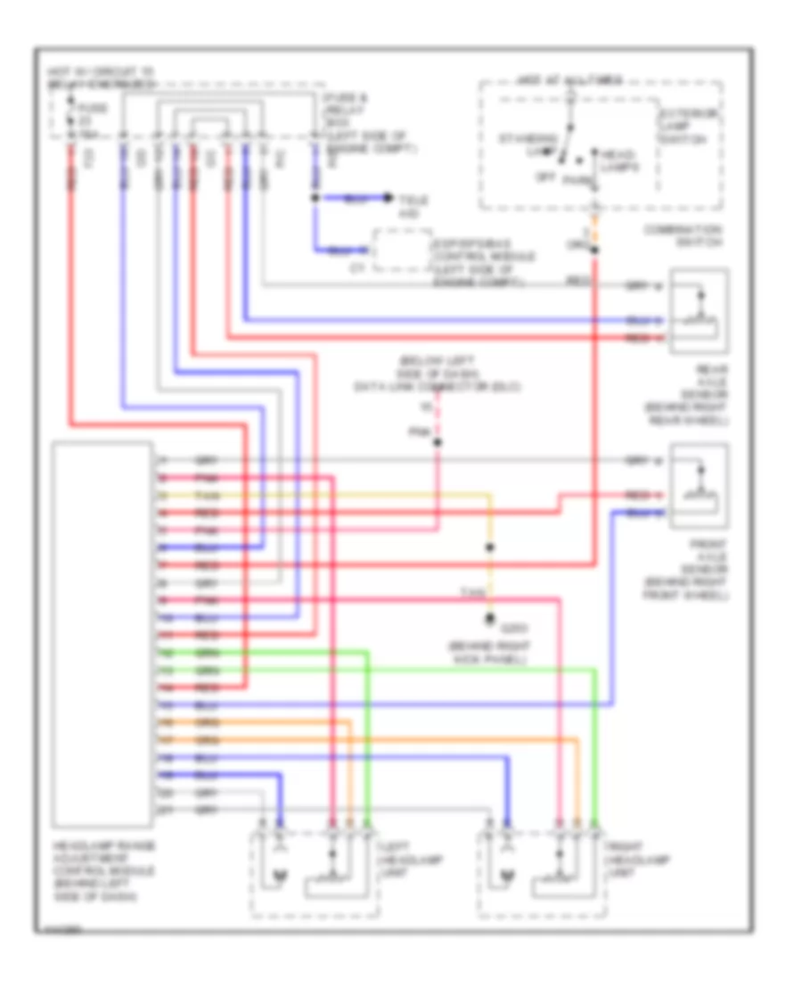
Headlamps Leveling Wiring Diagram for Mercedes-Benz ML430 2000
List of elements for Headlamps Leveling Wiring Diagram for Mercedes-Benz ML430 2000:
- (behind right kick panel)
- (below left side of dash) data link connector (dlc)
- C/c red
- Combination switch
- Esp/sps/bas control module (left side of engine compt)
- Exterior lamp switch
- F23 red
- Front axle sensor (behind right front wheel)
- Fuse & relay box (left side of engine compt)
- Fuse 15a
- G203
- Head- lamps
- Headlamp range adjustment control module (behind left side of dash)
- Hot at all times
- Hot w/ circuit 15 relay energized
- Left headlamp unit
- Off park
- Pnk
- Rear axle sensor (behind right rear wheel)
- Red
- Right headlamp unit
- Standing lamp
- Tan
- Tele aid
Headlight Wiring Diagram, with Xenon Lamps (1 of 2) for Mercedes-Benz ML430 2000
List of elements for Headlight Wiring Diagram, with Xenon Lamps (1 of 2) for Mercedes-Benz ML430 2000:
- (left side of engine compartment) all activity module
- 56a
- 56d
- 58l
- 58r
- 87a
- A11
- Accy
- C/b
- C/d
- C/e
- Circuit relay
- Combination switch
- Exterior lights system
- Flash
- Fuse & relay box (left side of engine compt)
- Fuse 7.5a
- Head
- Headlamp flasher switch
- High
- Hot at all times
- Instrument cluster system
- Light switch
- Low
- Ml/a
- Mr/d
- Off
- P/b
- P/e
- P30
- Park
- Pnk
- Run
- Shorting clip
- Standing
- Start
- Starter switch
- Tan
- To instrument cluster (diagram 2 of 2)
- To left headlamp unit (diagram 2 of 2)
- To right headlamp unit (diagram 2 of 2)
- Turn signal switch
Headlight Wiring Diagram, with Xenon Lamps (2 of 2) for Mercedes-Benz ML430 2000
List of elements for Headlight Wiring Diagram, with Xenon Lamps (2 of 2) for Mercedes-Benz ML430 2000:
- A12
- All activity module (left side of engine compt)
- B10
- B12
- C/e
- Computer data lines system
- Double combination switch
- Fog lamp indicator
- From fuse 3 (diagram 1 of 2)
- From fuse 34 (diagram 1 of 2)
- From fuse 35 (diagram 1 of 2)
- From fuse 5 (diagram 1 of 2)
- Front foglight relay
- Front/rear fog lamp switch
- Fuse & relay box (left side of engine compt)
- Fuse 15a
- Fuse 7.5a
- G106 (behind left headlamp)
- G107 (behind right headlamp)
- G203 (behind right kick panel)
- G404 (left wheelwell in luggage compartment)
- High beam
- High beam indicator
- Hot at all times
- Instrument cluster
- Left front fog lamp
- Left headlamp unit
- Left taillamp unit
- Low beam
- Ml/c
- P/e
- Pnk
- Rear fog lamp
- Rear fog lamp indicator lamp
- Rear foglight relay
- Red
- Right front fog lamp
- Right headlamp unit
- Tan
- Xenon headlamp control module
- Xenon headlamp ignition module
Headlight Wiring Diagram, without Xenon Lamps (1 of 2) for Mercedes-Benz ML430 2000
List of elements for Headlight Wiring Diagram, without Xenon Lamps (1 of 2) for Mercedes-Benz ML430 2000:
- (left side of engine compartment) all activity module
- 56a
- 56d
- 58l
- 58r
- 87a
- A11
- Accy
- C/b
- C/d
- C/e
- Circuit relay
- Combination switch
- Exterior lights system
- Flash
- Fuse & relay box (left side of engine compt)
- Fuse 7.5a
- Head
- Headlamp flasher switch
- High
- Hot at all times
- Instrument cluster system
- Light switch
- Low
- Ml/a
- Mr/d
- Off
- P/b
- P/e
- P30
- Park
- Pnk
- Run
- Shorting clip
- Standing
- Start
- Starter switch
- Tan
- To instrument cluster (diagram 2 of 2)
- To left headlamp unit (diagram 2 of 2)
- To right headlamp unit (diagram 2 of 2)
- Turn signal switch
Headlight Wiring Diagram, without Xenon Lamps (2 of 2) for Mercedes-Benz ML430 2000
List of elements for Headlight Wiring Diagram, without Xenon Lamps (2 of 2) for Mercedes-Benz ML430 2000:
- A12
- All activity module (left side of engine compt)
- B10
- B12
- C/e
- Computer data lines system
- Double combination switch
- Fog lamp indicator
- From fuse 3 (diagram 1 of 2)
- From fuse 34 (diagram 1 of 2)
- From fuse 35 (diagram 1 of 2)
- From fuse 5 (diagram 1 of 2)
- Front foglight relay
- Front/rear fog lamp switch
- Fuse & relay box (left side of engine compt)
- Fuse 15a
- Fuse 7.5a
- G106 (behind left headlamp)
- G107 (behind right headlamp)
- G203 (behind right kick panel)
- G404 (left wheelwell in luggage compartment)
- High beam
- High beam indicator
- Hot at all times
- Instrument cluster
- Left front fog lamp
- Left headlamp unit
- Left taillamp unit
- Low beam
- Ml/c
- P/e
- Pnk
- Rear fog lamp
- Rear fog lamp indicator lamp
- Rear foglight relay
- Red
- Right front fog lamp
- Right headlamp unit
- Tan
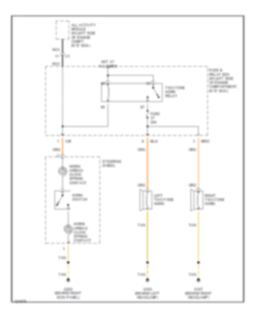
HORN
Horn Wiring Diagram for Mercedes-Benz ML430 2000
List of elements for Horn Wiring Diagram for Mercedes-Benz ML430 2000:
- All activity module (in left side of engine compt, in "e" box)
- C/b
- Fuse 20a
- Fuse & relay box (in left side of engine compartment, in "e" box)
- G106 (behind left headlamp)
- G107 (behind right headlamp)
- G203 (behind right kick panel)
- Horn switch
- Horn/ airbag clock spring contact
- Hot at all times
- Left two-tone horn
- Ml/a
- Mr/c
- Nca
- Right two-tone horn
- Steering wheel
- Tan
- Two-tone horn relay
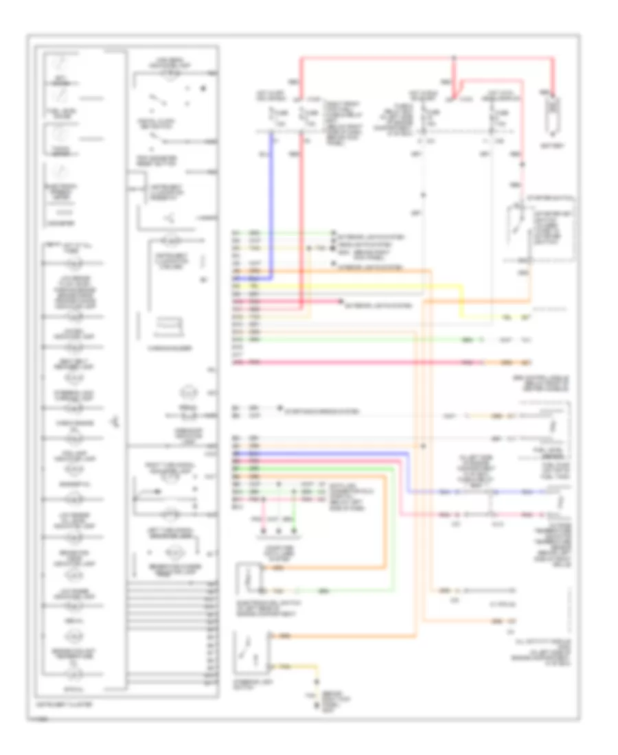
INSTRUMENT CLUSTER
Instrument Cluster Wiring Diagram for Mercedes-Benz ML430 2000
List of elements for Instrument Cluster Wiring Diagram for Mercedes-Benz ML430 2000:
- (behind right kick panel)
- (behind right kick panel) g203
- (in left side of engine compartment in "e" box) fuse & relay box
- 0 0 0 0
- 15c
- A10
- A11
- A12
- A13
- A14
- A15
- A16
- A17
- A18
- Abs mil
- Airbag off indicator lamp
- All activity module (aam) (in left side of engine compartment, in "e" box)
- B10
- B11
- B12
- Bas/esp mil
- Battery
- Brake pad wear indicator lamp
- C/b
- C/c
- C/d
- C1 (pin 23)
- Check engine mil
- Computer data lines system
- Data link connector (dlc) (partial) (below left side of dash)
- Digital clock set switch
- Ect gauge
- Electronic ecl switch (in left rear of engine compartment)
- Electronic speedo- meter
- Engine coolant temperature mil
- Ets mil
- Exterior lights system
- Fog lamp indicator lamp
- Fuel level gauge
- Fuel level sensor
- Fuel pump (on top of fuel tank)
- Fuse & relay box (in left side of engine compartment, in "e" box)
- Fuse 15a
- Fuse 7.5a
- G203
- Generator charge indicator lamp
- Headlights system
- High beam indicator lamp
- Hot at all times
- Hot in off, acc or run
- Hot in run or start
- Hot with headlamps on
- Instrument cluster
- Instrument illumination (3 bulbs)
- Instrument illumination rheostat
- Interior lights system
- Left turn signal indicator lamp
- Low brake fluid level/ parking brake/ brake-force proportioning indicator lamp
- Low ecl indicator lamp
- Low engine oil level indicator lamp
- Low range indicator lamp
- Ml/a
- Odometer
- Outside temperature indicator temperature sensor (behind left side of front grille)
- Pnk
- Red
- Right front footwell fuse & relay box (below right side of dash, behind kick panel)
- Right turn signal indicator lamp
- Seat belt reminder lamp
- Srs control module (below front of center console)
- Srs mil
- Starter key switch (closed w/key in starter switch)
- Starter switch
- Starting/charging system
- Steering lock switch
- Steering lock warning lamp
- Tacho- meter
- Tan
- Trip odometer reset button
- Warning buzzer
- X12/3
- X12/9
INTERIOR LIGHTS
Courtesy Lamps Wiring Diagram (1 of 2) for Mercedes-Benz ML430 2000
List of elements for Courtesy Lamps Wiring Diagram (1 of 2) for Mercedes-Benz ML430 2000:
- All activity module (aam) (in left side of engine compt, in "e" box)
- B11
- D/a
- Front dome lamp (with shut-off delay & front reading lamp)
- Fuse & relay box
- Fuse & relay box (in left side of engine compt, in "e" box)
- Fuse 10a
- G123 (right side of firewall)
- G203 (behind right kick panel)
- G300 (below left front seat)
- G301 (below right front seat)
- Hot at all times
- Left front door central locking actuating motor
- Left front footwell illumination lamp
- Left rear dome lamp
- Left rear door central locking actuating motor
- P/d
- Rear dome lamp
- Red
- Right front door central locking actuating motor
- Right front footwell illumination lamp
- Right rear dome lamp
- Right rear door central locking actuating motor
- Rotary tumbler micro- switch
- Rotary tumbler/ trunk lid micro- switch
- Tan
Courtesy Lamps Wiring Diagram (2 of 2) for Mercedes-Benz ML430 2000
List of elements for Courtesy Lamps Wiring Diagram (2 of 2) for Mercedes-Benz ML430 2000:
- B10
- B11
- B12
- C/b
- D/a
- Extended activity module (eam) (behind left side of dash)
- Fuse & relay box (in left side of engine compt, in "e" box)
- Fuse 10a
- G123 (right side of firewall)
- G203 (behind right kick panel)
- G300 (below left front seat)
- G301 (below right front seat)
- Glove compartment lamp
- Hot in acc, run or start
- Left front door entrance/ exit lamp
- Left rear door entrance/ exit lamp
- Left sun visor (with illuminated vanity mirror)
- Nca
- Pnk
- Right front door entrance/ exit lamp
- Right rear door entrance/ exit lamp
- Right sun visor (with illuminated vanity mirror)
- Tan
Instrument Illumination Wiring Diagram for Mercedes-Benz ML430 2000
List of elements for Instrument Illumination Wiring Diagram for Mercedes-Benz ML430 2000:
- A11
- A13
- C/b
- C/e
- C1 a6
- C2 a
- C3 d
- Cargo area connector box
- Center console switch group
- Combination switch
- D/b
- Double combi- nation switch
- Electronic selector lever control module
- Esp off switch
- Exterior lamp switch
- Front cigar lighter
- Front dome lamp
- Fuse & relay box (in left side of engine compt, in "e" box)
- Fuse 20a
- Fuse 7.5a
- G123 (right side of firewall)
- G203 (behind right kick panel)
- G300 (below left front seat)
- G405 (right wheelwell, in luggage compartment)
- Hcs switch (or headlamp range adjustment control module)
- Head
- Heater/ a/c switch
- Hot at all times
- Illumi- nation
- Illumination
- Instrument cluster
- Instrument illumination rheostat
- Lamella sunroof switch
- Left front seat heater switch
- Left rear power vent window switch
- Off
- Outside rearview mirror fold in/out switch
- P/c
- P/e
- Park
- Radio
- Rear window wiper/ washer switch
- Red
- Right front footwell fuse & relay box (below right side of dash, behind kick panel)
- Right front seat heater switch
- Right rear power vent window switch
- Solid state
- Sr switch
- Standing
- Switch illumination
- Tan
- W/ lamella sunroof
- W/ sunroof
- W/o sunroof
MEMORY SYSTEMS
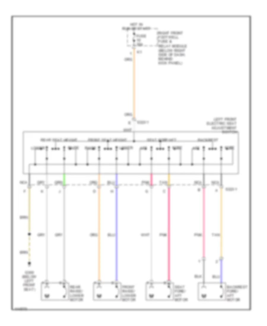
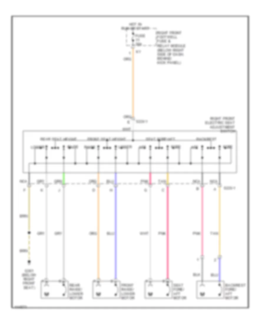
Driver's Memory Seat Wiring Diagram for Mercedes-Benz ML430 2000
List of elements for Driver's Memory Seat Wiring Diagram for Mercedes-Benz ML430 2000:
- (behind right kick panel) g203
- (below left front seat) g300
- A10
- Aft
- Backrest aft
- Backrest fore
- Backrest fore/aft motor
- C10
- C11
- Extended activity module (behind left side of dash)
- Fore
- Fore/aft motor
- Front lower
- Front raise
- Front raise/ lower motor
- Fuse 20a
- Fuse 30a
- Hot w/ circuit 15 relay energized
- Hot w/ seat comfort relay energized
- Interior lights system
- Left front backrest heater element
- Left front electric seat adjustment control module (under left front seat)
- Left front electric seat adjustment switch
- Left front seat belt buckle/belt lock switch (in driver's seat belt buckle)
- Left front seat cushion heater element
- Left front seat heater switch
- Level 1 ind
- Level 2 ind
- Memory 1
- Memory 2
- Memory 3
- Memory store
- Nca
- Normal
- Pnk
- Rapid
- Rear lower
- Rear raise
- Rear raise/ lower motor
- Right front footwell fuse & relay module
- Right front seat circuit
- Tan
Passenger's Memory Seat Wiring Diagram for Mercedes-Benz ML430 2000
List of elements for Passenger's Memory Seat Wiring Diagram for Mercedes-Benz ML430 2000:
- (behind right kick panel) g203
- (below right front seat) g301
- Aft
- Backrest aft
- Backrest fore
- Backrest fore/aft motor
- C10
- C11
- Extended activity module (behind left side of dash)
- Fore
- Fore/aft motor
- Front lower
- Front passenger seat occupied recognition w/ automatic child seat recognition
- Front raise
- Front raise/ lower motor
- Fuse 20a
- Fuse 30a
- Hot w/ circuit 15 relay energized
- Hot w/ seat comfort relay energized
- Interior lights system
- Level 1 ind
- Level 2 ind
- Memory 1
- Memory 2
- Memory 3
- Memory store
- Nca
- Normal
- Pnk
- Rapid
- Rear lower
- Rear raise
- Rear raise/ lower motor
- Red
- Right front backrest heater element
- Right front electric seat adjustment control module (under right front seat)
- Right front electric seat adjustment switch
- Right front footwell fuse & relay module
- Right front seat belt buckle/belt lock switch (in driver's seat belt buckle)
- Right front seat circuit
- Right front seat cushion heater element
- Right front seat heater switch
- Tan
POWER DISTRIBUTION
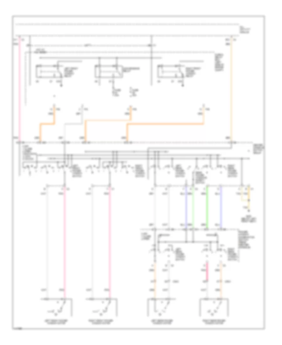
Power Distribution Wiring Diagram (1 of 4) for Mercedes-Benz ML430 2000
List of elements for Power Distribution Wiring Diagram (1 of 4) for Mercedes-Benz ML430 2000:
- (not used)
- (right wheelwell, in luggage compt) g405
- 15c
- 15r
- A/c system
- A10
- Abs system
- Accy
- Alarm siren
- All activity module
- Battery
- C/b
- C/c
- C/d
- C/e
- C/f
- Cargo area connector
- Circuit relay
- Combination switch
- D/a
- Data link connector (dlc) (dtc readout)
- Engine control module (me-sfi)
- Engine controls system
- Engine controls system, anti-lock brakes system, transmissions system
- Engine controls systems
- Extended activity module (eam)
- Exterior lights system
- F23
- From e fuse 18 (diagram 1 of 4)
- From f fuse 19 (diagram 1 of 4)
- From fuse 13 (diagram 1 of 4)
- Fuel pump relay
- Fuel pump with fuel level sensor
- Fuse & relay box
- Fuse & relay box (in left side of engine compt, in "e" box)
- Fuse 10a
- Fuse 15a
- Fuse 20a
- Fuse 25a
- Fuse 30a (or 40a)
- Fuse 40a
- Fuse 7.5a
- G123 (right side of firewall)
- Generator
- Headlights system
- Instrument cluster
- Instrument cluster system
- Interior lights system, trip computer control module
- M/a
- M/c
- Mirrors system
- Ml/a
- Mr/c
- Mr/d
- Mr/e
- Off
- P/a
- P/b
- P/c
- P/d
- P/e
- P30
- Pnk
- Power tops system
- Red
- Run
- Sound systems
- Start
- Starter
- Starter key switch (closed with key in starter switch)
- Starter relay
- Starter switch
- Steering angle sensor
- Tan
- To convenience relay (diagram 2 of 4)
- To fuel pump relay (diagram 1 of 4)
- To fuse 10 (diagram 2 of 4)
- To fuse 20 (diagram 1 of 4)
- To fuse 21 (diagram 1 of 4)
- To rear fog lamp relay (diagram 3 of 4)
- To right front footwell fuse & relay box (diagram 4 of 4)
- Trailer hitch socket
- Transfer case control module
- X12/3
- X18/3
- X22
Power Distribution Wiring Diagram (2 of 4) for Mercedes-Benz ML430 2000
List of elements for Power Distribution Wiring Diagram (2 of 4) for Mercedes-Benz ML430 2000:
- (diagram 2 of 4)
- (not used)
- 87a
- A/c system
- Alarm horn relay
- All activity module
- Anti- theft system
- Blower motor relay
- C/b
- C/d
- C/e
- C/f
- C/g
- C3 b5
- Central locking, all doors lock relay
- Circuit relay
- Circulation pump relay
- Convenience relay
- Cooling fans system
- D/a
- Door locks system
- Engine control systems
- Engine cooling fan stage 1 relay
- Extended activity module (eam)
- Exterior lights system
- From conven- ience relay i
- From g fuel pump relay (diagram 1 of 4)
- From starter switch (diagram 1 of 4)
- Front wiper motor relay
- Fuse & relay box
- Fuse & relay box (in left side of engine compt, in "e" box)
- Fuse 10a
- Fuse 15a
- Fuse 20a
- Fuse 25a
- Fuse 30a
- Fuse 40a
- Fuse 7.5a
- Headlights system
- Horns system
- Interior lights system
- Interior lights system, trip computer control module, garage door opener transmitter, mirrors system
- Left front power window relay
- M/a
- Mirrors system, power tops system
- Ml/a
- Ml/b
- Mr/a
- Mr/c
- Mr/d
- Mr/f
- P/b
- P/c
- P/d
- P/e
- Pnk
- Power windows system
- Rear fog lamp relay
- Right front power window relay
- Secondary air injection pump relay
- Sound systems
- To alarm horn relay (diagram 2 of 4)
- To right front footwell fuse & relay box (diagram 4 of 4)
- Two- tone horn relay
- Wiper/ washer system
Power Distribution Wiring Diagram (3 of 4) for Mercedes-Benz ML430 2000
List of elements for Power Distribution Wiring Diagram (3 of 4) for Mercedes-Benz ML430 2000:
- (not used)
- 87a
- Alarm horn relay
- Anti-lock brakes system
- Blower motor relay
- C/c
- C/d
- C/e
- C/f
- C/h
- Central locking, all doors lock relay
- Circ- ulaton pump relay
- Circuit 58l relay (drl only)
- Circuit 58r relay (drl only)
- Circuit relay
- Conven- ience relay
- Door locks system
- Engine cooling fan stage 1 relay
- Esp/ stoplamp suppression relay
- Exterior lights system
- From fuse 13 (diagram 1 of 4)
- From left front door & fuel filler flap unlock relay (diagram 3 of 4)
- From right turn signal k relay (diagram 3 of 4)
- Front fog lamp relay
- Front wiper motor relay
- Fuse & relay box
- Fuse & relay box (in left side of engine compt, in "e" box)
- Fuse 10a
- Fuse 15a
- Fuse 7.5a
- Headlights system
- High pressure/ return pump relay
- Left front door & fuel filler flap unlock relay
- Left front power window relay
- Left turn signal relay
- Low beam headlamp relay
- Ml/a
- Ml/b
- Ml/c
- Mr/d
- Nca
- P/b
- P/c
- P/e
- Pnk
- Rear fog lamp relay
- Red
- Right front door & rear doors unlock relay
- Right front power window relay
- Right turn signal relay
- Shorting clip
- Tailgate unlock relay
- To circuit 58l relay (diagram 3 of 4)
- To tailgate unlock relay (diagram 3 of 4)
- W/drl
- W/o drl
Power Distribution Wiring Diagram (4 of 4) for Mercedes-Benz ML430 2000
List of elements for Power Distribution Wiring Diagram (4 of 4) for Mercedes-Benz ML430 2000:
- (below right side of dash, behind kick panel) right front footwell fuse & relay box
- 87a
- A8 c3
- All activity module
- C4 a12
- Circuit relay
- Defogger system
- Extended activity module (eam)
- From battery a (diagram 1 of 4)
- From starter switch (diagram 2 of 4)
- Front cigar lighter
- Fuse 15a
- Fuse 20a
- Fuse 25a
- Fuse 30a
- Fuse 7.5a
- Fuse 70a
- G203 (behind right kick panel)
- G300 (below left front seat)
- Headlamp cleaning system relay
- Heater relay
- Instrument cluster system
- Interior lights system
- Interior socket
- Pnk
- Rear window defroster relay
- Red
- Right front footwell fuse & relay box (below right side of dash, behind kick panel)
- Seat comfort relay
- Seats system
- Tan
- Wiper/ washer system
- X12/6
- X12/7
- X12/9
POWER DOOR LOCKS
Power Door Lock Wiring Diagram for Mercedes-Benz ML430 2000
List of elements for Power Door Lock Wiring Diagram for Mercedes-Benz ML430 2000:
- 87a
- A10
- Acc
- All activity module (left side of engine compt, in "e" box)
- All doors lock relay
- B11
- Battery
- C/d
- C/e
- C/f
- Center console switch group
- Central lock switch
- Door ajar
- Door lock
- Fuel filler flap motor
- Fuse & relay box (left side of engine compt, in "e" box)
- Fuse 20a
- G203 (behind right kick panel)
- G300 (below left front seat)
- G301 (below right front seat)
- G412 (center
- G412 (center of hatch door)
- Ignition switch
- Left front door & fuel filler flap unlock relay
- Left front door lock motor
- Left rear door lock motor
- Lock motor
- Of hatch door)
- Off
- P/d
- P/e
- Pnk
- Power distribution
- Red
- Right front door & rear doors unlock relay
- Right front door lock motor
- Right rear door lock motor
- Rotary tumbler trunk lid micro- switch
- Run
- Start
- Tailgate lock motor
- Tailgate unlock relay
- Tan
POWER MIRRORS
Power Mirror Wiring Diagram for Mercedes-Benz ML430 2000
List of elements for Power Mirror Wiring Diagram for Mercedes-Benz ML430 2000:
- (behind right kick panel) g203
- A c1
- C/d
- Center console switch group
- D/a
- Day/night adjustment
- Down
- Electrically adjustable & heated driver side outside rearview mirror
- Electrically adjustable & heated front passenger outside rearview mirror
- Extended activity module (eam) (behind left side of dash)
- Fold in switch
- Fold out switch
- Folding mirror motor
- Fuse & relay box (left side of engine compt)
- Fuse 10a
- Fuse 15a
- G123 (right side of firewall)
- G203 (behind right kick panel)
- G300 (below left front seat)
- Horizontal motor
- Hot in off, accy or run
- Hot w/ circuit 15 relay energized
- Hot w/ convenience relay energized
- Interior lights system
- Interior rearview mirror assembly
- Left
- Mirror select switch (left/ right)
- Nca
- Outside rearview mirror fold in/out switch
- Outside rearview mirror horizontal adjustment
- Outside rearview mirror verticle adjustment
- P/c
- P/d
- Pnk
- Red
- Right
- Tan
- Vertical motor
POWER SEATS
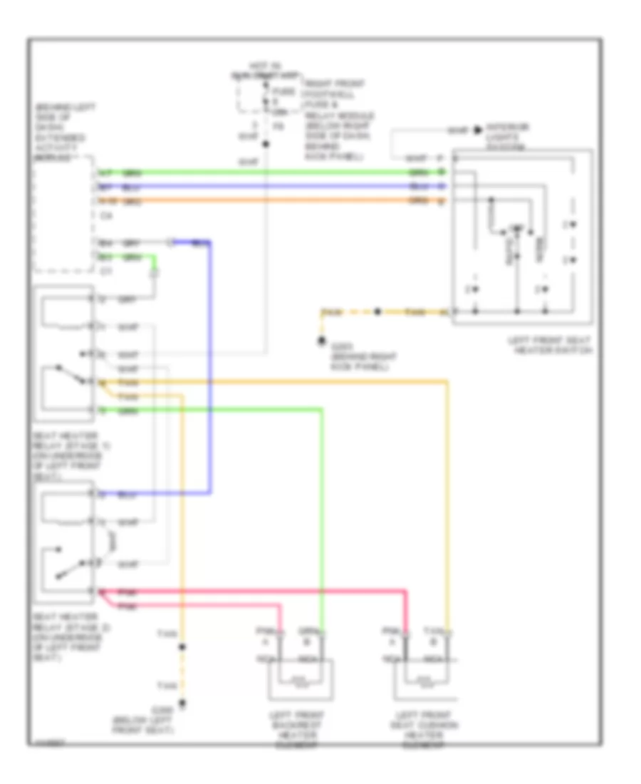
Driver Heated Seat Wiring Diagram for Mercedes-Benz ML430 2000
List of elements for Driver Heated Seat Wiring Diagram for Mercedes-Benz ML430 2000:
- (behind left side of dash) extended activity module
- A10
- Fuse 20a
- G203 (behind right kick panel)
- G300 (below left front seat)
- Hot in run or start
- Interior lights system
- Left front backrest heater element
- Left front seat cushion heater element
- Left front seat heater switch
- Nca
- Norm
- Off
- Pnk
- Rapid
- Relay module (below right side of dash, behind kick panel)
- Right front footwell fuse &
- Seat heater relay (stage 1) (on underside of left front seat)
- Seat heater relay (stage 2) (on underside of left front seat)
- Tan
Driver Power Seat Wiring Diagram for Mercedes-Benz ML430 2000
List of elements for Driver Power Seat Wiring Diagram for Mercedes-Benz ML430 2000:
- Aft
- Backrest
- Backrest fore/ aft motor
- Fore
- Front raise/ lower motor
- Front seat height
- Fuse 30a
- G300 (below left front seat)
- Hot in run or start
- Left front electric seat adjustment switch
- Lower
- Nca
- Pnk
- Raise
- Rear raise/ lower motor
- Rear seat height
- Relay module (below right side of dash, behind kick panel)
- Right front footwell fuse &
- S22x1
- Seat fore/ aft motor
- Seat fore/aft
- Tan
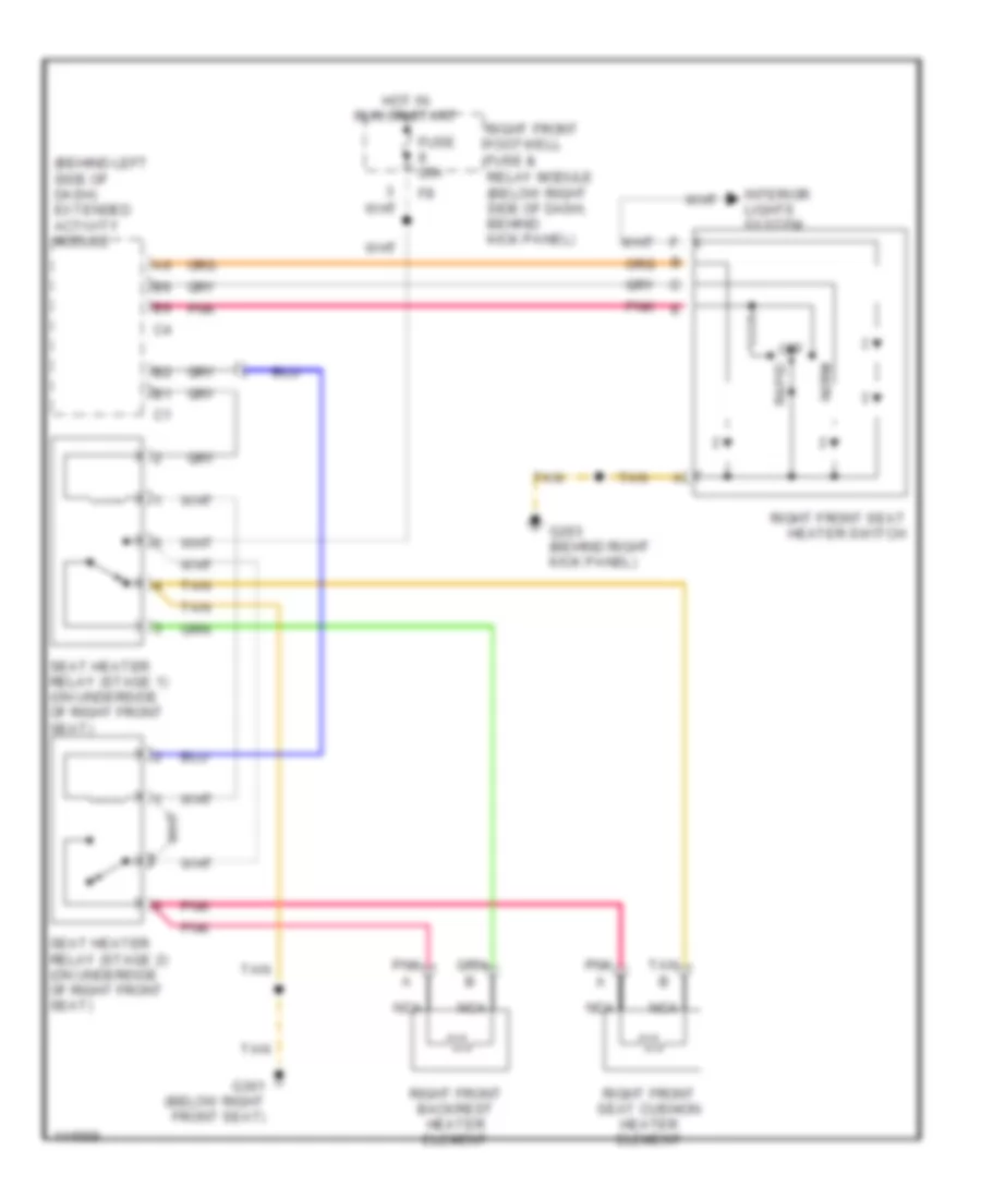
Passenger Heated Seat Wiring Diagram for Mercedes-Benz ML430 2000
List of elements for Passenger Heated Seat Wiring Diagram for Mercedes-Benz ML430 2000:
- (behind left side of dash) extended activity module
- Fuse 20a
- G203 (behind right kick panel)
- G301 (below right front seat)
- Hot in run or start
- Interior lights system
- Nca
- Norm
- Off
- Pnk
- Pnk e
- Rapid
- Relay module (below right side of dash, behind kick panel)
- Right front backrest heater element
- Right front footwell fuse &
- Right front seat cushion heater element
- Right front seat heater switch
- Seat heater relay (stage 1) (on underside of right front seat)
- Seat heater relay (stage 2) (on underside of right front seat)
- Tan
Passenger's Power Seat Wiring Diagram for Mercedes-Benz ML430 2000
List of elements for Passenger's Power Seat Wiring Diagram for Mercedes-Benz ML430 2000:
- Aft
- Backrest
- Backrest fore/ aft motor
- Fore
- Front raise/ lower motor
- Front seat height
- Fuse 30a
- G301 (below right front seat)
- Hot in run or start
- Lower
- Nca
- Pnk
- Raise
- Rear raise/ lower motor
- Rear seat height
- Relay module (below right side of dash, behind kick panel)
- Right front electric seat adjustment switch
- Right front footwell fuse &
- S23x1
- Seat fore/ aft motor
- Seat fore/aft
- Tan
POWER TOP/SUNROOF
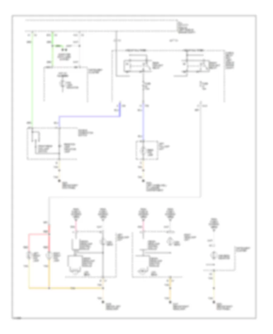
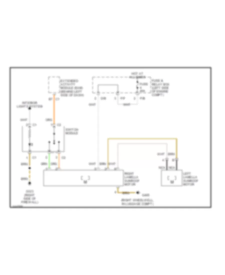
Double Panel Sunroof Wiring Diagram for Mercedes-Benz ML430 2000
List of elements for Double Panel Sunroof Wiring Diagram for Mercedes-Benz ML430 2000:
- (right wheelwell, in luggage compt)
- C1 b7
- D/b
- Extended activity module (eam) (behind left side of dash)
- Fuse & relay box (left side of engine compt)
- Fuse 40a
- G123 (right side of firewall)
- G405
- Hot at all times
- Interior lights system
- Left lamella sunroof motor
- Nca
- P/b
- P/f
- Right lamella sunroof motor
- Switch module
Single Panel Sunroof Wiring Diagram for Mercedes-Benz ML430 2000
List of elements for Single Panel Sunroof Wiring Diagram for Mercedes-Benz ML430 2000:
- C1 b7
- D/b
- Extended activity module (eam) (behind left side of dash)
- Fuse & relay box (left side of engine compt)
- Fuse 30a
- G123 (right side of firewall)
- Hot at all times
- Interior lights system
- P/b
- P/f
- Sliding/ pop-up roof drive assembly
- Switch module
POWER WINDOWS
Power Windows Wiring Diagram for Mercedes-Benz ML430 2000
List of elements for Power Windows Wiring Diagram for Mercedes-Benz ML430 2000:
- 0 off 1 close 2 open
- 0 off 1 close 2 open 3 exp down 4 lock 5 unlock
- 87a
- A11
- All activity module
- B10
- Center console switch group
- Convenience relay
- Fuse & relay box (left side of engine compt)
- Fuse 30a
- G300 (below left front seat)
- Hot at all times
- Left front power
- Left front power window motor
- Left front power window relay
- Left rear
- Left rear power window motor
- P/b
- P/d
- P/e
- Pnk
- Power window combination switch (rear center console)
- Power window switch
- Rear power windows safety switch
- Right front power
- Right front power window motor
- Right front power window relay
- Right rear
- Right rear power window motor
- Tan
- Window switch
- X35/3
- X35/4
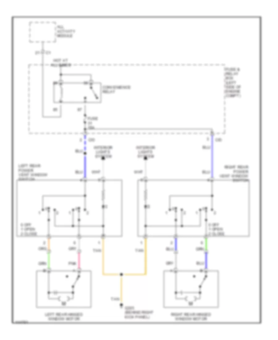
Rear Quarter Windows Wiring Diagram for Mercedes-Benz ML430 2000
List of elements for Rear Quarter Windows Wiring Diagram for Mercedes-Benz ML430 2000:
- 0 off 1 open 2 close
- All activity module
- C/d
- Convenience relay
- Fuse & relay box (left side of engine compt)
- Fuse 15a
- G203 (behind right kick panel)
- Hot at all times
- Interior lights system
- Left rear hinged window motor
- Left rear power vent window switch
- Pnk
- Right rear hinged window motor
- Right rear power vent window switch
- Tan
RADIO
Radio Wiring Diagrams, Premium Radio for Mercedes-Benz ML430 2000
List of elements for Radio Wiring Diagrams, Premium Radio for Mercedes-Benz ML430 2000:
- (below left side of dash) data link connector
- A10
- A11
- A12
- Acoustimass bass module (under driver's seat)
- Antenna splitter (on right side of liftgate)
- Audio amplifier (behind left side of dash)
- B10
- B11
- B12
- Cd changer
- Coax
- Defoggers system
- Esp/sps/bas control module (in left side of eng compt, in e box)
- Exterior lights system
- Fm/am amplifier (in liftgate, behind trim)
- Fuse & relay box
- Fuse 10 10a
- Fuse 21 25a
- G203 (behind right kick panel)
- G412 (center of hatch door)
- Hot at all times
- Hot in off, acc or run
- Interior lights system
- Left antenna coil
- Left front door speaker
- Left rear door speaker
- Nca
- P/b
- P/d
- Pnk
- Pnk a
- Radio
- Rear window defroster element
- Red
- Red b
- Restraint system control module
- Right antenna coil
- Right front door speaker
- Right rear door speaker
- Tan
- Telephone voltage c
Radio Wiring Diagrams, Standard for Mercedes-Benz ML430 2000
List of elements for Radio Wiring Diagrams, Standard for Mercedes-Benz ML430 2000:
- (below left side of dash) data link connector
- Antenna splitter (on right side of liftgate)
- Cd changer
- Coax
- Defoggers system
- Esp/sps/bas control module (in left side of eng compt, in e box)
- Exterior lights system
- Fm/am amplifier (in liftgate, behind trim)
- Fuse & relay box
- Fuse 10 10a
- Fuse 21 25a
- G203 (behind right kick panel)
- G412 (center of hatch door)
- Hot at all times
- Hot in off, acc or run
- Interior lights system
- Left antenna coil
- Left front door speaker
- Left rear door speaker
- Nca
- P/b
- P/d
- Pnk
- Pnk a
- Radio
- Rear window defroster element
- Red
- Red b
- Restraint system control module
- Right antenna coil
- Right front door speaker
- Right rear door speaker
- Tan
SHIFT INTERLOCKS
Shift Interlock Wiring Diagram for Mercedes-Benz ML430 2000
List of elements for Shift Interlock Wiring Diagram for Mercedes-Benz ML430 2000:
- C/b
- C/d
- C/f
- Can (+)
- Can (-)
- Can h
- Can l
- Circuit 15 relay (energized in run & start)
- Computer data lines system
- Data line
- Data link connector (dlc) (below left side of dash)
- Electronic selector lever control module (under center console, at base of selector lever assembly)
- Eps/sps/bas control module (in left side of engine compt, in "e" box)
- Etc control module (behind center of dash)
- Fuse & relay box (in left side of engine compt, in "e" box)
- Fuse 15a
- G203 (behind right kick panel)
- G300 (below left front seat)
- Ground
- Hot at all times
- Ignition
- P/c
- P/d
- Pnk
- Power
- Stoplamp sw
- Stoplamp switch (on brake pedal bracket)
- Tan
STARTING/CHARGING
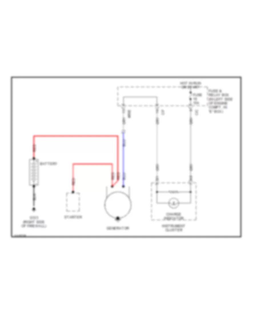
Charging Wiring Diagram for Mercedes-Benz ML430 2000
List of elements for Charging Wiring Diagram for Mercedes-Benz ML430 2000:
- Battery
- C/c
- C/f
- Charge indicator
- Fuse & relay box (in left side of engine compt, in "e" box)
- Fuse 15a
- G123 (right side of firewall)
- Generator
- Hot in run or start
- Instrument cluster
- Mr/e
- Red
- Starter
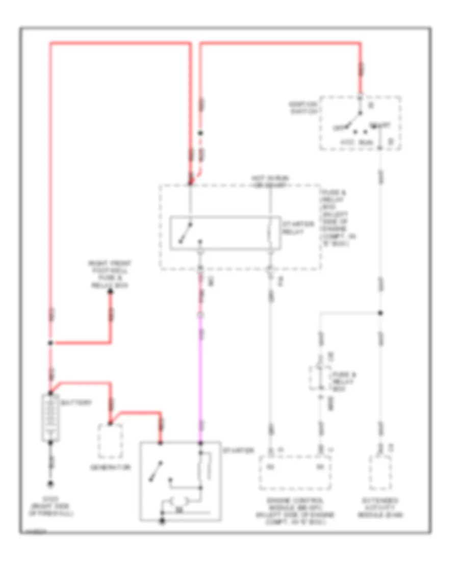
Starting Wiring Diagram for Mercedes-Benz ML430 2000
List of elements for Starting Wiring Diagram for Mercedes-Benz ML430 2000:
- Acc
- Battery
- C/e
- Engine control module (me-sfi) (in left side of engine compt, in "e" box)
- Extended activity module (eam)
- Fuse & relay box
- Fuse & relay box (in left side of engine compt, in "e" box)
- G123 (right side of firewall)
- Generator
- Hot in run or start
- Ignition switch
- M/c
- Mr/e
- Off
- P/a
- Pnk
- Red
- Right front footwell fuse & relay box
- Run
- Start
- Starter
- Starter relay
SUPPLEMENTAL RESTRAINTS
Supplemental Restraint Wiring Diagram, with Memory Seats (1 of 2) for Mercedes-Benz ML430 2000
List of elements for Supplemental Restraint Wiring Diagram, with Memory Seats (1 of 2) for Mercedes-Benz ML430 2000:
- (partial) (below left side of dash)
- 15r
- 2106 (or 3032)
- 3031 (or 3035)
- 3092 (or 3035)
- A11
- A15
- A18
- Air bag off indicator lamp
- All activity module (aam) (in left side of engine compartment in "e" box)
- Compartment, in e-box)
- Data link connector (dlc)
- Diagnosis
- Driver front ab squib
- Front passenger ab squib 1
- Fuse & relay box (in left side of engine compartment, in "e" box)
- Fuse 15a
- Fuse 7.5a
- Horn/ air bag clock spring contact
- Hot at all times
- Hot in off, acc or on
- Hot in on or start
- Instrument cluster
- Left door air bag squib
- Left esa control module (under left front seat)
- Left front seat belt buckle switch (in driver's seat belt buckle)
- Nca
- P/b
- P/c
- Pnk
- Red
- Right door air bag squib
- Right front footwell fuse & relay box (below right side of dash, behind kick panel)
- Seat belt reminder lamp
- Solid state
- Srs control module (below front of center console)
- Srs malfunction indicator lamp (mil)
- Tan
Supplemental Restraint Wiring Diagram, with Memory Seats (2 of 2) for Mercedes-Benz ML430 2000
List of elements for Supplemental Restraint Wiring Diagram, with Memory Seats (2 of 2) for Mercedes-Benz ML430 2000:
- (below center console) g302
- (passenger harness, under left front seat, near breakout for ground g300) z51/9
- (passenger tan harness, under center console in plastic harness channel) z53/9
- (under left front seat) g300
- 15r
- Front passenger seat occupied recognition w/automatic child seat recognition (ascr)
- Ground
- Left etr squib
- Left rear door air bag squib
- Left rear etr squib
- Left rear seat belt buckle/belt comfort feature switch
- Nca
- Pnk
- Right esa control module (under right front seat)
- Right etr squib
- Right front seat belt buckle switch (in passenger's seat belt buckle)
- Right rear door air bag squib
- Right rear etr squib
- Right rear seat belt buckle/belt comfort feature switch
- Signal
- Srs control module (below front of center console)
- Sw ground
- Tan
Supplemental Restraint Wiring Diagram, without Memory Seats (1 of 2) for Mercedes-Benz ML430 2000
List of elements for Supplemental Restraint Wiring Diagram, without Memory Seats (1 of 2) for Mercedes-Benz ML430 2000:
- (dlc) (partial) (below left side of dash)
- (passenger harness, under front of center console, near breakout for radio & srs control module) z52/15
- 15r
- 2106 (or 3032)
- 3031 (or 3035)
- 3092 (or 3035)
- A11
- A15
- A18
- Air bag off indicator lamp
- All activity module (aam) (in left side of engine compartment in "e" box)
- Data link connector
- Diagnosis
- Driver front ab squib
- Front passenger ab squib 1
- Fuse & relay box (in left side of engine compartment, in "e" box)
- Fuse 15a
- Fuse 7.5a
- Horn/ air bag clock spring contact
- Hot at all times
- Hot in off, acc or on
- Hot in on or start
- Instrument cluster
- Left door air bag squib
- Nca
- P/b
- P/c
- Pnk
- Red
- Right door air bag squib
- Right front footwell fuse & relay box (below right side of dash, behind kick panel)
- Seat belt reminder lamp
- Solid state
- Srs control module (below front of center console)
- Srs malfunction indicator lamp (mil)
- Z51/14 (passenger harness, left side of engine compartment, in e-box)
Supplemental Restraint Wiring Diagram, without Memory Seats (2 of 2) for Mercedes-Benz ML430 2000
List of elements for Supplemental Restraint Wiring Diagram, without Memory Seats (2 of 2) for Mercedes-Benz ML430 2000:
- (below center console) g302
- (passenger harness, under left front seat, near breakout for ground g300) z51/9
- (passenger harness, under right front seat, near breakout for ground g301) z52/1
- (passenger harness, under tan center console in plastic harness channel) z53/9
- (passenger tan harness, under center console in plastic harness channel) z53/9
- (under left front seat) g300
- (under right front seat) g301
- 15r
- Front passenger seat occupied recognition w/automatic child seat recognition (ascr)
- Ground
- Left etr squib
- Left front seat belt buckle/belt lock switch (in driver's seat belt buckle)
- Left rear door air bag squib
- Left rear etr squib
- Left rear seat belt buckle/belt comfort feature switch
- Nca
- Pnk
- Right etr squib
- Right front seat belt buckle/belt lock switch (in passenger's seat belt buckle)
- Right rear door air bag squib
- Right rear etr squib
- Right rear seat belt buckle/belt comfort feature switch
- Signal
- Srs control module (below front of center console)
- Sw ground
- Tan
TRANSMISSION
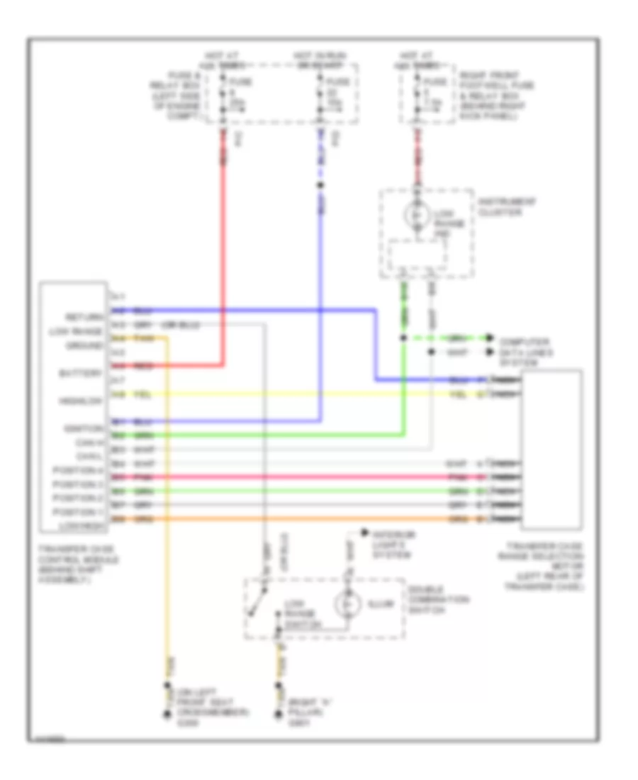
4WD Wiring Diagram for Mercedes-Benz ML430 2000
List of elements for 4WD Wiring Diagram for Mercedes-Benz ML430 2000:
- (on left front seat crossmember) g300
- (right "a" pillar) g901
- A11
- B10
- Battery
- Can h
- Can l
- Computer data lines system
- Double combination switch
- Fuse & relay box (left side of engine compt)
- Fuse 15a
- Fuse 25a
- Fuse 7.5a
- Ground
- High/low
- Hot at all times
- Hot in run or start
- Ignition
- Illum
- Instrument cluster
- Interior lights system
- Low range
- Low range ind
- Low range switch
- Low/high
- Nca
- P/c
- P/d
- Pnk
- Position 1
- Position 2
- Position 3
- Position 4
- Red
- Return
- Right front footwell fuse & relay box (behind right kick panel)
- Tan
- Transfer case control module (behind shift assembly)
- Transfer case range selection motor (left rear of transfer case)
A/T Wiring Diagram for Mercedes-Benz ML430 2000
List of elements for A/T Wiring Diagram for Mercedes-Benz ML430 2000:
- (on left front seat crossmember)
- 1-2/ 4-5 valve
- 1-2/4-5 vlv
- 2-3 shift valve
- 2-3 vlv
- 3-4 shift valve
- 3-4 vlv
- Backup sw out
- C/b
- C/d
- C/f
- Can (+)
- Can (-)
- Can h
- Can l
- Circuit 15 relay (energized in run & start)
- Computer data lines system
- Data line
- Data link connector (below left side of dash)
- Electronic selector lever control module (base of gear selector lever)
- Engine control module (left side of engine compt)
- Eps/sps/bas control module (left side of engine compt)
- Etc control module (behind center of dash)
- Exterior lights system
- Fuse & relay box (left side of engine compt)
- Fuse 15a
- G300
- G901 (right "a" pillar)
- Ground
- Hot at all times
- Ignition
- Illum
- Interior lights
- Kickdown sw
- Kickdown switch (top of accelerator pedal)
- Lock up valve
- Modul- ator valve
- Modulator vlv
- P/c
- P/d
- Pnk
- Power
- Pwm vlv
- Rpm 2
- Rpm 3
- Rpm sensor
- Sensor ground
- Sensor v+
- Shift valve
- Shift vlv
- Start interlock switch
- Stoplamp sw
- Stoplamp switch (on brake pedal bracket)
- Tan
- Temp sensor
- Temp/start
- Valve unit (electronic transmission control)
WIPER/WASHER
Front Wiper/Washer Wiring Diagram for Mercedes-Benz ML430 2000
List of elements for Front Wiper/Washer Wiring Diagram for Mercedes-Benz ML430 2000:
- (behind right headlamp) g107
- A12
- Acc
- All activity module (left side of engine compt)
- B12
- Battery
- C/b
- C/d
- C/f
- Can h
- Can l
- Combination switch
- Computer data lines system
- Extended activity module (eam) (behind left side of dash)
- Front wiper motor relay
- Fuse & relay box (left side of engine compt, in "e" box)
- Fuse 15a
- Fuse 30a
- G106 (behind left headlamp)
- G123 (right side of firewall)
- Ground
- Hot in off, acc or run
- Hot in run or start
- Ignition
- Ignition switch
- Int
- Ml/a
- Mr/a
- Mr/d
- Mr/e
- Off
- P/d
- Power distribution
- Rain sensor
- Red
- Run
- Start
- Tan
- Wash
- Washer switch
- Windshield washer pump
- Windshield wiper motor
- Wipe
- Wiper switch
Rear Wiper/Washer Wiring Diagram for Mercedes-Benz ML430 2000
List of elements for Rear Wiper/Washer Wiring Diagram for Mercedes-Benz ML430 2000:
- 470 ohm
- Acc
- All activity module (left side of engine compt)
- Battery
- C/b
- C/c
- C/d
- C/f
- Fuse & relay box (left side of engine compt, in "e" box)
- Fuse 10a
- Fuse 15a
- G106 (behind left headlamp)
- G123 (right side of firewall)
- G412 (center of tailgate)
- Hot in run or start
- Ignition switch
- Interior lights
- Ml/c
- Mr/b
- Mr/d
- Mr/e
- Off
- Pnk
- Power distribution
- Rear window washer pump
- Rear window wiper/ washer switch
- Red
- Right front footwell fuse & relay module (behind right kick panel)
- Run
- Start
- Tailgate window wiper motor
- Tan
- Wash