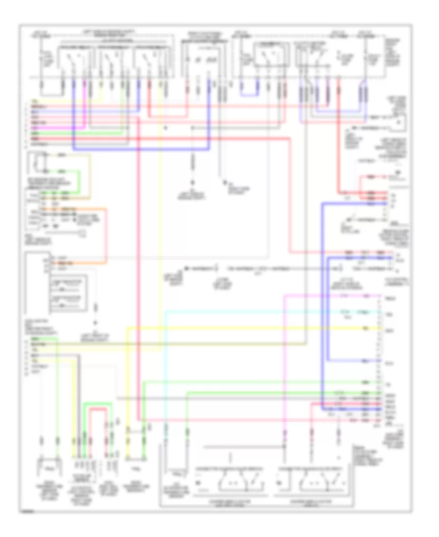
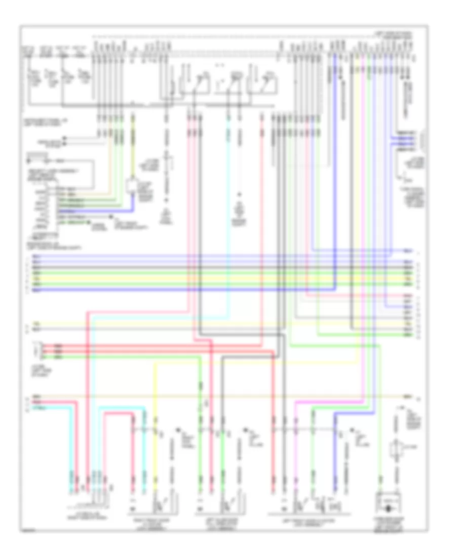
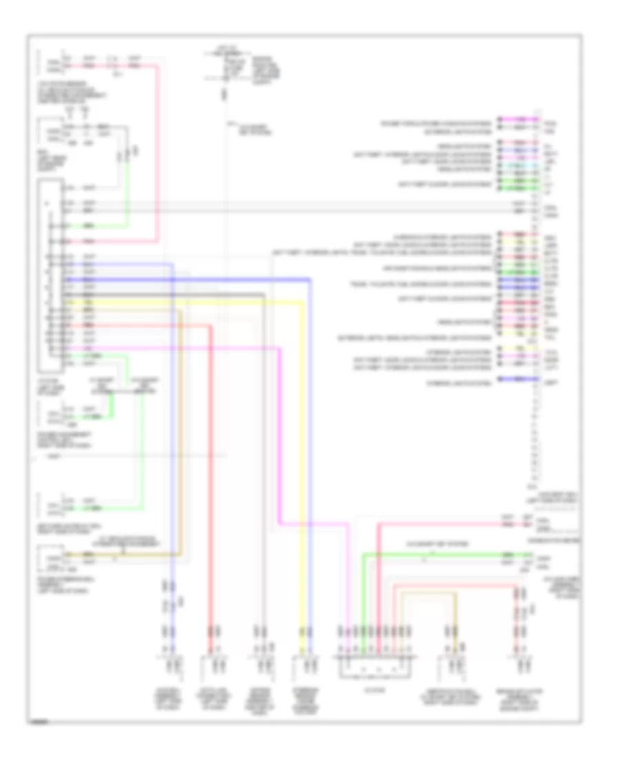
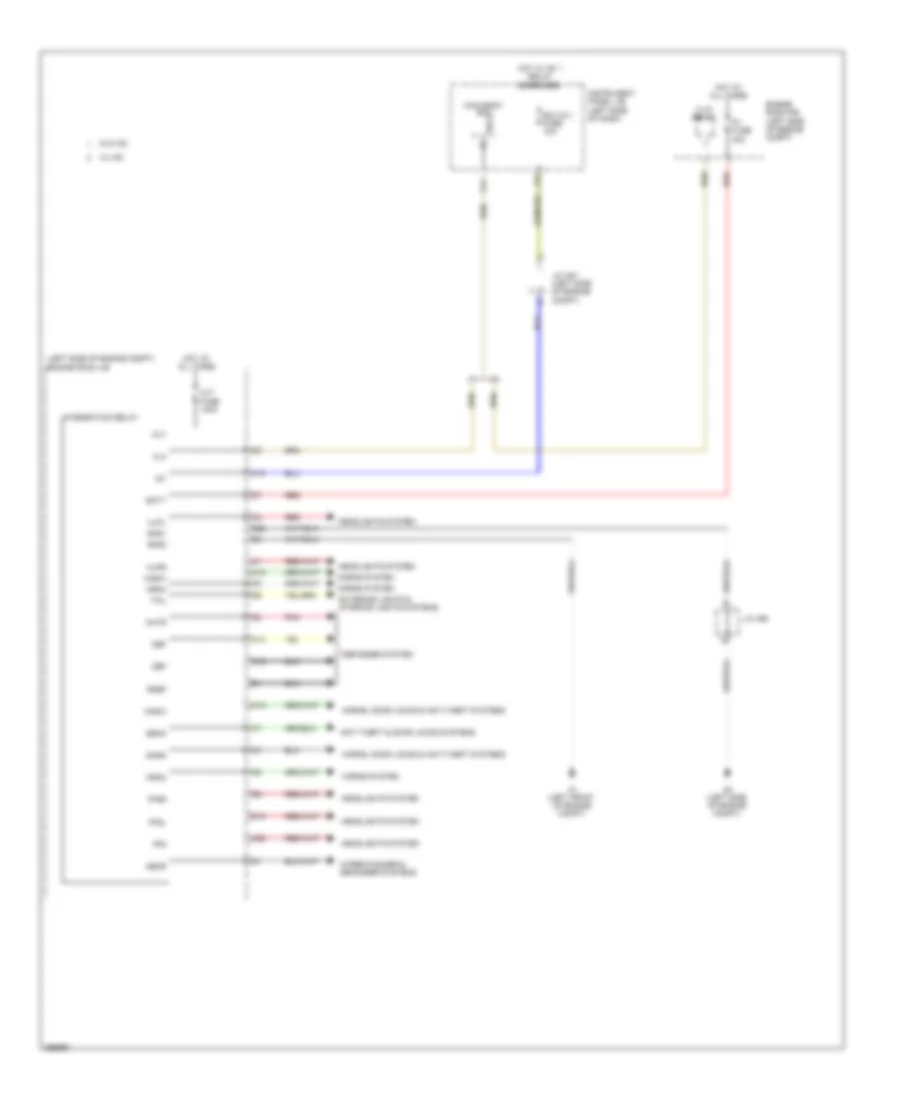
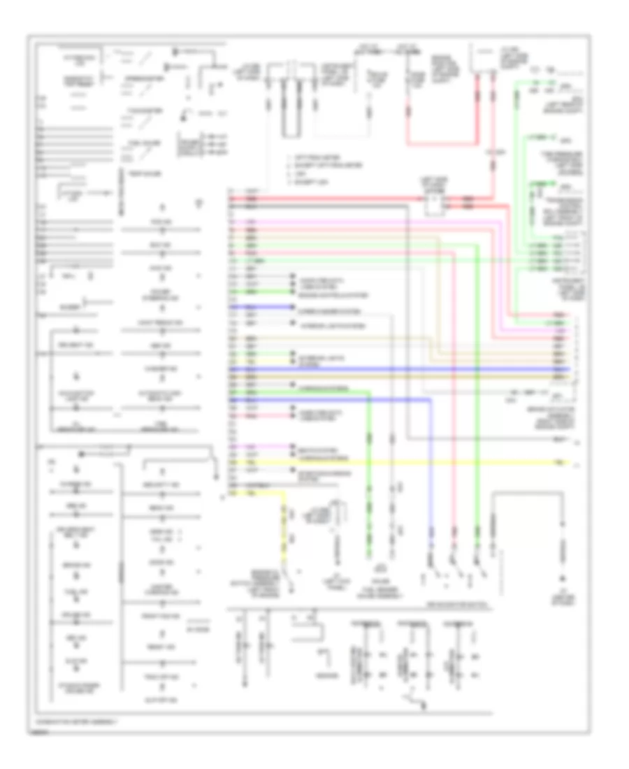
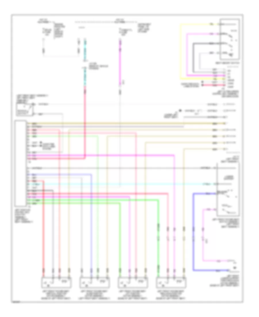
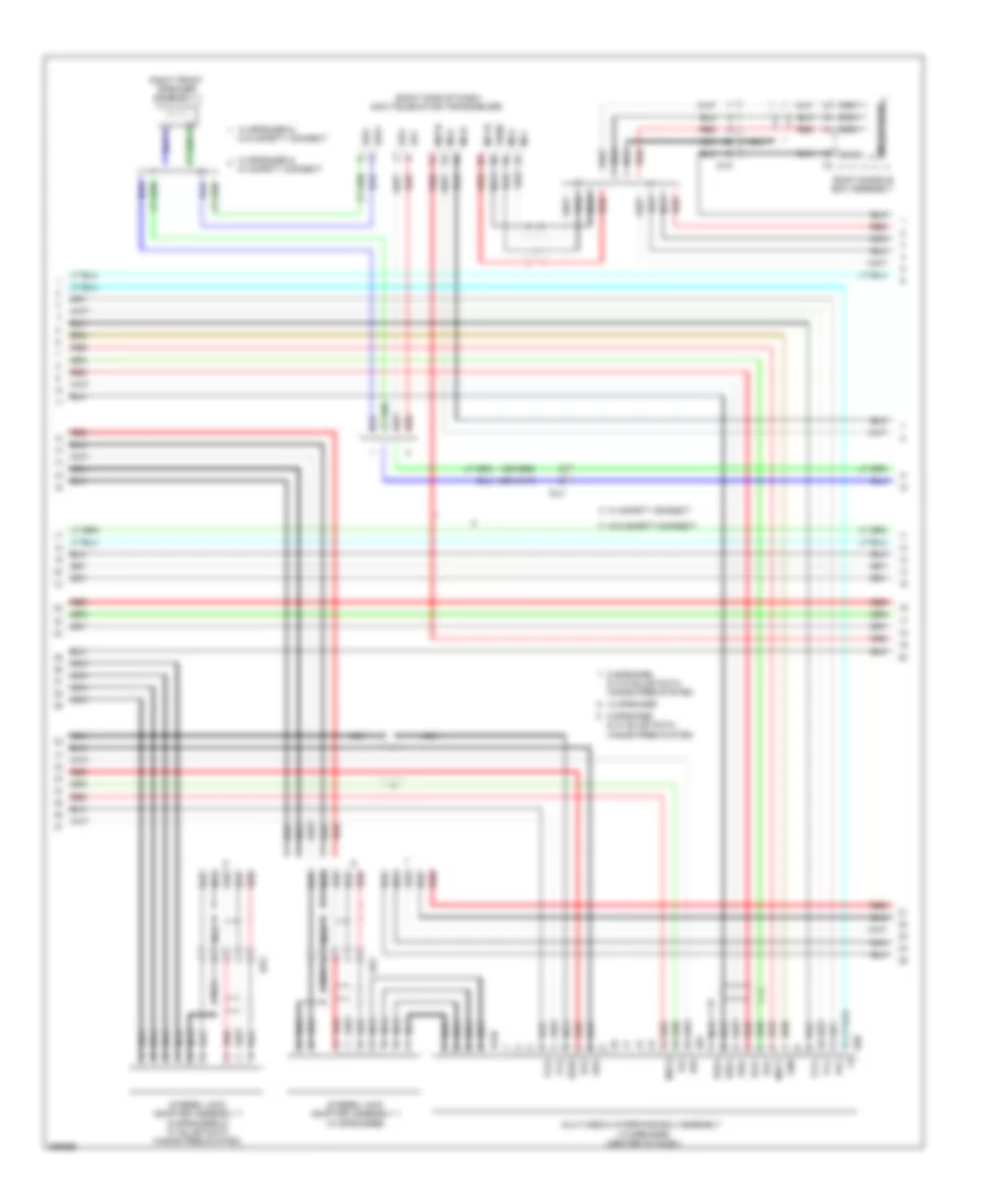
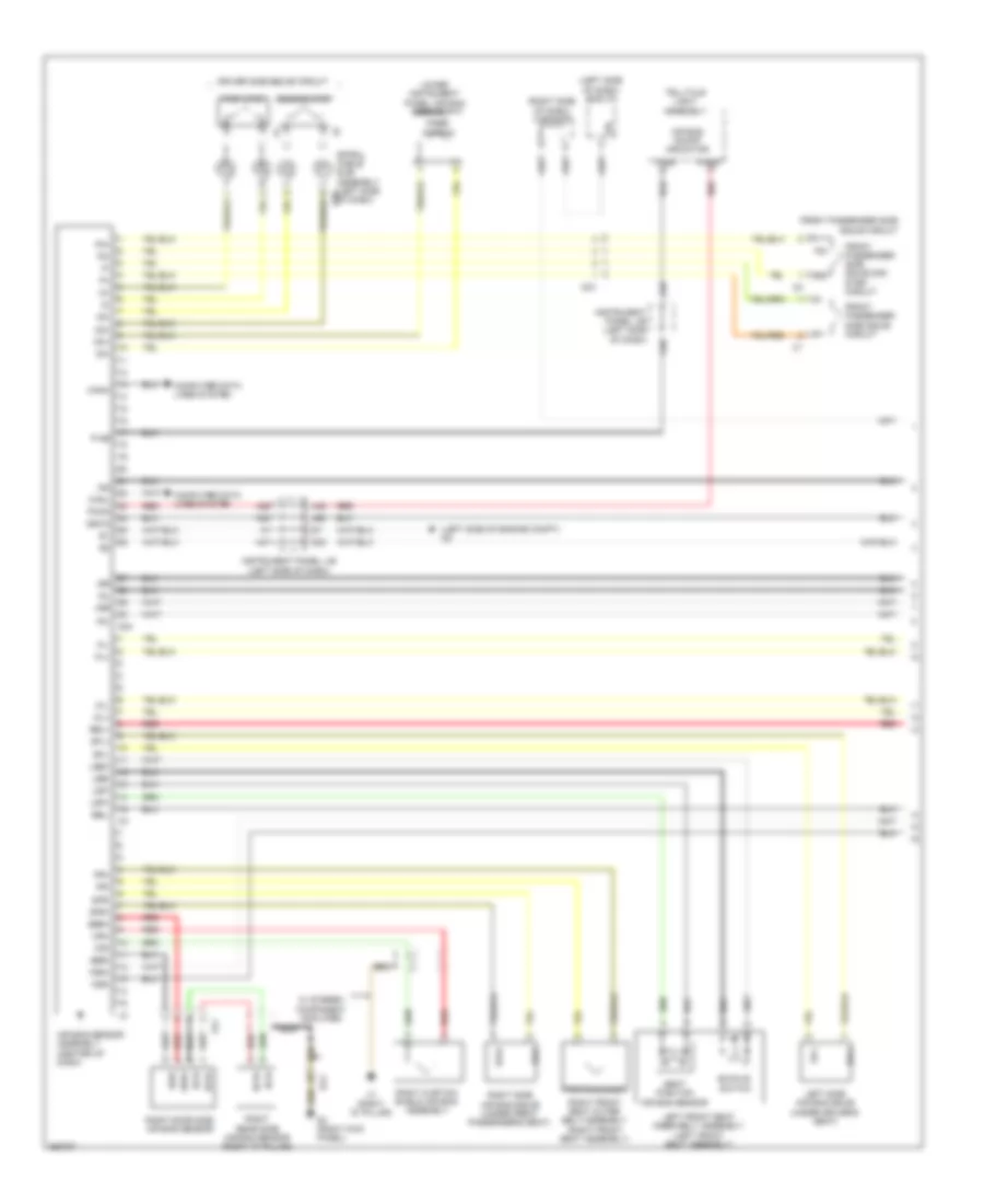
AIR CONDITIONING
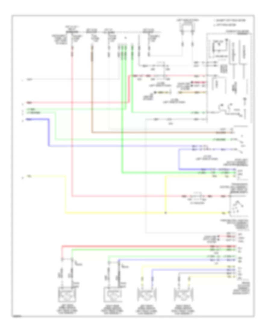
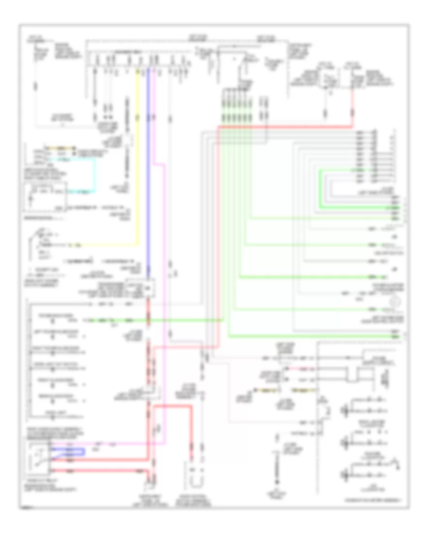
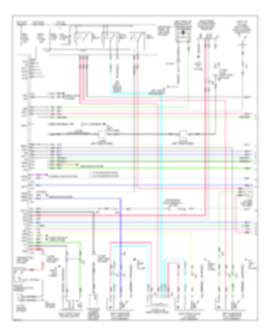
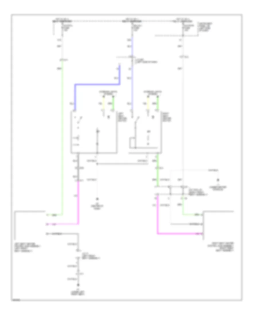
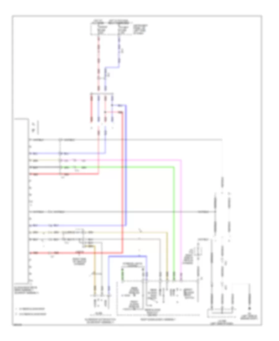
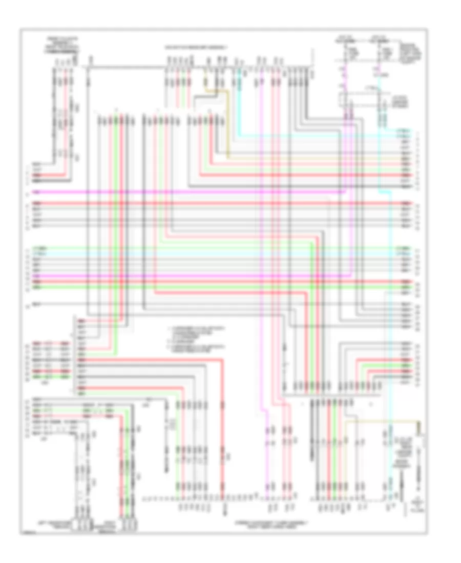
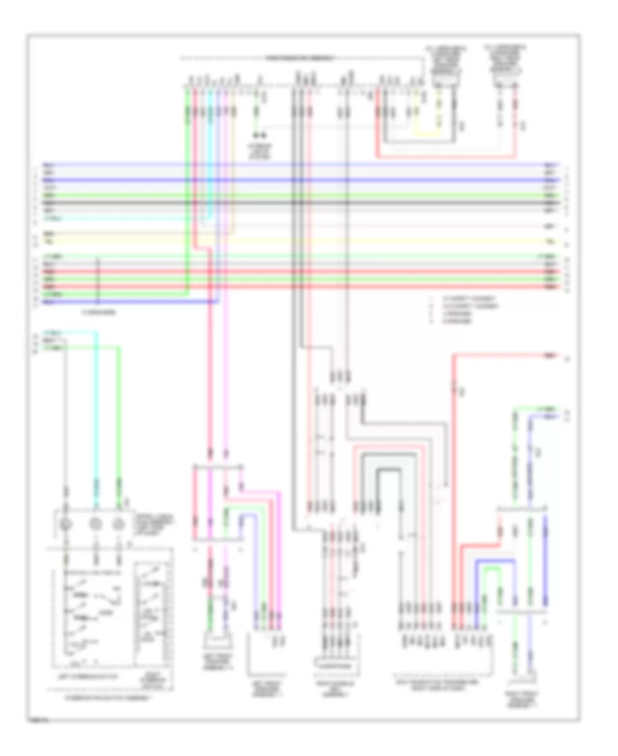
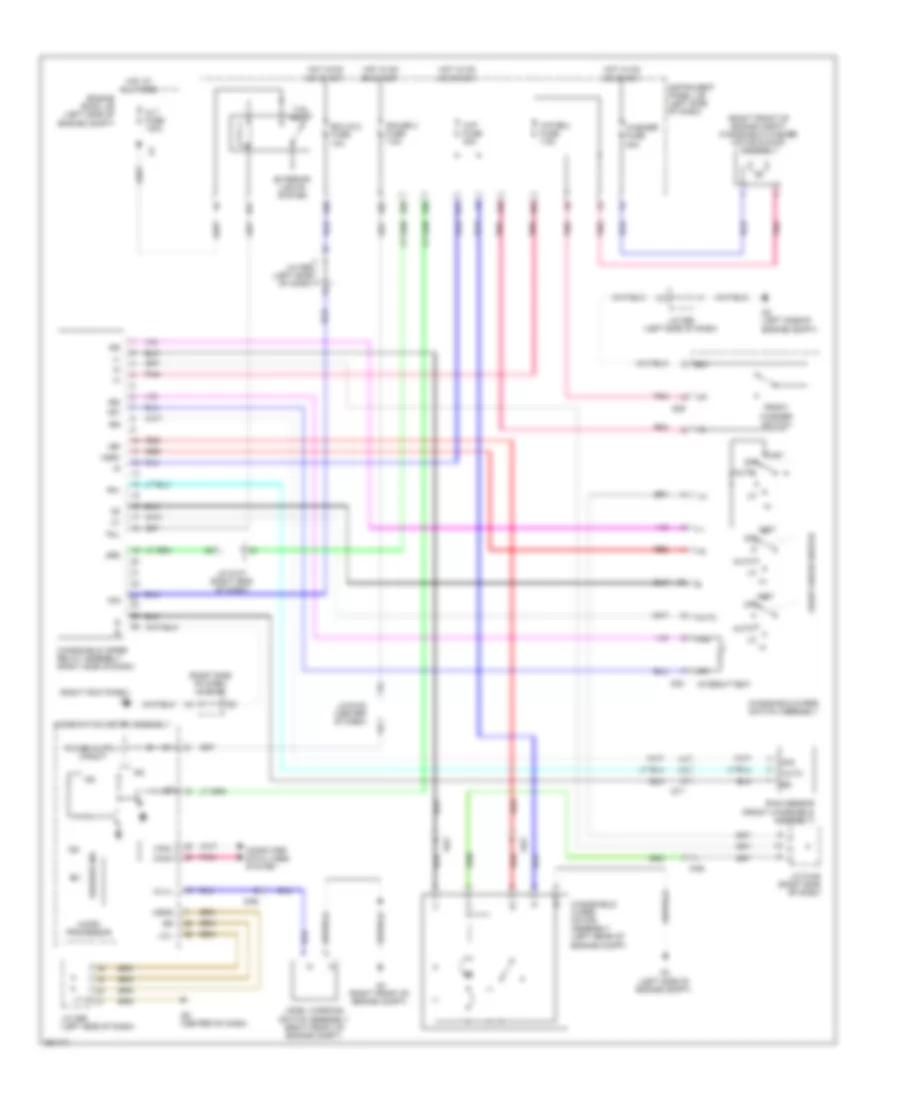
Automatic A/C Wiring Diagram (1 of 2) for Toyota Sienna 2013

List of elements for Automatic A/C Wiring Diagram (1 of 2) for Toyota Sienna 2013:
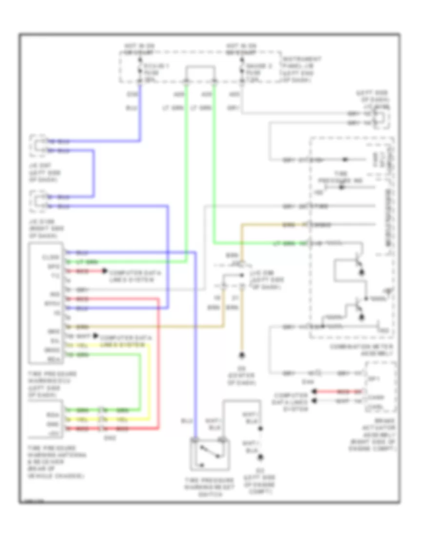
- A/c amplifier assembly (right side of dash)
- A/c control assembly
- A/c evaporator temperature sensor
- A/c pressure sensor (right front of engine compt)
- A1 (left front of engine compt)
- A54
- Ad3
- Ad4
- Alt
- Alt fuse 140a
- Ambient temperature sensor (front of engine compt)
- B bus
- B34
- B39
- B41
- Ba1
- Batt
- Blw
- Bus
- Bus g
- C14
- C16
- Canh
- Canl
- Compressor assembly (w/ pulley) (front of engine)
- Computer data lines system
- Connector housing color (black)
- Connector housing color (green)
- Connector housing color (red)
- D3 (right kick panel)
- D4 (right side of dash)
- D7 (center of dash)
- D75
- Da2
- Da4
- Damper servo motor (air inlet)
- Damper servo motor (air vent mode)
- Damper servo motor (left air mix)
- Damper servo motor (right air mix)
- Def
- Ecu-b fuse 7.5a
- Ed1
- Engine room j/b (left side of engine compt)
- Engine room r/b (left side of engine compt)
- F28
- Floq
- Front a/c blower assembly (right side of dash)
- Front blower w/ fan motor sub assembly (right side of dash)
- Front window deicer
- Gnd
- Gnd2
- Hot at all times
- Hot w/ ig1 2 relay energized
- Htr fuse 50a
- Htr-ig fuse 10a
- Ig+
- Ill+
- Ill-
- Instrument panel j/b (left side of dash)
- Integration relay
- Interior lights system
- J/c a51 (left side of engine compt)
- J/c a52 (left side of engine compt)
- J/c d106 (right side of dash)
- J/c d98 (left side of dash)
- Lin1
- Lock
- Mg+
- Mgc
- Mht
- Mhtr
- P/i fuse 40a
- Pnk
- Pre
- Ptc htr 2 fuse 30a
- Ptc htr 3 fuse 30a
- Ptc1
- Ptc2
- Ptc3
- Qufl
- Rdfg
- Red
- S5-1
- S5-3
- S5fl
- Sg-1
- Sg-2
- Sga
- Sgfl
- Sol+
- Sol-
- Ssr+
- Ssr-
- Starting/ charging system
- Switch
- Switch & rear window defogger
- Tam
- Tea
- Tsd
- Tsp
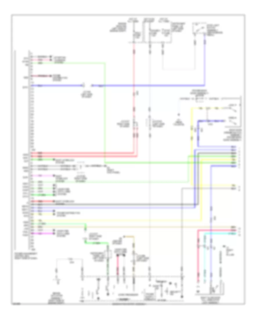
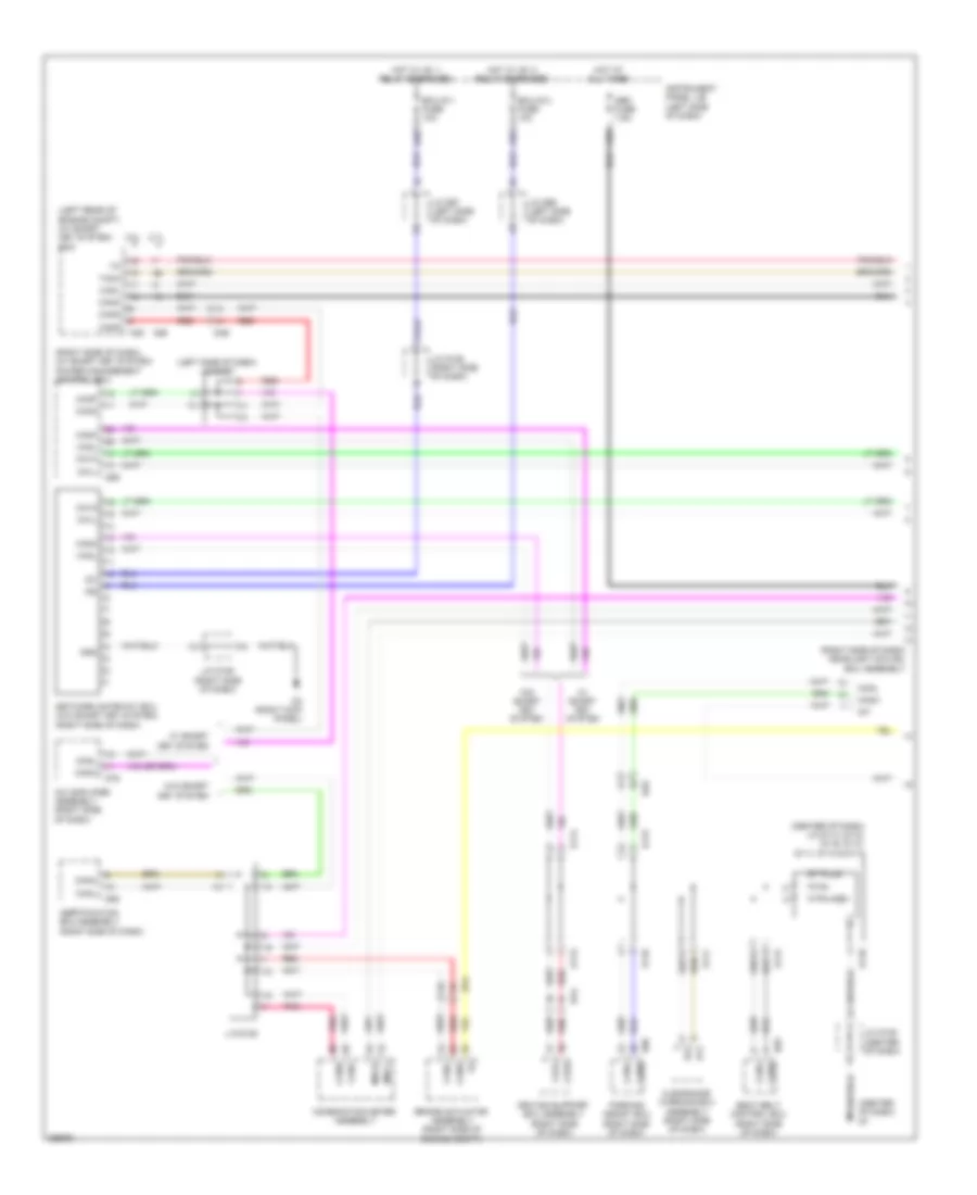
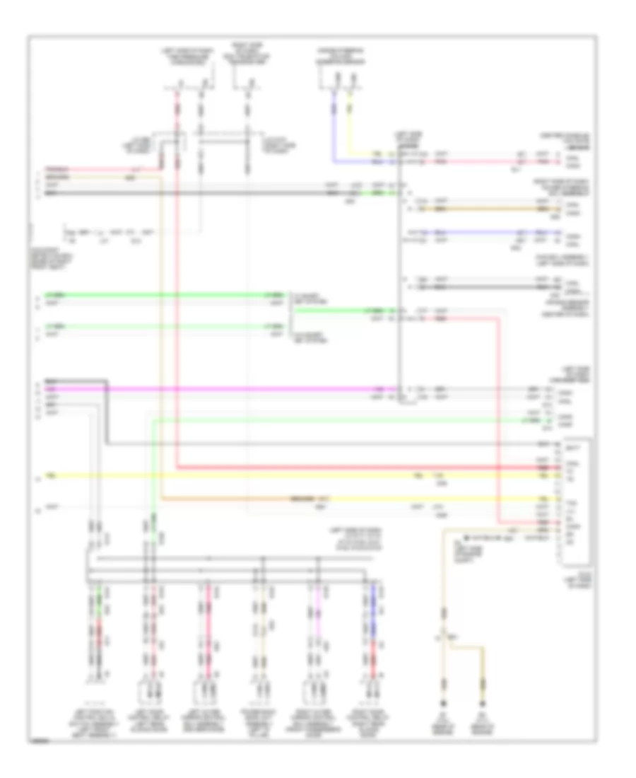
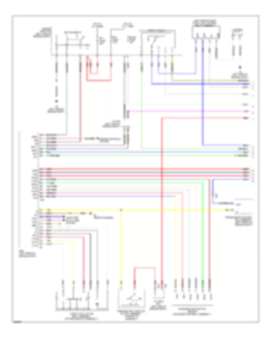
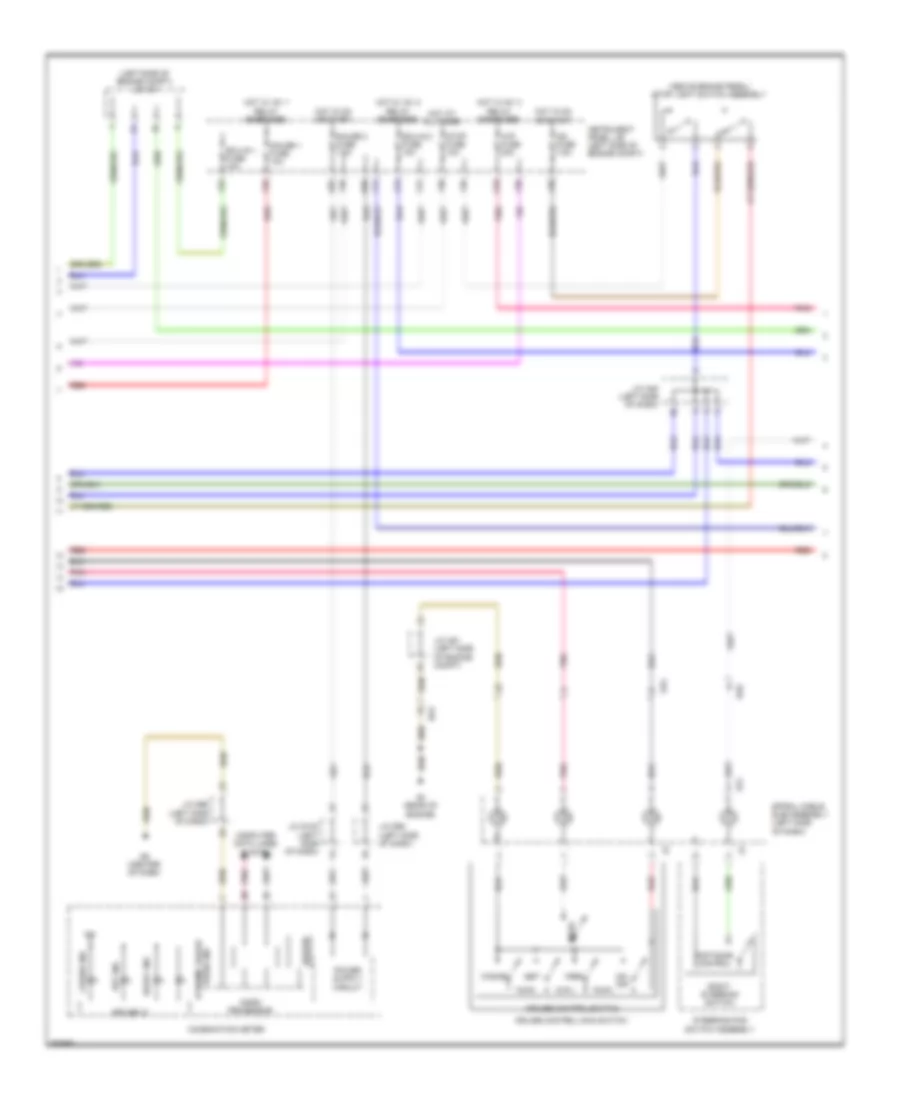
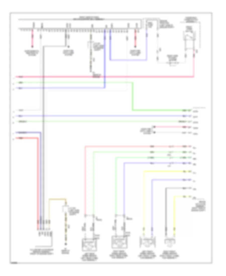
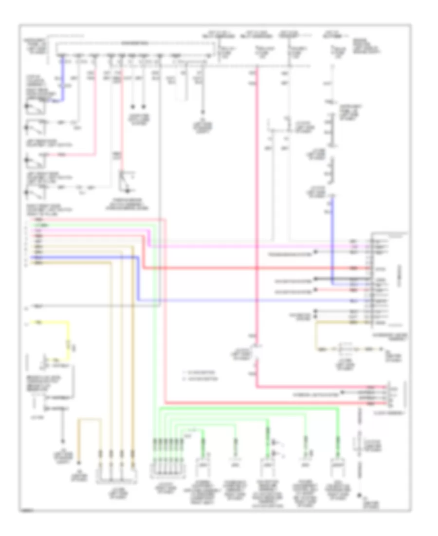
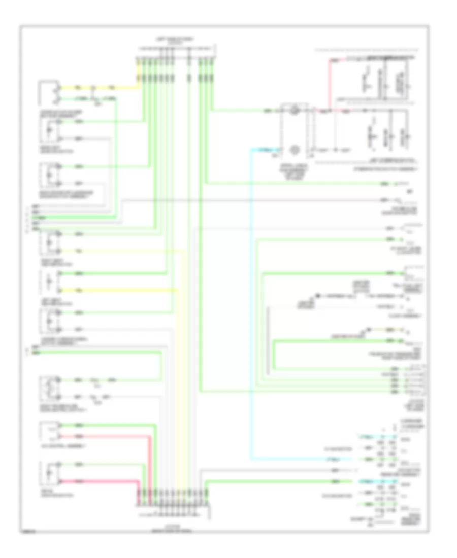
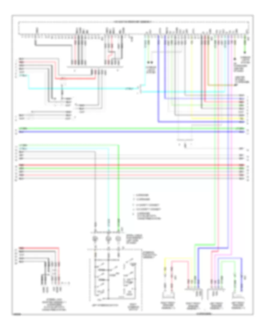
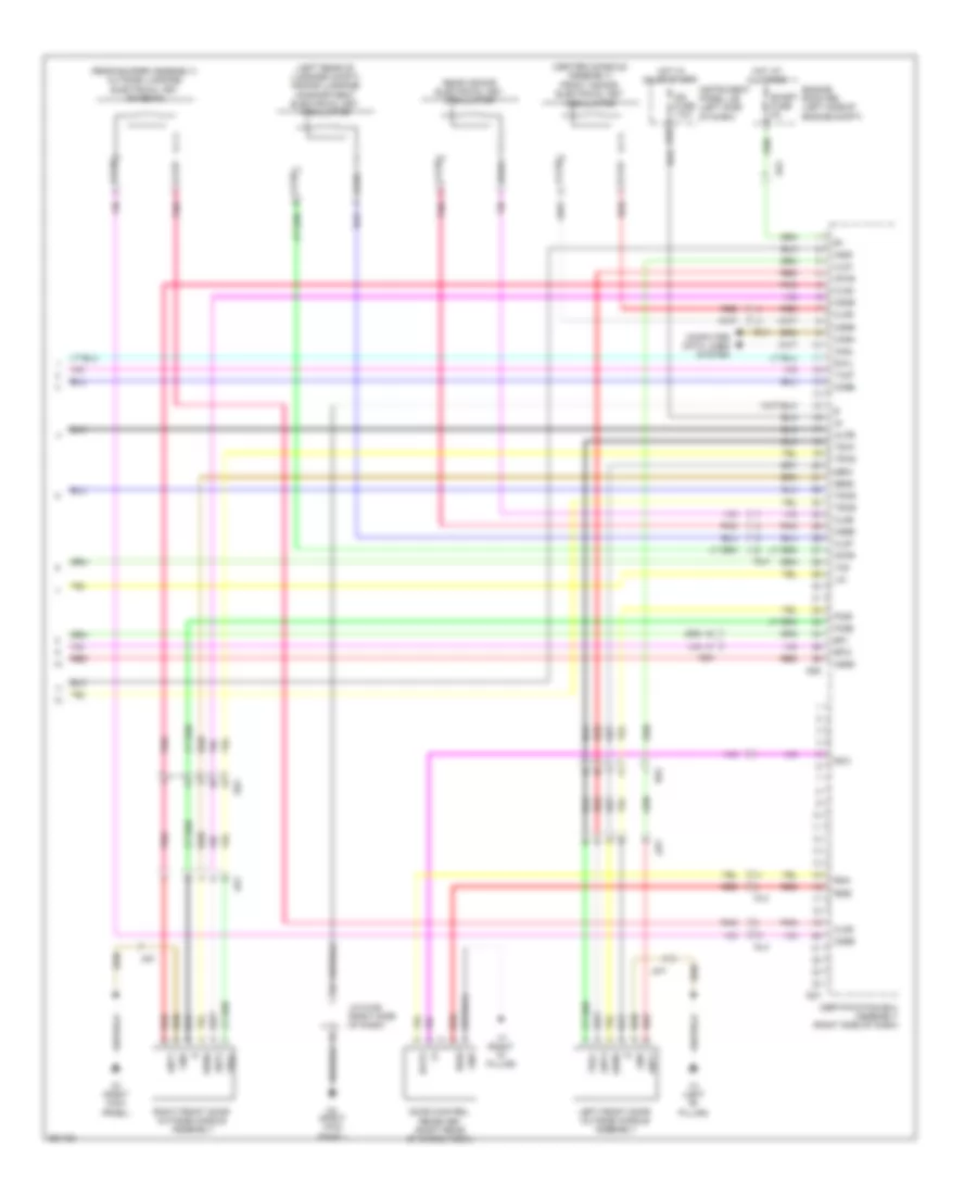
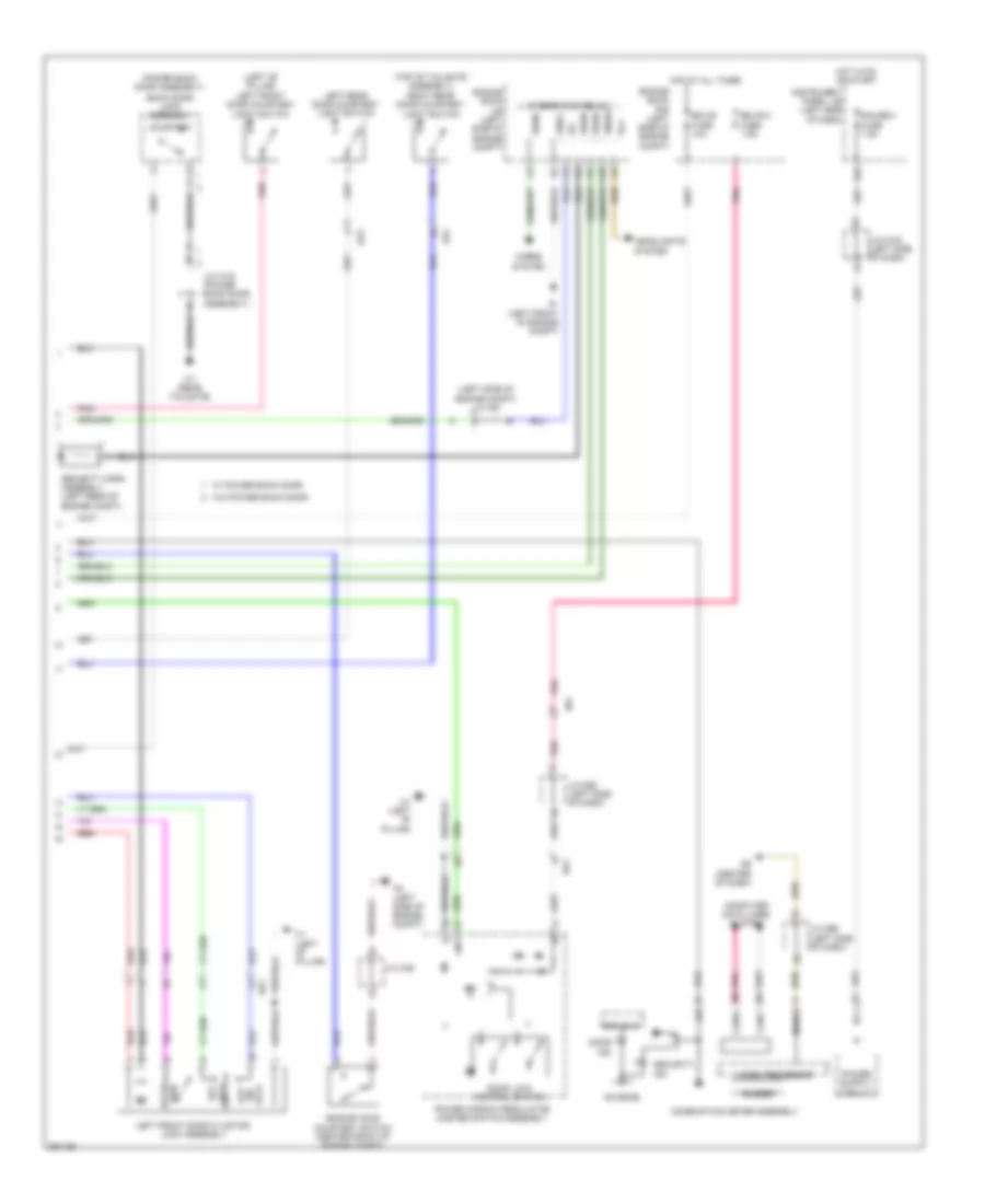
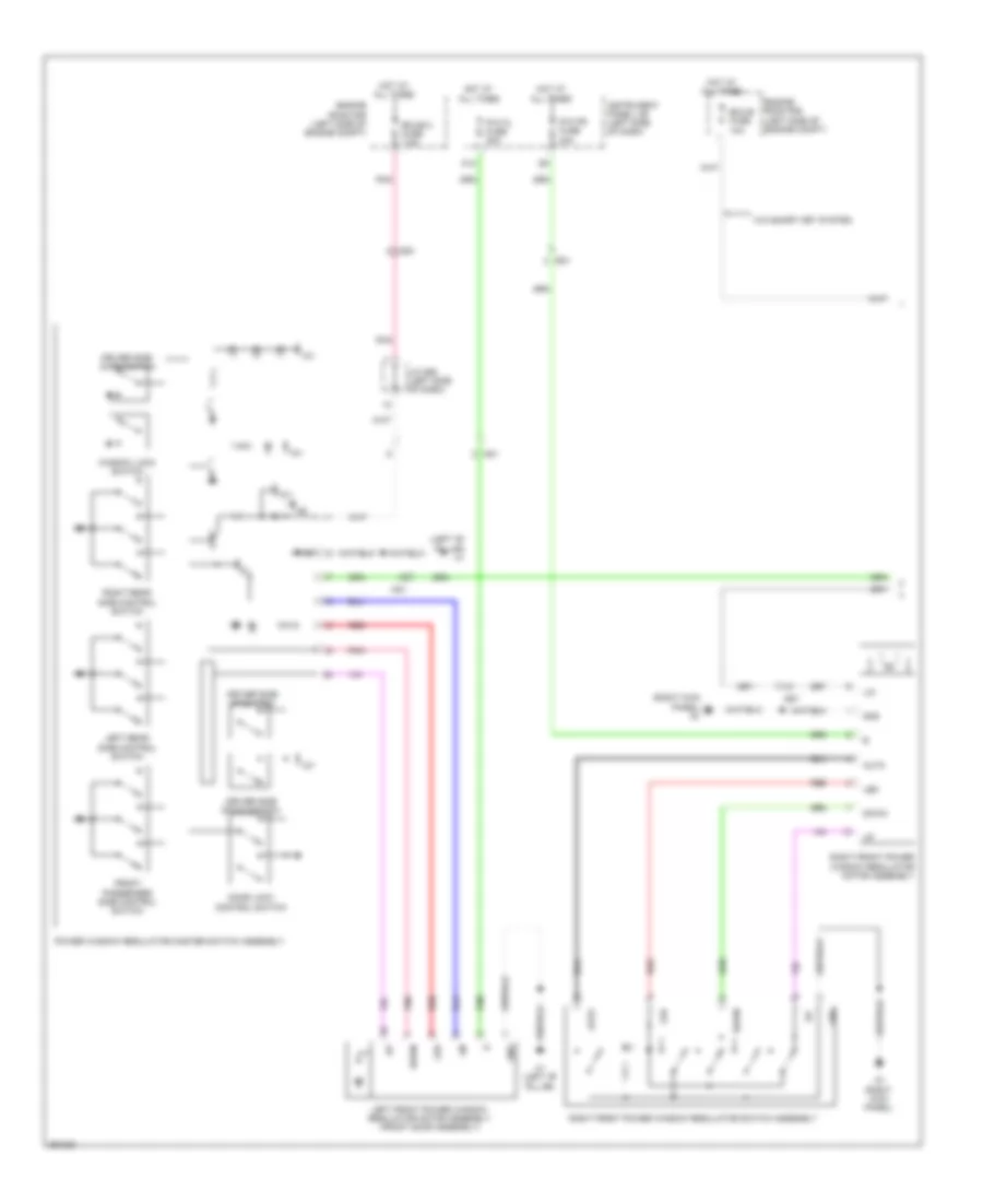
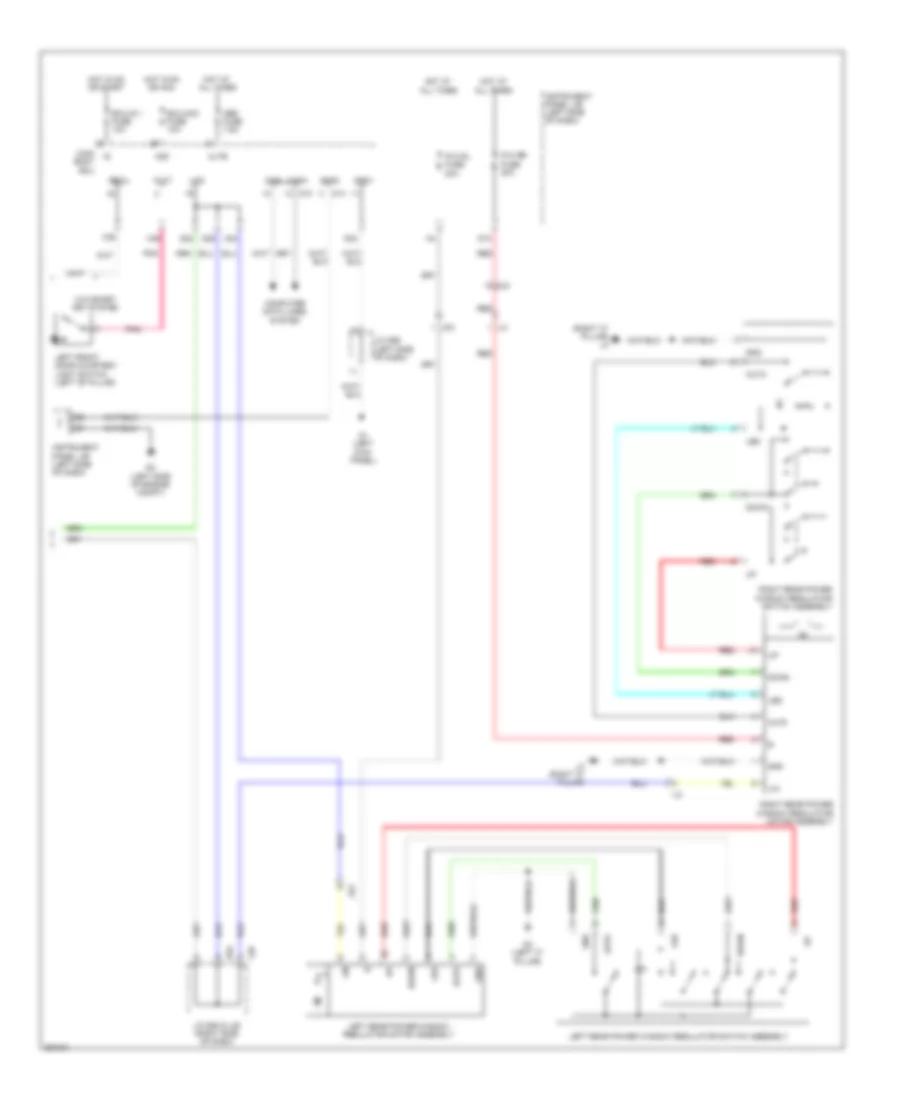
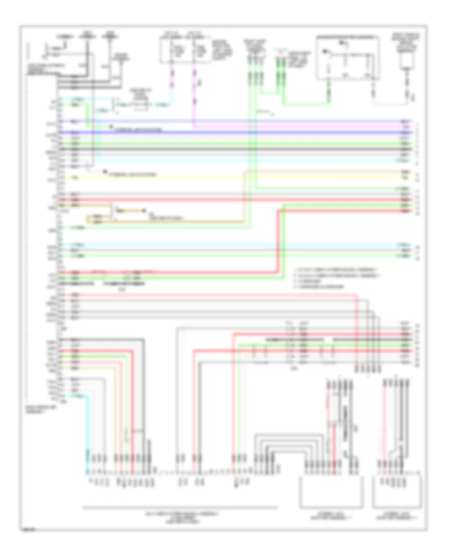
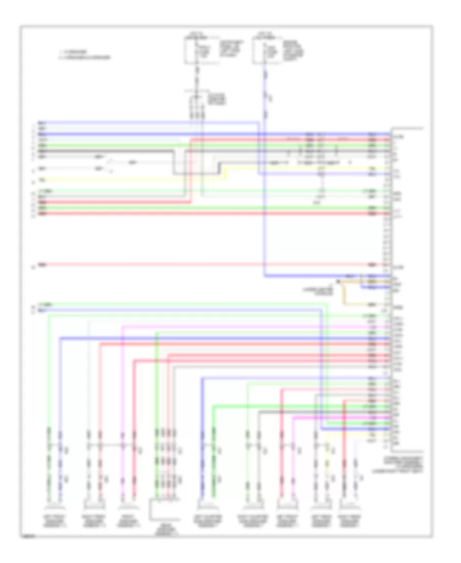
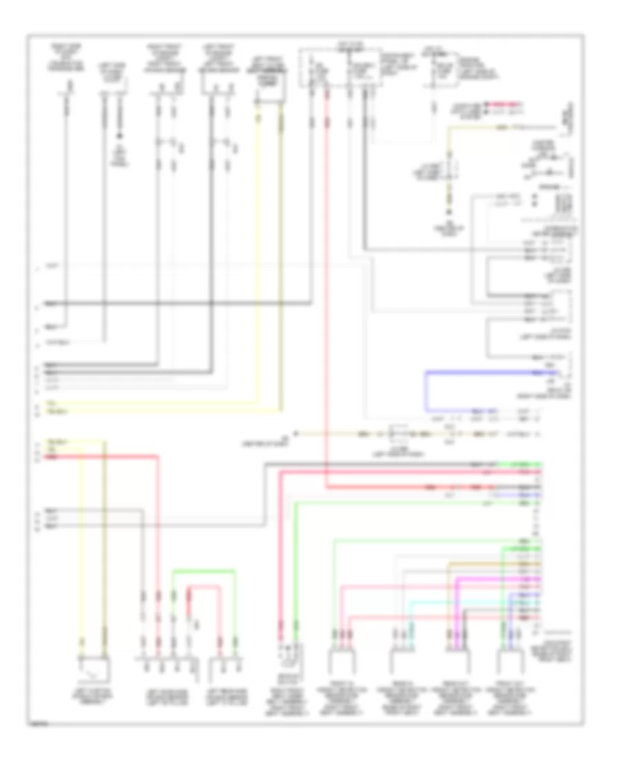
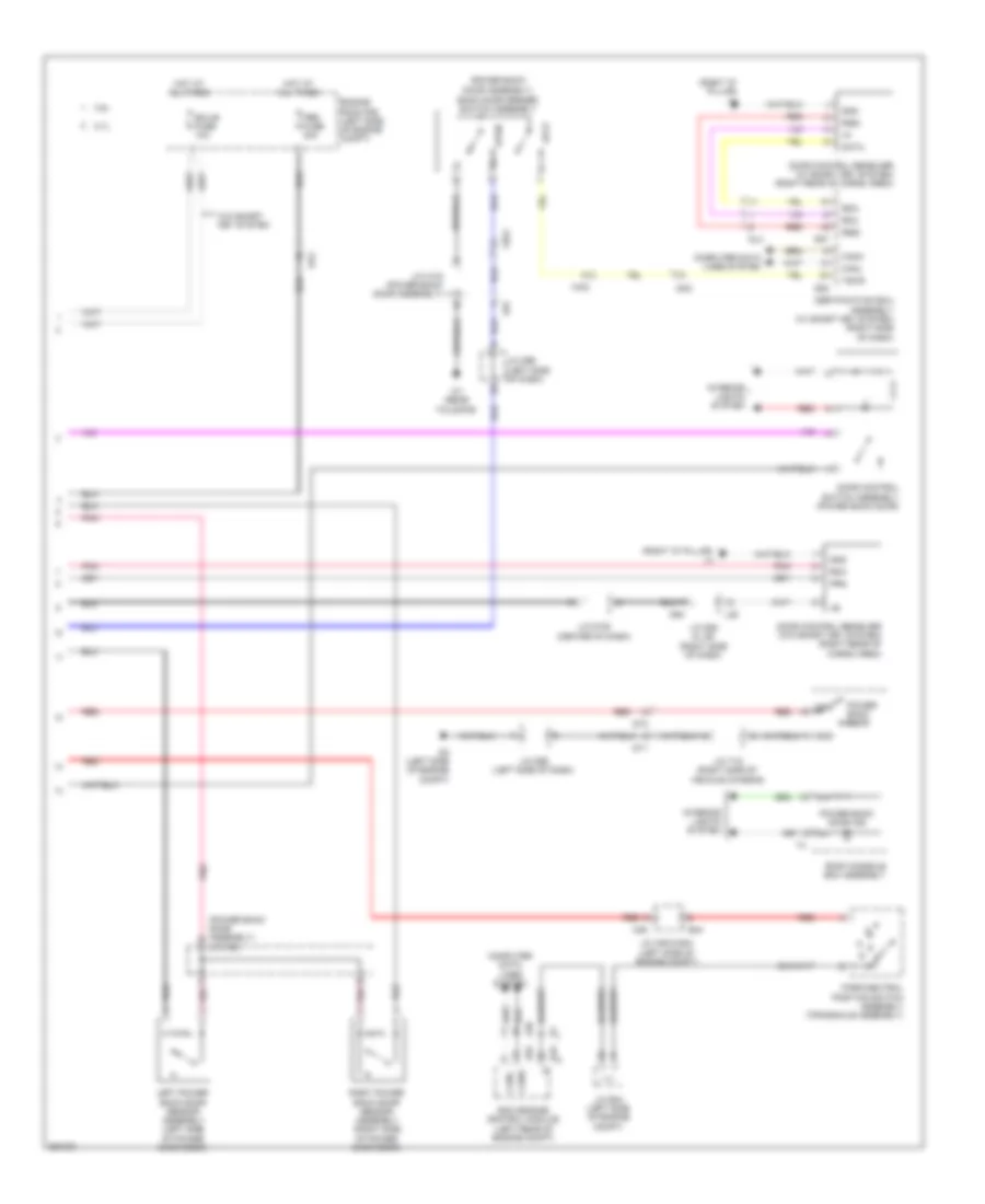
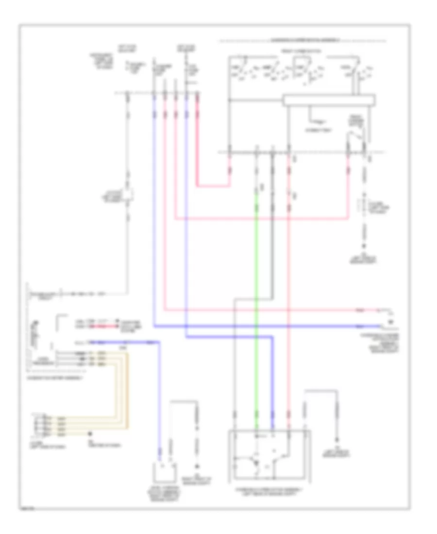
Automatic A/C Wiring Diagram (2 of 2) for Toyota Sienna 2013
List of elements for Automatic A/C Wiring Diagram (2 of 2) for Toyota Sienna 2013:
- (left rear of cargo area) rear blower w/ fan motor sub-assembly
- (left side of dash) diode (mg clt relay)
- (left side of engine compt) engine room r/b
- (right kick panel) (w/ ptc heater) quick heater assembly
- (w/ ptc heater)
- (w/o ptc heater) mg clt relay
- +b1
- +b2
- 2.7l
- 3.5l
- A/c amplifier assembly (right side of dash)
- A/c control assembly 2
- A/c evaporator temperature sensor
- A/c rr fuse 40a
- A/c solar sensor
- A1 (left front of engine compt)
- A2 (left side of engine compt)
- A39
- A5 (right side of dash)
- A53
- A54
- A55
- Automatic light control sensor (right side of dash)
- B45
- Blwh
- Canh
- Canl
- Cltb
- Clte
- Computer
- Connector housing color (brown)
- Connector housing color (gray)
- Cooling fan ecu (center front of engine compt)
- D13
- D2 (left side of engine compt)
- D74
- Damper servo motor (air mix)
- Damper servo motor (air vent mode)
- Data lines
- Dk3
- Dl3
- Dl4
- Dt1
- Ecm (left rear of engine compt)
- Ed1
- Efi engine coolant temperature sensor (rear of engine)
- Engine room r/b (left side of engine compt)
- Ethw
- Fan fuse 60a
- Fan relay
- Gnd
- Gnd2
- Hot at all times
- J/c d95 (left side of dash)
- J/c t15 (right side of vehicle chassis)
- L3 (right "d" pillar)
- La1
- Main body ecu (left side of dash)
- Main fan motor
- Mg clt fuse 7.5a
- Pnk
- Ptc htr 1 fuse 50a
- Ptc htr1 relay
- Ptc htr2 relay
- Ptc htr3 relay
- Rbbu
- Rbug
- Rbus
- Rear a/c blower assembly (right rear of cargo area)
- Rear blower motor control (right rear of cargo area)
- Red
- Rfc
- Rlin
- Room temperature sensor (left side of dash)
- Room temperature sensor 2
- Sg-6
- Sgnd
- Sub fan motor
- System
- Tec
- Thw
- Tsl
- Tsr
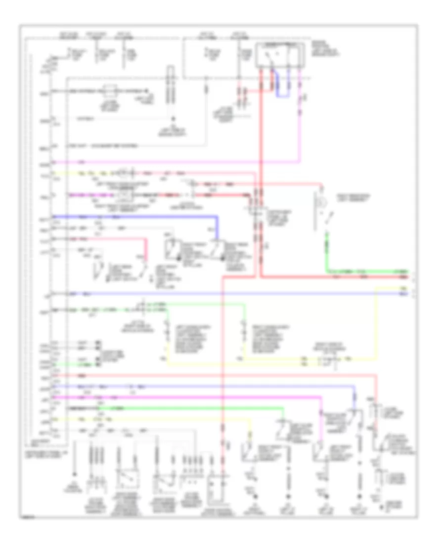
ANTI-LOCK BRAKES
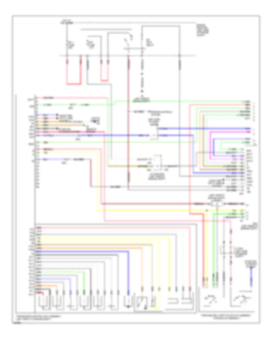
Anti-lock Brakes Wiring Diagram (1 of 2) for Toyota Sienna 2013
List of elements for Anti-lock Brakes Wiring Diagram (1 of 2) for Toyota Sienna 2013:
- (2wd)
- (awd)
- (left side of dash) skid control buzzer assembly
- (left side of engine compt) engine room r/b
- (left side of engine compt) j/c a51
- (right front of engine compt) a4
- +bs
- A2 (left side of engine compt)
- A4 (right front of engine compt)
- Brake actuator assembly (right side of engine compt)
- Brake pedal load sensing switch
- Buzzer
- Canh
- Canl
- Computer data lines system
- Csw
- D2 (left side of engine compt)
- Da6
- Dlc 3 (left side of dash)
- Ecu-b fuse 10a
- Ecu-ig 1 fuse 10a
- Engine room r/b (left side of engine compt)
- F18
- F29
- F30
- F31
- F32
- F33
- Fl+
- Fl-
- Fr+
- Fr-
- Fsw+
- Gnd
- Gnd1
- Gnd2
- Hot at all times
- Hot in on or start
- Ig1
- Instrument cluster system
- Instrument panel j/b (left side of dash)
- Interior lights system
- J/c a48 (left side of dash)
- J/c a49
- Ka2
- La1
- Left front speed sensor (left front wheel hub assembly)
- Left rear speed sensor (left rear wheel hub assembly)
- Out
- Pnk
- Red
- Right front speed sensor (right front wheel hub assembly)
- Right rear speed sensor (right rear wheel hub assembly)
- Rl+
- Rl-
- Rr+
- Rr-
- Sp1
- Stop fuse 10a
- Stop light control relay assembly (left side of dash)
- Stop light switch assembly (above brake pedal)
- Stop lp relay (w/ dynamic radar cruise control)
- Stp
- Stp1
- Stp2
- Stpo
- Vehicle stability control off switch
- Vsc 1 fuse 50a
- Vsc 2 fuse 30a
- Kl1
- Nk1
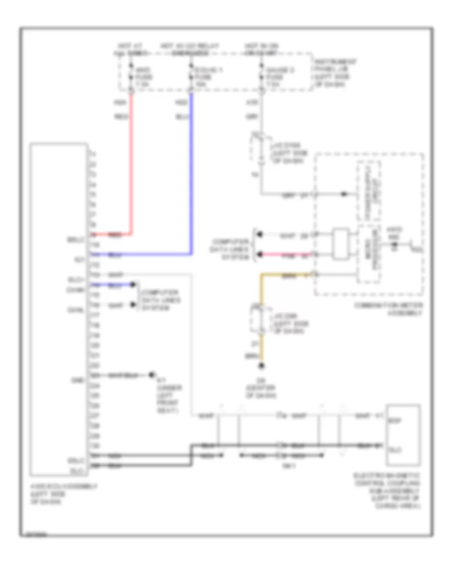
Anti-lock Brakes Wiring Diagram (2 of 2) for Toyota Sienna 2013
List of elements for Anti-lock Brakes Wiring Diagram (2 of 2) for Toyota Sienna 2013:
- (center of dash) j/c d105
- (left kick panel) d1
- (left side of dash) j/c d99
- (right side of dash) j/c d94 & l36
- (under center console) l1
- A2 (left side of engine compt)
- A55
- Abs ind
- Ad3
- Altb
- B/le
- Bat
- Brake fluid level warning switch (brake master cylinder reservoir assembly) (brake fluid reservoir)
- Brake ind
- Canh
- Canl
- Combination meter assembly
- Computer data lines system
- D13
- D32
- D36
- D38
- D49
- D6 (center of dash)
- D7 (center of dash)
- Drive ic
- Ecu-ig 1 fuse 10a
- Ess
- F16
- F39
- Gauge 2 fuse 7.5a
- Gnd
- Gnd1
- Hot at all times
- Hot in on or start
- Ig+
- Ig2
- Instrument panel j/b (left side of dash)
- J/c a49
- J/c d100 (left side of dash)
- J/c d96 (left side of dash)
- J/c d97 (left side of dash)
- J/c d98 (left side of dash)
- J/c l40 (right front seat assembly)
- L36
- Lcl-
- Main body ecu
- Micro processor
- Obd fuse 7.5a
- Parking brake switch assembly (parking brake lever)
- Pkb
- Pnk
- Slip ind
- Slip off ind
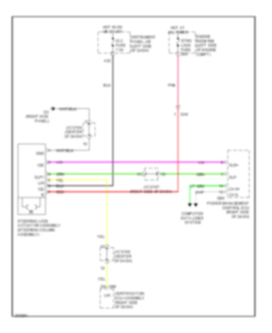
- Steering sensor (inside steering column)
- Trac off ind
- Yaw rate sensor (w/ vehicle dynamics integrated management) (center console)
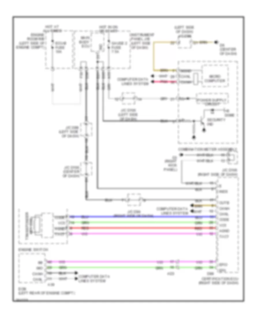
ANTI-THEFT
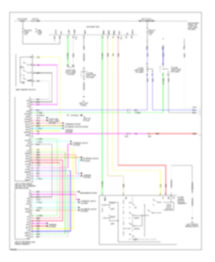
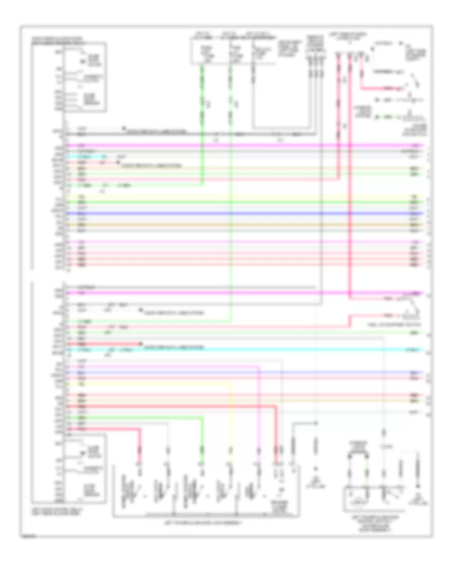
Forced Entry Wiring Diagram, with Smart Key System (1 of 4) for Toyota Sienna 2013
List of elements for Forced Entry Wiring Diagram, with Smart Key System (1 of 4) for Toyota Sienna 2013:
- (power back door assembly) j/c w19
- +b dome
- A28
- A30
- A35
- A55
- Accd
- Ad3
- Am2 2 fuse 7.5a
- Am21
- Am22
- Back door opener switch assembly (power back door assembly)
- Brake actuator assembly (right side of engine compt)
- Buzzer
- Ca1h
- Ca1l
- Ca2h
- Ca2l
- Ca3n
- Ca3p
- Canh
- Canl
- Combination meter assembly
- Computer data lines system
- D3 (right kick panel)
- D6 (center of dash)
- D89
- Da4
- Dk1
- Dk2
- Dl6
- Door ind
- Drive ic
- Engine room r/b (left side of engine compt)
- F29
- Gauge 2 fuse 7.5a
- Gnd
- Gnd2
- Hot at all times
- Hot in on or start
- Ig+
- Ig1d
- Ig2
- Ig2d
- Il2
- Il3
- Inds
- Indw
- Instrument panel j/b (left side of dash)
- J/c a48 (left side of dash)
- J/c d100 (left side of dash)
- J/c d106 (right side of dash)
- J/c d107 (right side of dash)
- J/c d96 (left side of dash)
- L2 (right "c" pillar)
- Lin2
- Lock
- Mgnd
- Micro processor
- Open
- Pnk
- Power distribution system
- Power management control ecu (right side of dash)
- Red
- Right slide door full open stop lock assembly
- Security ind
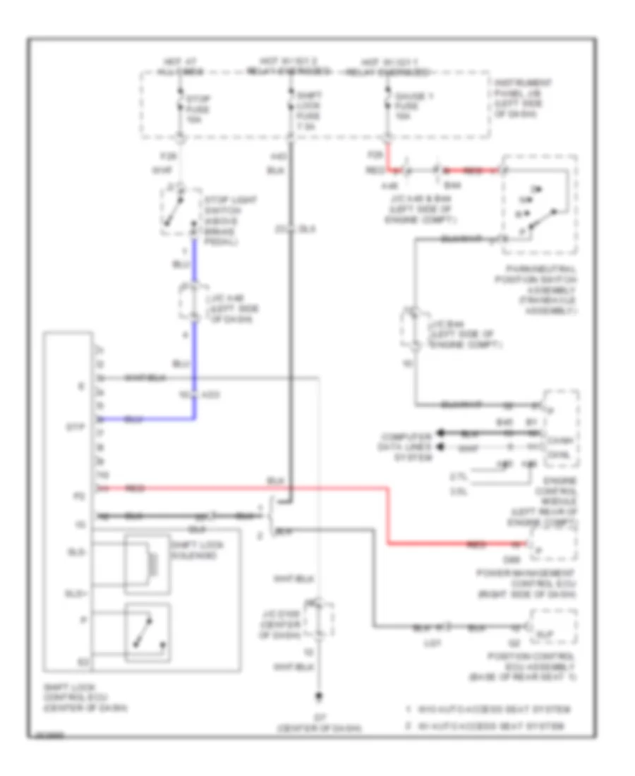
- Shift interlock system
- Slp
- Slr+
- Sp1
- Spd
- Ssw1
- Ssw2
- Sta
- Star
- Starting/ charging system
- Stop fuse 10a
- Stop light switch assembly (above brake pedal)
- Stp1
- Tion detec-
- W1 (rear tailgate)
- Wk2
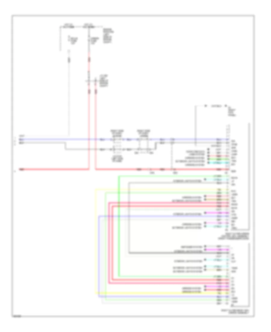
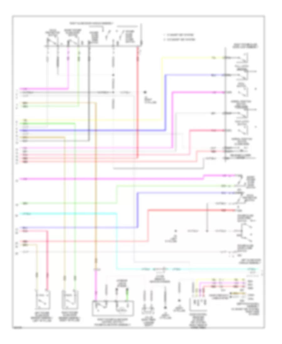
Forced Entry Wiring Diagram, with Smart Key System (2 of 4) for Toyota Sienna 2013
List of elements for Forced Entry Wiring Diagram, with Smart Key System (2 of 4) for Toyota Sienna 2013:
- (left side of dash) main body ecu
- A1 (left front of engine compt)
- A2 (left side of engine compt)
- Acc
- Act+
- Act-
- Actd
- Altb
- Bcty
- Bdsu
- Bzr
- C13
- C18
- Canh
- Canl
- D d/ul relay
- D/l fuse 15a
- D/l relay
- D/ul relay
- D1 (left kick panel)
- D13
- D14
- D2 (left side of engine compt)
- D21
- D23
- D32
- D35
- D94
- Data lines computer system
- Detec- tion
- Dim
- Dk1
- Drl
- Ecu- acc fuse 10a
- Ecu- ig 1 fuse 10a
- Engine room j/b (left side of engine compt)
- F13
- F20
- F21
- F22
- F23
- F24
- F25
- F33
- Flcy
- Frcy
- G1 (right kick panel)
- Gd1
- Gnd1
- Gnd2
- H1 (left "b" pillar)
- H26
- H27
- H35
- Haz
- Hcty
- Hd1
- Headlights system
- Hl4
- Hnsw
- Horn
- Horns system
- Hot at all times
- Hot in on or acc
- Hot in on or start
- Hrly
- Hrnh
- Ig1
- Ind
- Instrument panel j/b (left side of dash)
- Integration relay
- J/c a49
- J/c a51 (left side of engine compt)
- J/c d94 & l36 (right side of dash)
- J/c d95 (left side of dash)
- J/c d96 (left side of dash)
- J/c d99 (left side of dash)
- Jk2
- Jk3
- K2 (left "c" pillar)
- L36
- Left front door w/ motor lock assembly
- Left slide door full open stop lock assembly
- Lin2
- Lock key
- Lock un- key
- Lsfl
- Lsfr
- Lswl
- Lswr
- Obd fuse 7.5a
- Pnk
- Rcty
- Red
- Right front door w/ motor lock assembly
- Sbem
- Security horn assembly (left rear of engine compt)
- Sehn
- Shrn
- Tion detec-
- Turn signal flasher assembly (left side of dash)
- Ul3
- Wireless door lock buzzer (left front of engine compt)
Forced Entry Wiring Diagram, with Smart Key System (3 of 4) for Toyota Sienna 2013
List of elements for Forced Entry Wiring Diagram, with Smart Key System (3 of 4) for Toyota Sienna 2013:
- (left rear of engine compt) ecm
- (left side of dash) main body ecu
- 12v
- 2.7l
- 3.5l
- A2 (left side of engine compt)
- A39
- A55
- Ad4
- Agnd
- Back door lock assembly (power back courtesy door assembly)
- Bdsu
- Canh
- Canl
- Code
- Computer data lines system
- D12
- D13
- D36
- D7 (center of dash)
- Dk1
- Dk3
- Dl6
- Domr
- Door lock control switch
- Ecu-b 2 fuse 7.5a
- Ecu-b fuse 10a
- Engine hood courtesy switch (center front of engine compt)
- Engine room r/b (left side of engine compt)
- Engine switch
- F39
- G1 (right kick panel)
- Gd1
- Gnd
- H1 (left "b" pillar)
- Hd1
- Hot at all times
- Imi
- Imo
- Inds
- Indw
- Instrument panel j/b (left side of dash)
- Interior lights system
- J/c a49
- J/c d100 (left side of dash)
- J/c d102 (center of dash)
- J/c d94 (right side of dash)
- J/c d96 (left side of dash)
- J/c d98 (left side of dash)
- J/c w19 (power back door assembly)
- J/c w20 (power back door assembly)
- Kl1
- Lcty
- Left front door courtesy light switch (left "b" pillar)
- Left rear door courtesy light switch
- Lin1
- Lock
- Neo
- Pnk
- Power window regulator master switch assembly
- Red
- Right front door control switch
- Right front door courtesy light switch (right "b" pillar)
- Right rear door courtesy light switch (top of tailgate assembly)
- Ss1
- Ss2
- Swil
- Transponder key coil
- Txct
- Ul1
- Un- lock
- Vc5
- W/ power back door
- W/o power back door
- W1 (rear tailgate)
- Wk2
Forced Entry Wiring Diagram, with Smart Key System (4 of 4) for Toyota Sienna 2013
List of elements for Forced Entry Wiring Diagram, with Smart Key System (4 of 4) for Toyota Sienna 2013:
- (center console assembly) front indoor electrical key oscillator
- (left rear of luggage compt) indoor luggage compartment electrical key oscillator
- (rear bumper assembly) outside luggage electrical key antenna
- A33
- Ad3
- Ad4
- Agnd
- Ant1
- Ant2
- Canh
- Canl
- Certification ecu assembly (right side of dash)
- Cg1b
- Cg2b
- Cg5b
- Cg6b
- Cg7b
- Cg8b
- Clg1
- Clg2
- Clg3
- Clg4
- Clg5
- Clg6
- Clg7
- Clg8
- Clgb
- Code
- Computer data lines system
- Cutb
- D3 (right kick panel)
- D87
- D88
- Data
- Dl3
- Dl4
- Door control receiver (right rear of cargo area)
- Efii
- Efio
- Engine room r/b (left side of engine compt)
- G1 (right kick panel)
- Gd2
- Gnd
- H1 (left "b" pillar)
- Hd2
- Hot at all times
- Hot in on or start
- Ig2 fuse 7.5a
- Inds
- Instrument panel j/b (left side of dash)
- J/c d106 (right side of dash)
- L4 (right "d" pillar)
- Left front door outside handle assembly
- Lin
- Pnk
- Pos1
- Pos2
- Rco
- Rda
- Rear indoor electrical key oscillator
- Red
- Right front door outside handle assembly
- Rssi
- Sen1
- Sen2
- Sens
- Smart fuse 5a
- Swil
- Trg+
- Tsw1
- Tsw2
- Tsw5
- Tsw6
- Txct
- Vc5
- Og1
- Ph1
Forced Entry Wiring Diagram, without Smart Key System (1 of 2) for Toyota Sienna 2013
List of elements for Forced Entry Wiring Diagram, without Smart Key System (1 of 2) for Toyota Sienna 2013:
- (left front of engine compt) wireless door lock buzzer
- (power back door assembly) j/c w20
- (right "b" pillar) right front door courtesy light switch
- (right rear of cargo area)
- A2 (left side of engine compt)
- Acc
- Act+
- Act-
- Actd
- Altb
- Bcty
- Becu
- Bzr
- Canh
- Canl
- Computer data lines system
- D d/ul relay
- D/l fuse 15a
- D/l relay
- D/ul relay
- D1 (left kick panel)
- D12
- D13
- D14
- D2 (left side of engine compt)
- D23
- D32
- D35
- D36
- D7 (center of dash)
- D94
- Detec- tion
- Dim
- Dk1
- Dl6
- Domr
- Door control receiver
- Drl
- Ecu- acc fuse 10a
- Ecu- ig 1 fuse 10a
- F13
- F20
- F21
- F22
- F23
- F24
- F25
- F33
- F39
- Flcy
- Frcy
- G1 (right kick panel)
- Gd1
- Gnd
- Gnd1
- Gnd2
- H26
- H27
- H35
- Ha2
- Haz
- Hcty
- Headlights system
- Horn
- Hot at all times
- Hot in on or acc
- Hot in on or start
- Hrly
- Il2
- Il3
- Ind
- Instrument panel j/b (left side of dash)
- Interior lights system
- J/c 105 (center of dash)
- J/c a49
- J/c d100 (left side of dash)
- J/c d94 & l36 (right side of dash)
- J/c d94 & l36 (right side of dash) d94
- J/c d95 (left side of dash)
- J/c d96 (left side of dash)
- J/c d98 (left side of dash)
- J/c d99 (left side of dash)
- Jk2
- Jk3
- K2 (left "c" pillar)
- Kl1
- Ksw
- L2 (right "c" pillar)
- L36
- L4 (right "d" pillar)
- Lcty
- Left slide door full open stop lock assembly
- Lin2
- Lock
- Lock un-
- Lsfl
- Lsfr
- Lswl
- Lswr
- Main body ecu (left side of dash)
- Obd fuse 7.5a
- Pnk
- Prg
- Rcty
- Rda
- Red
- Right front door control switch
- Right front door w/ motor lock assembly
- Right side door full open stop lock assembly
- Sbem
- Tion detec-
- Turn signal flasher assembly (left side of dash)
- Ul1
- Ul3
- Un-lock warning switch assembly
- W/ power back door
- W/o power back door
- Wk2
Forced Entry Wiring Diagram, without Smart Key System (2 of 2) for Toyota Sienna 2013
List of elements for Forced Entry Wiring Diagram, without Smart Key System (2 of 2) for Toyota Sienna 2013:
- (left "b" pillar) left front door courtesy light switch
- (left side of engine compt) j/c a51
- (power back door assembly)
- (top of tailgate assembly) right rear door courtesy light switch
- +b (dome)
- 12v
- A1 (left front of engine compt)
- A2 (left side of engine compt)
- A55
- Ad4
- Back door lock assembly
- Buzzer
- C13
- C18
- Canh
- Canl
- Combination meter assembly
- Computer data lines system
- Courtesy
- D6 (center of dash)
- Detec- tion
- Dk3
- Dl6
- Door ind
- Door lock control switch
- Drive ic
- Ecu-b 2 fuse 7.5a
- Ecu-b fuse 10a
- Engine hood courtesy switch (center front of engine compt)
- Engine room j/b (left side of engine compt)
- Engine room r/b (left side of engine compt)
- Gauge 2 fuse 7.5a
- Gnd2
- H1 (left "b" pillar)
- Hd1
- Headlights system
- Hl4
- Hnsw
- Horns system
- Hot at all times
- Hot in on or start
- Hrnh
- Ig+
- Ig1
- Instrument panel j/b (left side of dash)
- Integration relay
- J/c a49
- J/c d100 (left side of dash)
- J/c d96 (left side of dash)
- J/c d98 (left side of dash)
- J/c w19 (power back door assembly)
- Left front door w/ motor lock assembly
- Left rear door courtesy light switch
- Lin1
- Lock
- Lock key
- Mgnd
- Micro processor
- Pnk
- Power window regulator master switch assembly
- Red
- Security horn assembly (left rear of engine compt)
- Security ind
- Sehn
- Shrn
- Un- key
- W/ power back door
- W/o power back door
- W1 (rear tailgate)
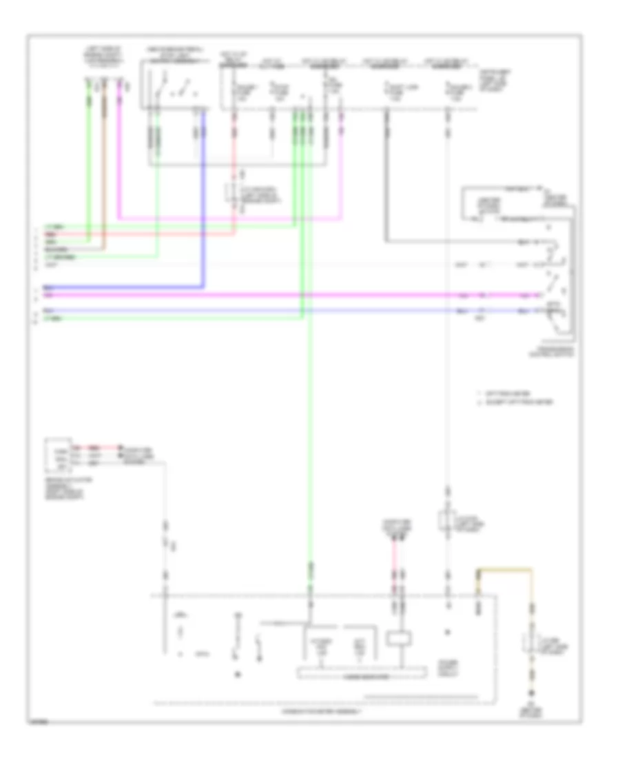
Immobilizer Wiring Diagram, with Smart Key System for Toyota Sienna 2013
List of elements for Immobilizer Wiring Diagram, with Smart Key System for Toyota Sienna 2013:
- (left side of dash) j/c d96
- +b dome
- A39
- A55
- Ad3
- Agnd
- Canh
- Canl
- Certification ecu (right side of dash)
- Code
- Combination meter assembly
- Computer data lines system
- Cutb
- D21
- D3 (right kick panel)
- D35
- D36
- D6 (center of dash)
- D88
- Ecm (left rear of engine compt)
- Ecu-b fuse 10a
- Efii
- Efio
- Engine room r/b (left side of engine compt)
- Engine switch
- F39
- Gauge 2 fuse 7.5a
- Hot at all times
- Hot in on or start
- Ig+
- Imi
- Imo
- Ind
- Inds
- Instrument panel j/b (left side of dash)
- J/c d100 (center of dash)
- J/c d100 (left side of dash)
- J/c d106 (right side of dash)
- J/c d94 (right side of dash)
- J/c d98 (left side of dash)
- Key coil transponder
- Main body ecu
- Mgnd
- Micro computer
- Pnk
- Red
- Security ind
- Txct
- Vc5
Immobilizer Wiring Diagram, without Smart Key System for Toyota Sienna 2013
List of elements for Immobilizer Wiring Diagram, without Smart Key System for Toyota Sienna 2013:
- +b dome
- 2.7l
- 3.5l
- A33
- A39
- A55
- Ad3
- Ad4
- Agnd
- Ant1
- Ant2
- Code
- Combination meter assembly
- Cty
- D18
- D2 (left side of engine compt)
- D21
- D35
- D36
- D6 (center of dash)
- D7 (center of dash)
- Dd1
- Dlc3 (left side of dash)
- Dome fuse 7.5a
- Ecm (left rear of engine compt)
- Ecu-b fuse 10a
- Efii
- Efio
- Engine room r/b (left side of engine compt)
- F39
- Gnd
- H35
- Hot at all times
- Hot in on or start
- Ig2 fuse 7.5a
- Ignition key cylinder light ind
- Im1
- Imo
- Ind
- Instrument panel j/b (left side of dash)
- Interior lights system
- J/c a52 (left side of engine compt)
- J/c d100 (left side of dash)
- J/c d105 (center of dash)
- J/c d107 (right side of dash)
- J/c d96 (left side of dash)
- J/c d98 (left side of dash)
- J/c d99 (left side of dash)
- Key coil transponder
- Ksw
- Left front door courtesy light switch (left "b" pillar)
- Mgnd
- Micro computer
- Pnk
- Red
- Security ind
- Sil
- Transponder key amplifier (left side of dash)
- Transponder key ecu assembly (center of dash)
- Txct
- Un-lock warning switch assembly
- Vc5
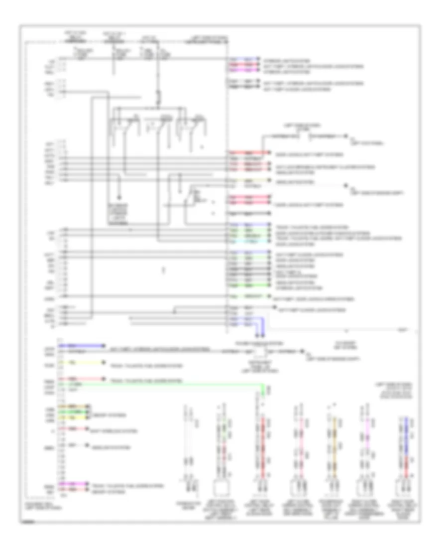
BODY CONTROL MODULES
Body ECU Wiring Diagram (1 of 2) for Toyota Sienna 2013
List of elements for Body ECU Wiring Diagram (1 of 2) for Toyota Sienna 2013:
- (left side of dash) instrument panel j/b
- (left side of dash) j/c d117, d118, d119, d120, d121, d122, d123 & d124
- (left side of dash) j/c d99
- Acc
- Act+
- Act-
- Actd
- Altb
- Anti theft & door locks systems
- Anti theft, interior lights & door locks systems
- Anti-lock brakes & instrument cluster systems
- Anti-theft & door locks systems
- Anti-theft, door locks & horns systems
- Becu
- Bk d/l relay
- Bzr
- Canh
- Canl
- Cann
- Canp
- Combination meter
- D d/ul relay
- D/l fuse 15a
- D/l relay
- D/ul relay
- D1 (left kick panel)
- D11
- D117
- D118
- D119
- D120
- D121
- D122
- D123
- D124
- D14
- D2 (left side of engine compt)
- D21
- D23
- D27
- D28
- D29
- D32
- D35
- D36
- Dim
- Dk2
- Dl1
- Door locks & anti-theft systems
- Door locks system
- Door locks system & power windows systems
- Drl
- Ecu-acc fuse 10a
- Ecu-ig 1 fuse 10a
- Exterior lights & interior
- F13
- F16
- F20
- F21
- F22
- F23
- F24
- F25
- F39
- F40
- Ffgo
- Flcy
- Frcl
- Frcy
- Fspt
- Gd2
- Gnd1
- Gnd2
- H12
- H23
- H26
- H27
- H35
- Hcty
- Hd2
- Headlights system
- Horn
- Hot at all times
- Hot w/ acc relay energized
- Hot w/ ig1 1 relay energized
- Hrly
- Il2
- Ile
- Ind
- Instrument panel j/b (left side of dash)
- Interior lights system
- Jk2
- Ky1
- Left door control relay (left rear sliding door)
- Left outer mirror control ecu assembly (driver's door)
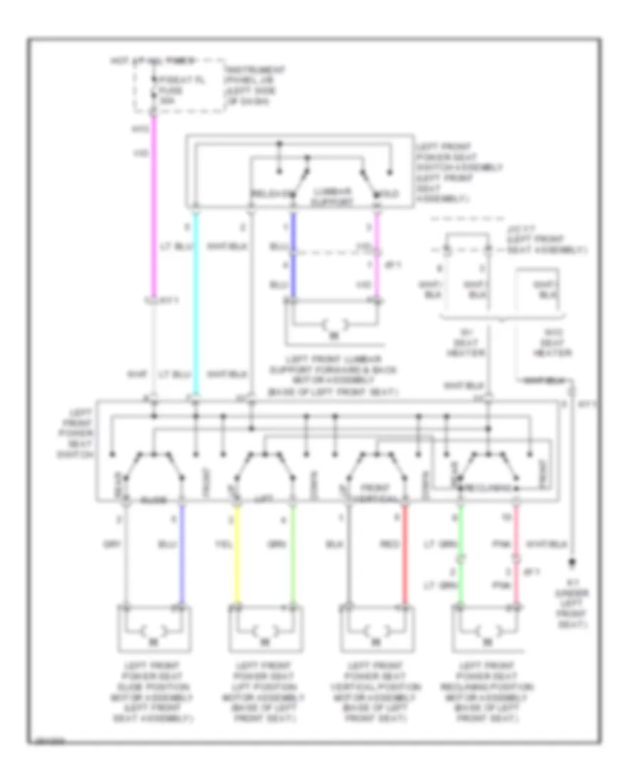
- Left position control ecu & switch assembly (left front seat assembly)
- Lights
- Lin2
- Lswl
- Lswr
- Main body ecu (left side of dash)
- Memory systems
- Mirb
- Mire
- Mirs
- Mpx1
- Mpx2
- Msch
- Mscl
- Obd fuse 7.5a
- Pbds
- Pkb
- Pnk
- Power back door unit assembly (left "d" pillar)
- Power windows system
- Red
- Ret
- Right door control relay (right rear sliding door)
- Right outer mirror control ecu assembly (front passenger's door)
- Rlsd
- Rrsd
- Sbem
- Shift interlock system
- Systems
- Tr+
- Trly
- Trunk, tailgate, fuel doors system
- Trunk, tailgate, fuel doors, anti-theft & door locks systems
- W/o smart key system
Body ECU Wiring Diagram (2 of 2) for Toyota Sienna 2013
List of elements for Body ECU Wiring Diagram (2 of 2) for Toyota Sienna 2013:
- (left side of dash)
- 2.7l
- 3.5l
- A/c amplifier assembly (right side of dash)
- A39
- A55
- Ad3
- Air bag sensor assembly (center of dash)
- Air conditioning & headlights systems
- Anti theft, door locks & interior lights systems
- Anti theft, interior lights, trunk, tailgate, fuel doors & door locks systems
- Anti-theft & door locks systems
- Anti-theft, door locks & interior lights systems
- Anti-theft, door locks systems
- Anti-theft, interior lights & door locks systems
- Awd ecu assembly (left side of dash)
- Bcty
- Bdsu
- Brake actuator assembly (right side of engine compt)
- Ca1h
- Ca1l
- Canh
- Canl
- Certification ecu (w/ smart key system) (right side of dash)
- Cltb
- Clte
- Clts
- Combination meter
- Cspt
- D12
- D13
- D35
- D40
- D75
- D88
- D89
- Da4
- Data link connector 3 (left side of dash)
- Dk2
- Dl1
- Domr
- Ecm (left rear of engine compt)
- Ecu-b fuse 10a
- Engine room r/b (left side of engine compt)
- Exterior lights system
- Exterior lights, headlights & interior lights systems
- Ffog
- Flcl
- Haz
- Head
- Headlights system
- Hot at all times
- Interior lights system
- J/c d125
- J/c d126
- Ksw
- Lcty
- Lsfl
- Lsfr
- Main body ecu (left side of dash)
- Network gateway ecu (right side of dash)
- Pnk
- Power management control ecu (right side of dash)
- Power steering ecu assembly (left side of dash)
- Power tops & power windows systems
- Prg
- Pws
- Rcty
- Rda
- Red
- Steering sensor (inside steering column)
- Tail
- Trunk, tailgate, fuel doors & door locks systems
- Ul1
- Ul3
- W/ smart key system
- W/ vehicle dynamics integrated management
- W/o smart key system
- Warning & interior lights systems
- Yaw rate sensor (w/ vehicle dynamics integrated management) (center console)
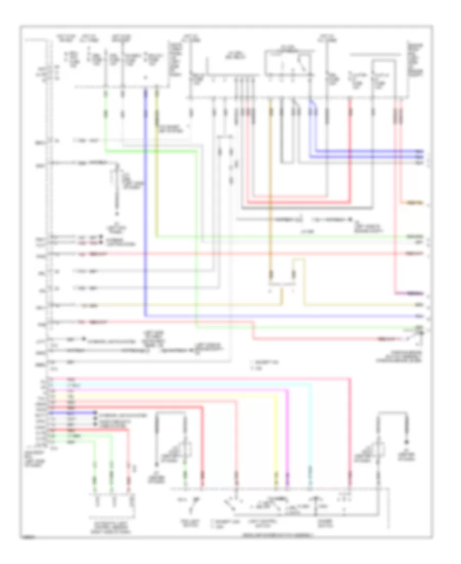
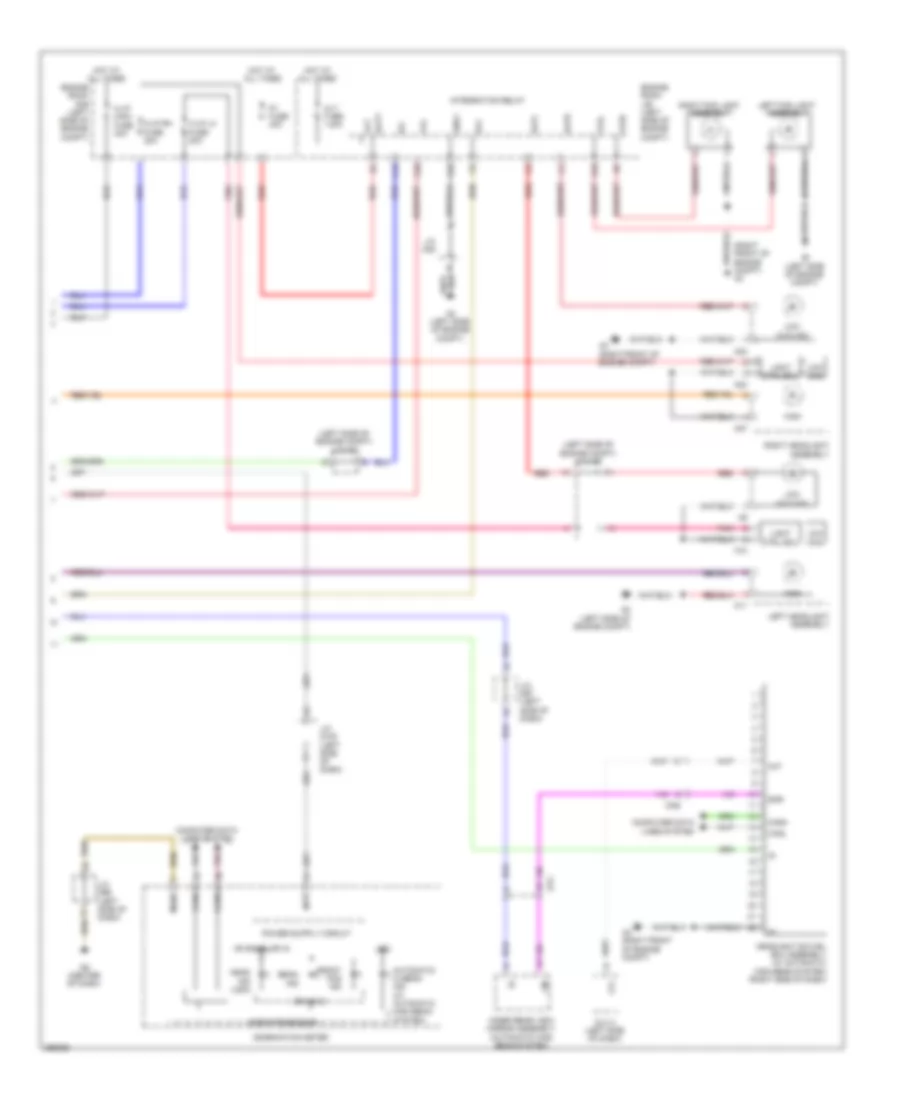
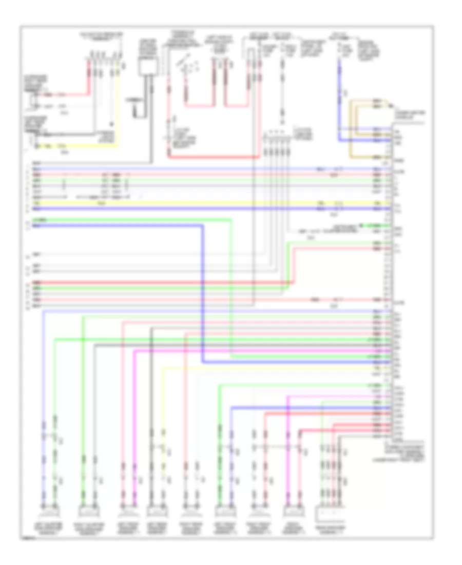
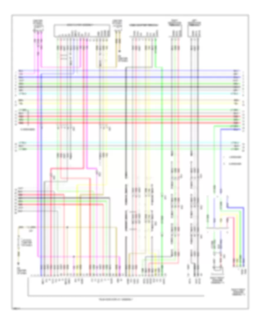
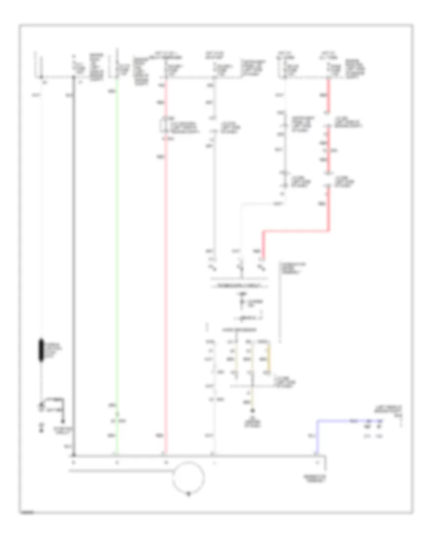
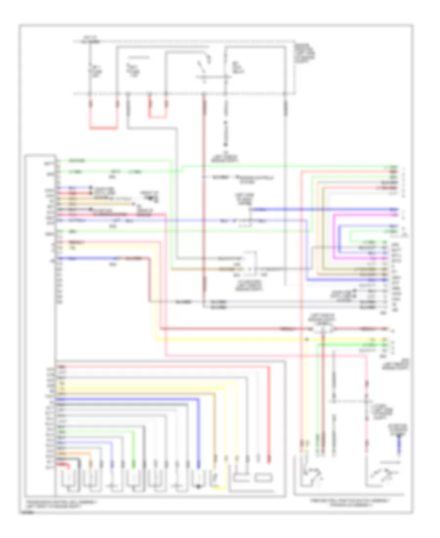
Integration Control and Panel Wiring Diagram for Toyota Sienna 2013
List of elements for Integration Control and Panel Wiring Diagram for Toyota Sienna 2013:
- (left side of engine compt) engine room j/b
- A1 (left front of engine compt)
- A2 (left side of engine compt)
- Alt
- Alt fuse 140a
- Anti theft & door locks systems
- Batt
- C13
- C14
- C16
- C18
- C22
- C26
- D10
- Decr
- Def
- Defogger system
- Ecu-ig 1 fuse 10a
- Engine room r/b (left side of engine compt)
- Exterior lights & interior lights systems
- F21
- F33
- Ffg
- Ffgl
- Ffgr
- Gnd1
- Gnd2
- H-lp relay
- Headlights system
- Hl4
- Hlpl
- Hlpr
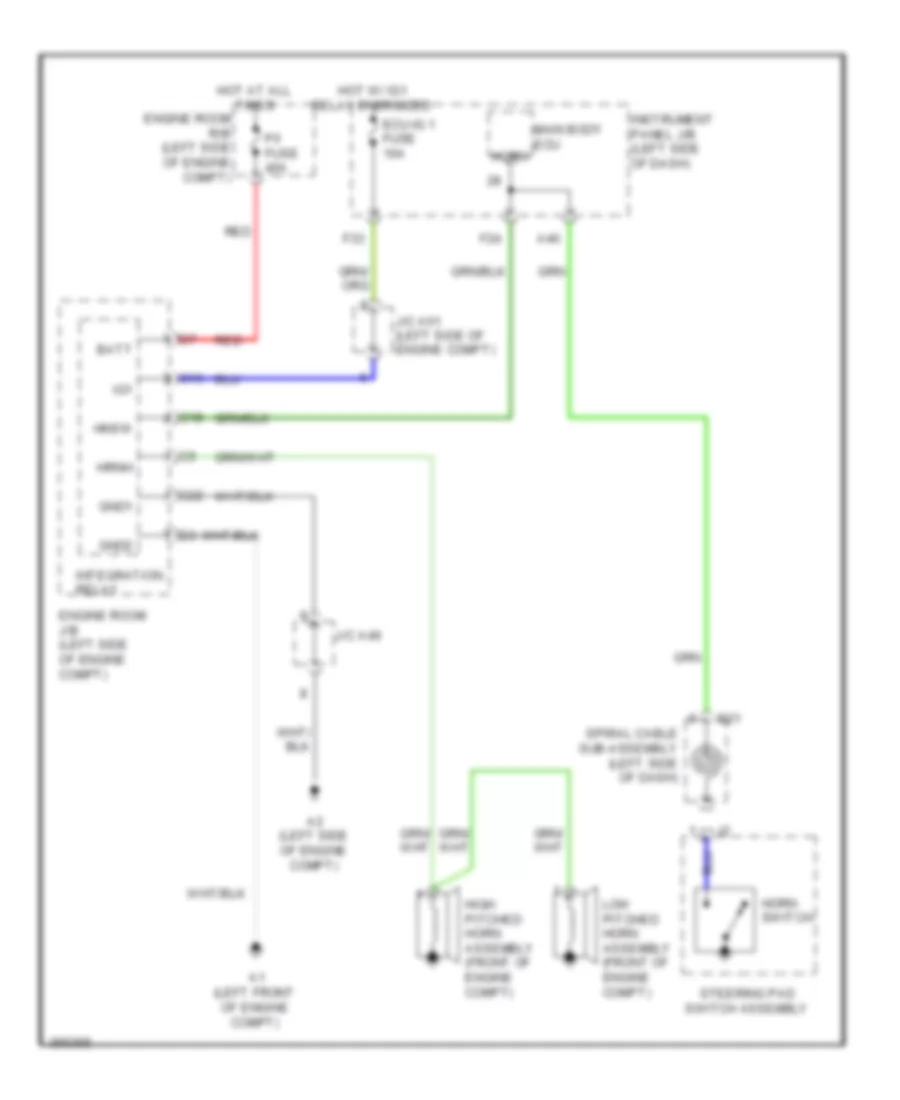
- Hnsw
- Horns system
- Horns, door locks & anti-theft systems
- Hot at all times
- Hot w/ ig1 1 relay energized
- Hrnh
- Ig1
- Instrument panel j/b (left side of dash)
- Integration relay
- J/c a49
- J/c a51 (left side of engine compt)
- Main body ecu hrly
- Mhtr
- P/i fuse 40a
- Pnk
- Rdef
- Red
- Sehn
- Shrn
- Tail
- W/ hid
- W/o hid
- Wiper/washer & defogger systems
COMPUTER DATA LINES
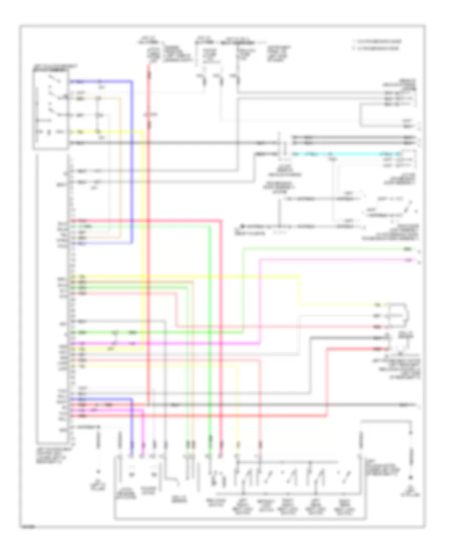
Computer Data Lines Wiring Diagram (1 of 2) for Toyota Sienna 2013
List of elements for Computer Data Lines Wiring Diagram (1 of 2) for Toyota Sienna 2013:
- (center of dash) d7
- (center of dash) j/c d114, d115, d116, d110, d111, d112 & d113
- (left rear of engine compt) (w/ smart key system) ecm
- (left side of dash) j/c d127
- (right side of dash) (w/ smart key system) power management control ecu
- (right side of dash) headlight swivel ecu assembly
- 2.7l
- 3.5l
- A/c amplifier assembly (right side of dash)
- A35
- A39
- A55
- A56
- Brake actuator assembly (right side of engine compt)
- Ca1h
- Ca1l
- Ca2h
- Ca2l
- Ca3n
- Ca3p
- Canh
- Canl
- Cann
- Canp
- Certification ecu assembly (right side of dash)
- Clearance warning ecu assembly (right side of dash)
- Combination meter assembly
- D110
- D111
- D112
- D113
- D114
- D115
- D116
- D3 (right kick panel)
- D38
- D75
- D83
- D86
- D88
- D89
- Da4
- Da6
- Driving support ecu assembly (right side of dash)
- Ecu-ig 1 fuse 10a
- Ecu-ig 2 fuse 10a
- Gnd
- Hot at all times
- Hot w/ ig1 1 relay energized
- Hot w/ ig1 2 relay energized
- Ig1
- Ig2
- Instrument panel j/b (left side of dash)
- Int
- J/c d105 (center of dash)
- J/c d106 (right side of dash)
- J/c d125
- J/c d97 (left side of dash)
- J/c d99 (left side of dash)
- Msch
- Mscl
- Network gateway ecu (w/o smart key system) (right side of dash)
- Obd fuse 7.5a
- Parking assist ecu (right side of dash)
- Pnk
- Red
- Seat belt control ecu (right side of dash)
- St plug
- Tach
- W/ smart key system
- W/o smart key system
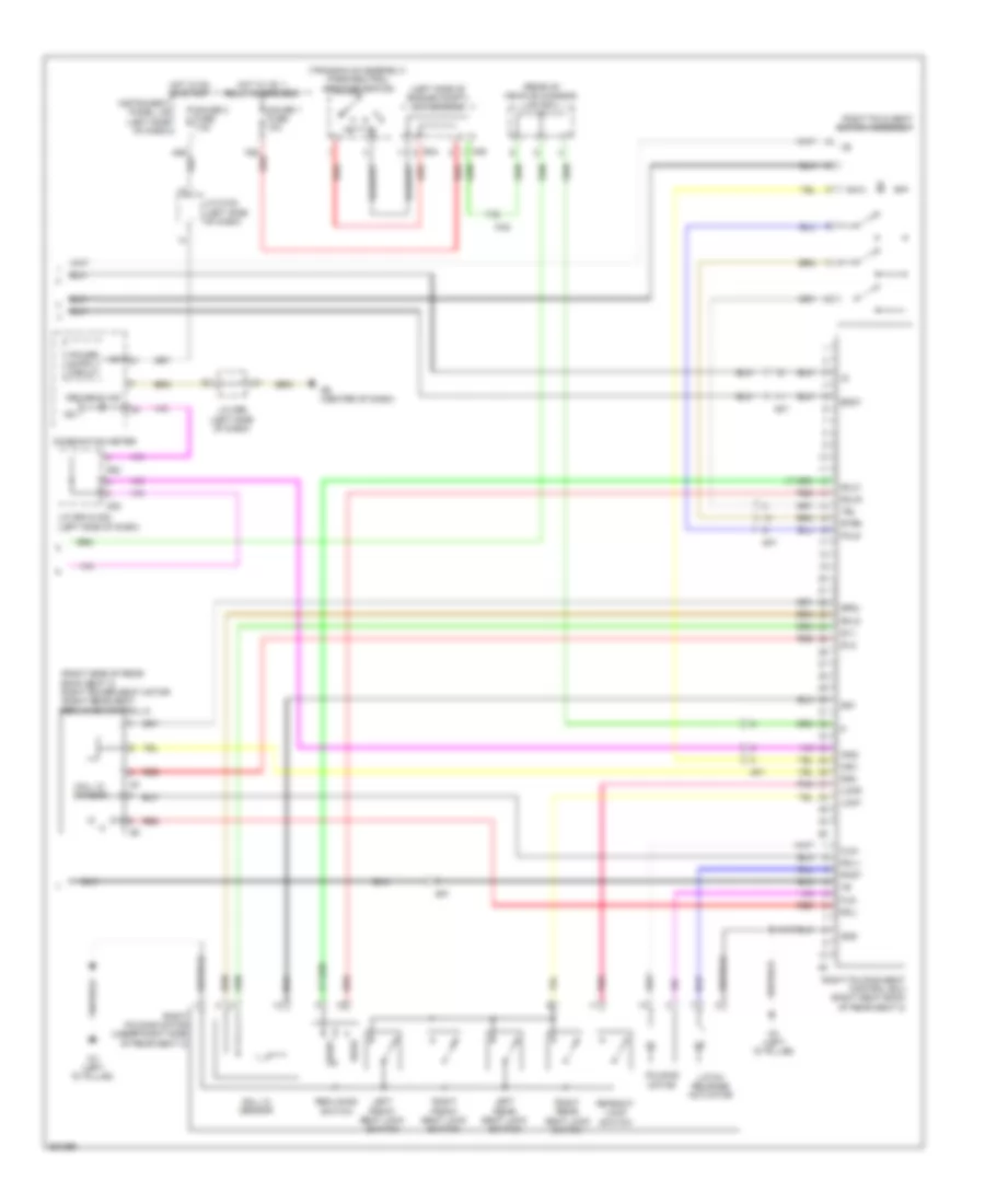
Computer Data Lines Wiring Diagram (2 of 2) for Toyota Sienna 2013
List of elements for Computer Data Lines Wiring Diagram (2 of 2) for Toyota Sienna 2013:
- (center console) yaw rate sensor
- (inside steering column) steering sensor
- (left side of dash) j/c d117, d118, d119, d120, d121, d122, d123 & d124
- (left side of dash) j/c d126
- (left side of dash) main body ecu
- (left side of dash) tire pressure warning ecu
- (right side of dash) dcm (telematics transceiver)
- (right side of dash) power steering ecu assembly
- Ad3
- Ad4
- Air bag sensor assembly (center of dash)
- Awd ecu assembly (left side of dash)
- B1 (3.5l) (rear of engine)
- B4 (2.7l) (rear of engine)
- Ba1
- Batt
- Canh
- Canl
- Cann
- Canp
- D117
- D118
- D119
- D120
- D121
- D122
- D123
- D124
- D13
- D14
- D2 (left side of engine compt)
- D35
- D40
- Da6
- Dk2
- Dl1
- Dl3
- Dlc3 (left side of dash)
- Gd2
- Hd2
- Il2
- J/c d107 (right side of dash)
- J/c d96 (left side of dash)
- Jk2
- Ky1
- Left door control relay (left rear sliding door)
- Left outer mirror control ecu assembly (driver's door)
- Left position control ecu & switch assembly (left front seat assembly)
- Lvl
- Lx1
- Mpx1
- Mpx2
- Occupant detection ecu (base of right front seat)
- Pnk
- Power back door unit assembly (left "d" pillar)
- Red
- Right door control relay (right rear sliding door)
- Right outer mirror control ecu assembly (front passenger's door)
- Sil
- Tac
- W/ smart key system
- W/o smart key system
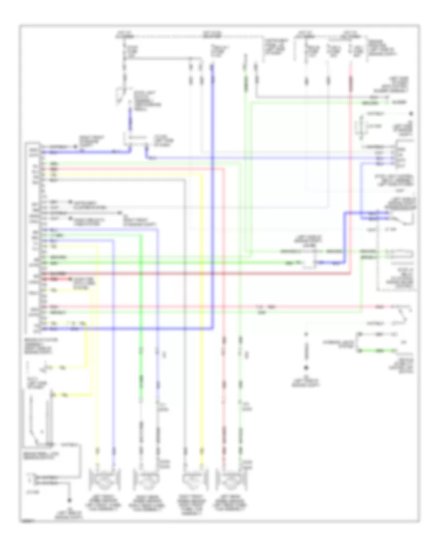
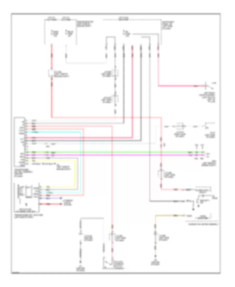
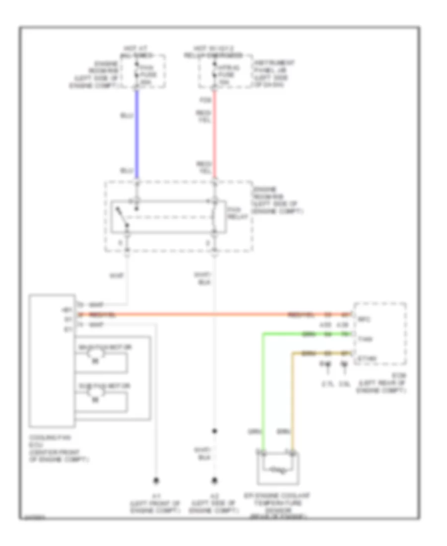
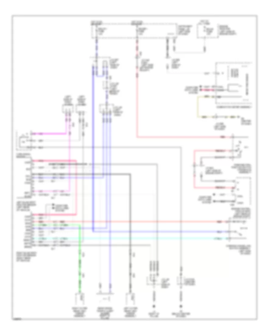
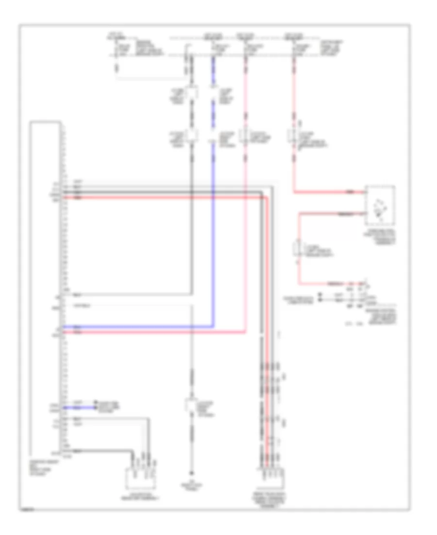
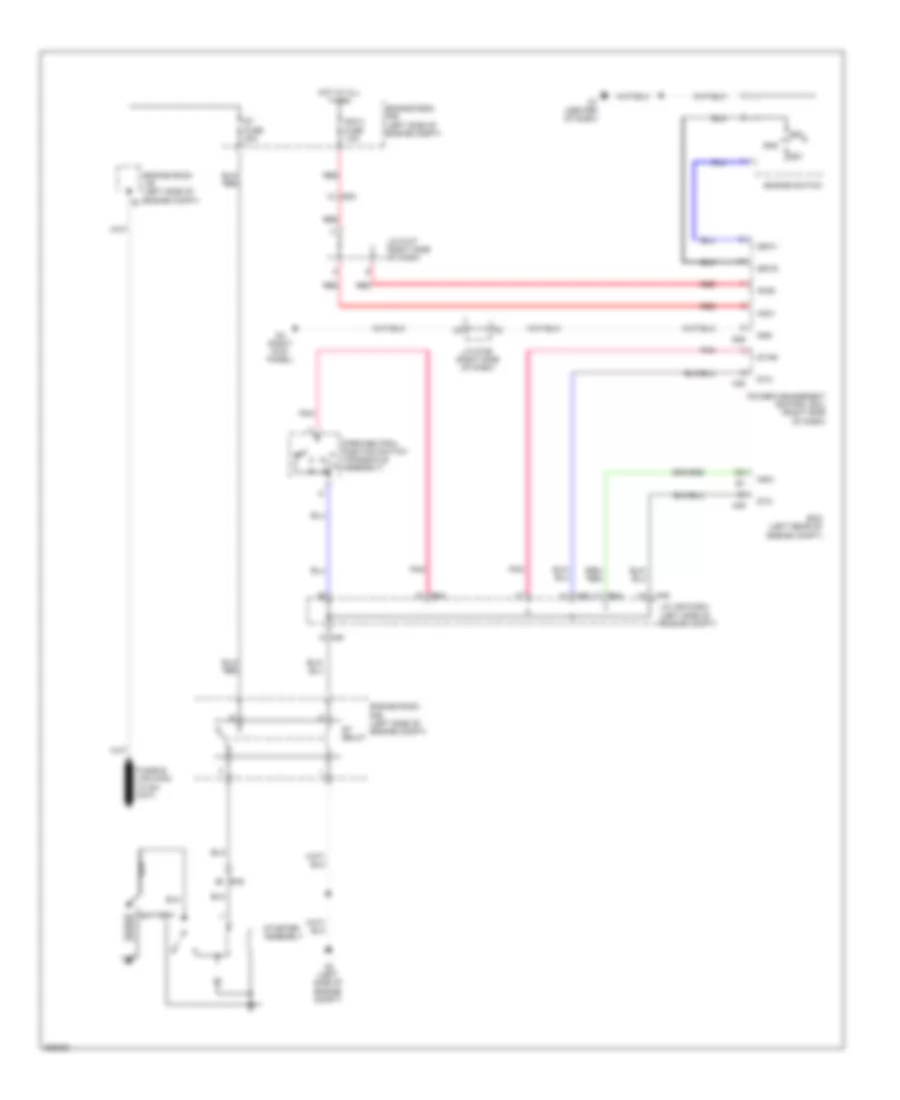
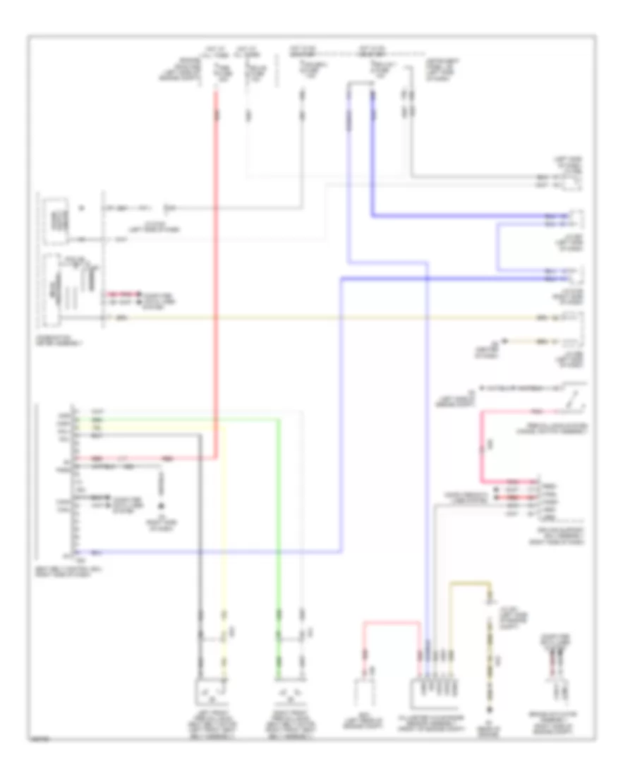
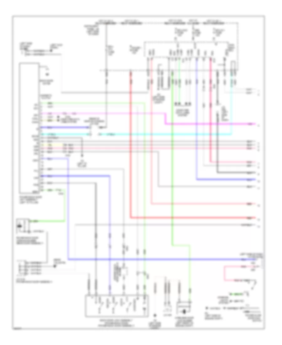
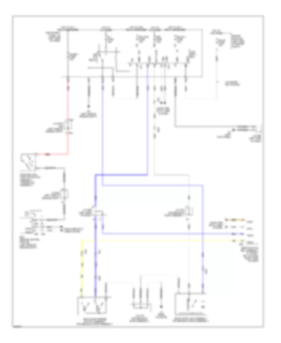
COOLING FAN
Cooling Fan Wiring Diagram for Toyota Sienna 2013
List of elements for Cooling Fan Wiring Diagram for Toyota Sienna 2013:
- +b1
- 2.7l
- 3.5l
- A1 (left front of engine compt)
- A2 (left side of engine compt)
- A39
- A55
- B45
- Cooling fan ecu (center front of engine compt)
- Ecm (left rear of engine compt)
- Efi engine coolant temperature sensor (rear of engine)
- Engine room r/b (left side of engine compt)
- Ethw
- F28
- Fan fuse 60a
- Fan relay
- Hot at all times
- Hot w/ ig1 2 relay energized
- Htr-ig fuse 10a
- Instrument panel j/b (left side of dash)
- Main fan motor
- Rfc
- Sub fan motor
- Thw
CRUISE CONTROL
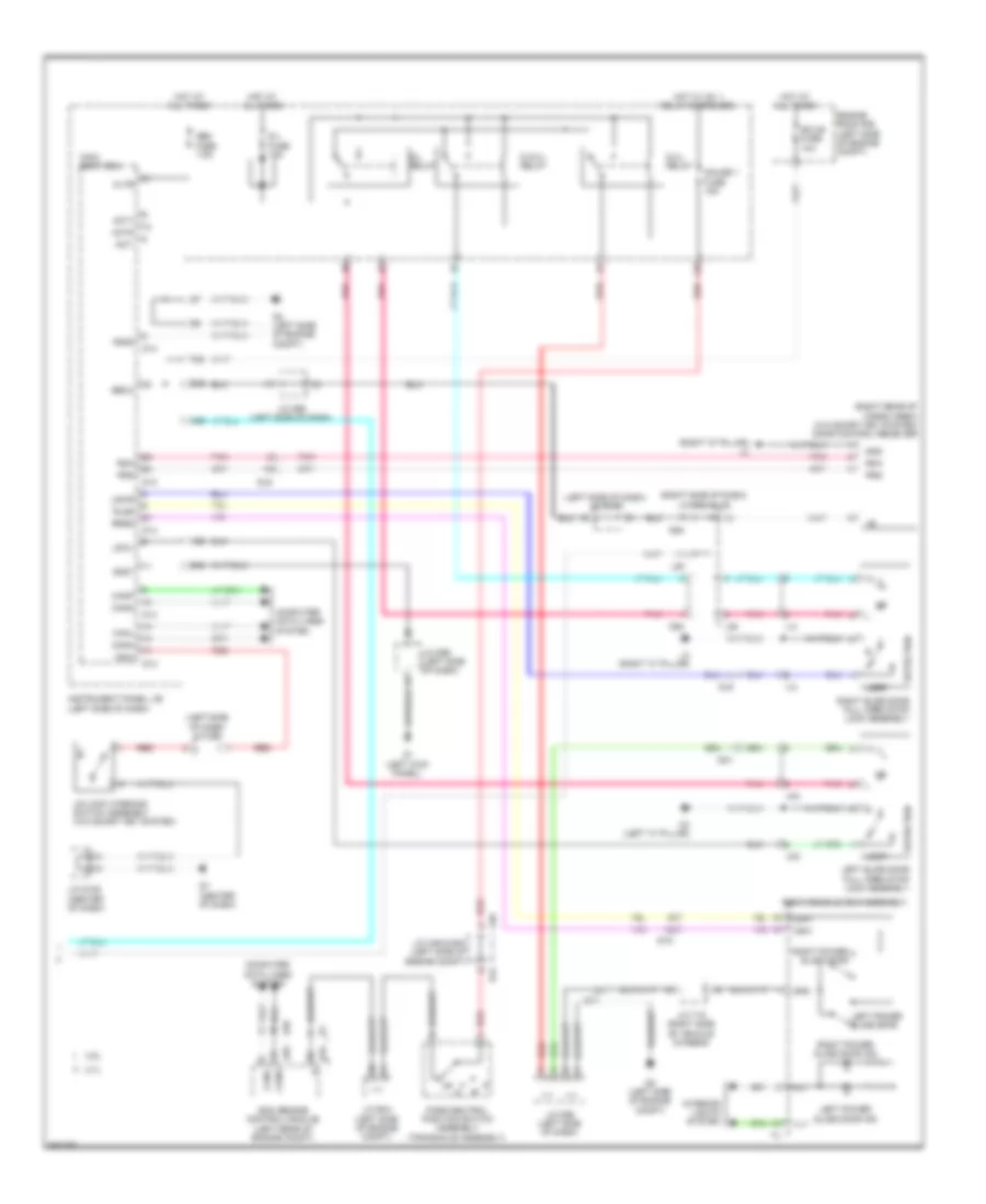
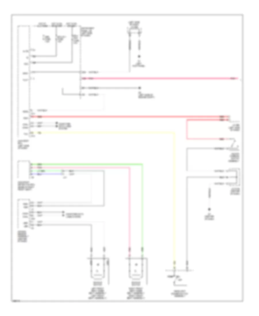
2.7L
2.7L, Cruise Control Wiring Diagram (1 of 2) for Toyota Sienna 2013
List of elements for 2.7L, Cruise Control Wiring Diagram (1 of 2) for Toyota Sienna 2013:
- +b2
- +res
- -set
- A2 (left side of engine compt)
- A55
- Accelerator position sensor (accelerator pedal assembly)
- Ad4
- B4 (rear of engine)
- B45
- Ba2
- Can h
- Can l
- Cancel
- Ccs
- Computer data lines system
- Cruise control main switch
- Cruise control switch
- D21
- Dome fuse 7.5a
- Ecm (left rear of engine compt)
- Ecu-b fuse 10a
- Efi 1 fuse 25a
- Efi main relay
- Engine controls system
- Engine room r/b (left side of engine compt)
- Epa
- Epa2
- Eta
- Ge01
- Hot at all times
- J/c a51 (left side of engine compt)
- J/c a52 (left side of engine compt)
- Mrel
- On/off
- Pnk
- Red
- Spd
- Spiral cable sub-assembly (left side of dash)
- St-
- Stp
- Throttle w/ motor body assembly (intake manifold assembly)
- Vcp2
- Vcpa
- Vcta
- Vpa
- Vpa2
- Vta
- Vta1
- Vta2
2.7L, Cruise Control Wiring Diagram (2 of 2) for Toyota Sienna 2013
List of elements for 2.7L, Cruise Control Wiring Diagram (2 of 2) for Toyota Sienna 2013:
- (left side of dash) j/c d100
- A/t/odo/acc lcd
- A/t/odo/lcd
- A30
- A46
- A55
- Ad4
- B44
- Ba2
- Brake actuator assembly (right side of engine compt)
- Can i/f
- Canh
- Canl
- Circuit
- Combination meter assembly
- Computer data lines system
- Cruise ind
- D36
- D6 (center of dash)
- D98
- D99
- Da4
- Drive ic
- Except optitron meter
- F19
- F26
- F29
- F34
- F35
- F39
- Fl+
- Fl-
- Fr+
- Fr-
- Gauge 1 fuse 10a
- Gauge 2 fuse 7.5a
- Hot at all times
- Hot in on or start
- Hot w/ ig1 1 relay energized
- Ig2
- Ig2 fuse 7.5a
- Instrument panel j/b (left side of dash)
- J/c a46 & b44 (left side of engine compt)
- J/c a48 (left side of dash)
- J/c d96 (left side of dash)
- J/c d99 & d98 (left side of dash)
- Ka2
- La1
- Left front speed sensor (left front wheel hub assembly)
- Left rear speed sensor (left rear wheel hub assembly)
- Micro computer
- Optitron meter
- Park/neutral position switch assembly (transaxle assembly)
- Pnk
- Red
- Right front speed sensor (right front wheel hub assembly)
- Right rear speed sensor (right rear wheel hub assembly)
- Rl+
- Rl-
- Rr+
- Rr-
- Set ind
- Sp1
- Spd
- Stop fuse 10a
- Stop light switch assembly (above brake pedal)
- Stp
- Transmission control ecu assembly (left front of engine compt)
- Kl1 (2wd)
- Nk1
3.5L
3.5L, Cruise Control Wiring Diagram (1 of 2) for Toyota Sienna 2013
List of elements for 3.5L, Cruise Control Wiring Diagram (1 of 2) for Toyota Sienna 2013:
- +b2
- +res
- -set
- A2 (left side of engine compt)
- A39
- Accelerator position sensor (accelerator pedal assembly)
- Ad4
- B1 (rear of engine)
- B3 (top of engine)
- Ba2
- Can h
- Can l
- Cancel
- Ccs
- Computer data lines system
- Cruise control main switch
- Cruise control switch
- D21
- Dome fuse 7.5a
- E01
- Ecm (left rear of engine compt)
- Ecu-b fuse 10a
- Efi 1 fuse 25a
- Efi main relay
- Engine controls system
- Engine room r/b (left side of engine compt)
- Epa
- Epa2
- Eta
- Ge01
- Hot at all times
- J/c a51 (left side of engine compt)
- J/c a52 (left side of engine compt)
- Mrel
- On/off
- Pnk
- Red
- Spd
- Spiral cable sub-assembly (left side of dash)
- St-
- Stp
- Throttle w/ motor body assembly (intake manifold assembly)
- Vcp2
- Vcpa
- Vcta
- Vpa
- Vpa2
- Vta
- Vta1
- Vta2
3.5L, Cruise Control Wiring Diagram (2 of 2) for Toyota Sienna 2013
List of elements for 3.5L, Cruise Control Wiring Diagram (2 of 2) for Toyota Sienna 2013:
- (2wd)
- (awd)
- (left side of dash) j/c d100
- A/t/odo/acc lcd
- A/t/odo/lcd
- A30
- A46
- A55
- Ad4
- B44
- Ba2
- Brake actuator assembly (right side of engine compt)
- Can i/f
- Canh
- Canl
- Circuit
- Combination meter assembly
- Computer data lines system
- Cruise ind
- D36
- D6 (center of dash)
- D98
- D99
- Da4
- Drive ic
- Except optitron meter
- F19
- F26
- F29
- F34
- F35
- F39
- Fl+
- Fl-
- Fr+
- Fr-
- Gauge 1 fuse 10a
- Gauge 2 fuse 7.5a
- Hot at all times
- Hot in on or start
- Hot w/ ig1 1 relay energized
- Ig2
- Ig2 fuse 7.5a
- Instrument panel j/b (left side of dash)
- J/c a46 & b44
- J/c a48 (left side of dash)
- J/c d96 (left side of dash)
- J/c d99 (left side of dash)
- Ka2
- La1
- Left front speed sensor (left front wheel hub assembly)
- Left rear speed sensor (left rear wheel hub assembly)
- Micro computer
- Optitron meter
- Park/neutral position switch assembly (transaxle assembly)
- Pnk
- Red
- Right front speed sensor (right front wheel hub assembly)
- Right rear speed sensor (right rear wheel hub assembly)
- Rl+
- Rl-
- Rr+
- Rr-
- Set ind
- Sp1
- Spd
- Stop fuse 10a
- Stop light switch assembly (above brake pedal)
- Stp
- Transmission control ecu assembly (left front of engine compt)
- Kl1 (2wd)
- Nk1
3.5L, Dynamic Laser Cruise Control Wiring Diagram (1 of 3) for Toyota Sienna 2013
List of elements for 3.5L, Dynamic Laser Cruise Control Wiring Diagram (1 of 3) for Toyota Sienna 2013:
- (left side of dash) stop light control relay assembly
- +b2
- A2 (left side of engine compt)
- A39
- A46
- Accelerator position sensor (accelerator pedal assembly)
- B1 (rear of engine)
- B44
- Ba2
- Batt
- Can+
- Can-
- Cchg
- Ccs
- Computer data lines system
- Ecm (left rear of engine compt)
- Ect fuse 7.5a
- Ecu-b fuse 10a
- Efi 1 fuse 25a
- Efi main relay
- Engine controls system
- Engine room r/b (left side of engine compt)
- Epa
- Epa2
- Eta
- Ge01
- Gnd
- Hot at all times
- Igsw
- J/c a46 & b44 (left side of engine compt)
- J/c a46 (left side of engine compt)
- J/c a49
- Lgnd
- Mrel
- Out
- Park/neutral position switch assembly (transaxle assembly)
- Pnk
- Red
- St-
- Stop lp relay
- Stp
- Throttle w/ motor body assembly (intake manifold assembly)
- Transmission control ecu assembly (left front of engine compt)
- Vcp2
- Vcpa
- Vcta
- Vpa
- Vpa2
- Vta1
- Vta2
3.5L, Dynamic Laser Cruise Control Wiring Diagram (2 of 3) for Toyota Sienna 2013
List of elements for 3.5L, Dynamic Laser Cruise Control Wiring Diagram (2 of 3) for Toyota Sienna 2013:
- (above brake pedal) stop light switch assembly
- (left side of engine compt) j/c a51
- +res
- -set
- A10
- A55
- Ad4
- B1 (rear of engine)
- Ba2
- Buzzer
- Cancel
- Combination meter
- Computer data lines system
- Cruise control main switch
- Cruise control switch
- Cruise ind
- Cruise ind dynamic radar
- D21
- D36
- D6 (center of dash)
- Da6
- Distance control
- Driver ic
- Ecu-ig 1 fuse 10a
- Ecu-ig 2 fuse 10a
- F11
- F12
- F26
- F29
- F30
- F31
- F33
- F35
- F36
- F39
- Gauge 1 fuse 10a
- Gauge 2 fuse 7.5a
- Hot at all times
- Hot in on or start
- Hot w/ ig1 1 relay energized
- Hot w/ ig1 2 relay energized
- Hot w/ ig1 3 relay energized
- Ig2
- Ig2 fuse 7.5a
- Instrument panel j/b (left side of engine compt)
- J/c a48 (left side of dash)
- J/c a51 (left side of engine compt)
- J/c d100 (left side of dash)
- J/c d96 (left side of dash)
- J/c d98 (left side of dash)
- Micro processor
- Mode
- On- off
- Pnk
- Ready ind
- Red
- Right steering switch
- Set ind
- Spiral cable sub-assembly (left side of dash)
- Steering pad switch assembly
- Stop fuse 10a
- Wip fuse 30a
3.5L, Dynamic Laser Cruise Control Wiring Diagram (3 of 3) for Toyota Sienna 2013
List of elements for 3.5L, Dynamic Laser Cruise Control Wiring Diagram (3 of 3) for Toyota Sienna 2013:
- (2wd)
- (awd)
- (right side of dash) driving support ecu assembly
- (right side of dash) j/c d109
- Ad2
- B1 (rear of engine)
- Ba2
- Brake actuator assembly (right side of engine compt)
- Ca2h
- Ca2l
- Canh
- Canl
- Computer data lines system
- D23
- Dss1 fuse 7.5a
- Engine room r/b (left side of engine compt)
- Fl+
- Fl-
- Fr+
- Fr-
- Front wiper switch
- Gnd
- Igb
- J/c a51 (left side of engine compt)
- Ka2
- La1
- Left front speed sensor (left front wheel hub assembly)
- Left rear speed sensor (left rear wheel hub assembly)
- Lgnd
- Lrdd
- Lrrd
- Millimeter wave radar sensor assembly (front of engine compt)
- Mode
- Pbsw
- Pnk
- Red
- Right front speed sensor (right front wheel hub assembly)
- Right rear speed sensor (right rear wheel hub assembly)
- Rl+
- Rl-
- Rr+
- Rr-
- Sgnd
- Stp1
- Stp2
- Stpo
- Windshield wiper switch assembly
- Wip2
- Kl1 (2wd)
- Nk1
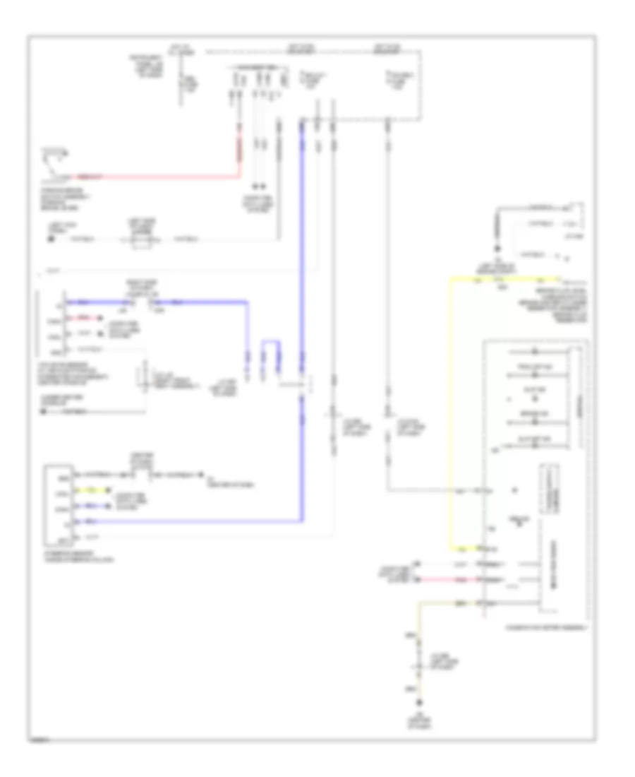
DEFOGGERS
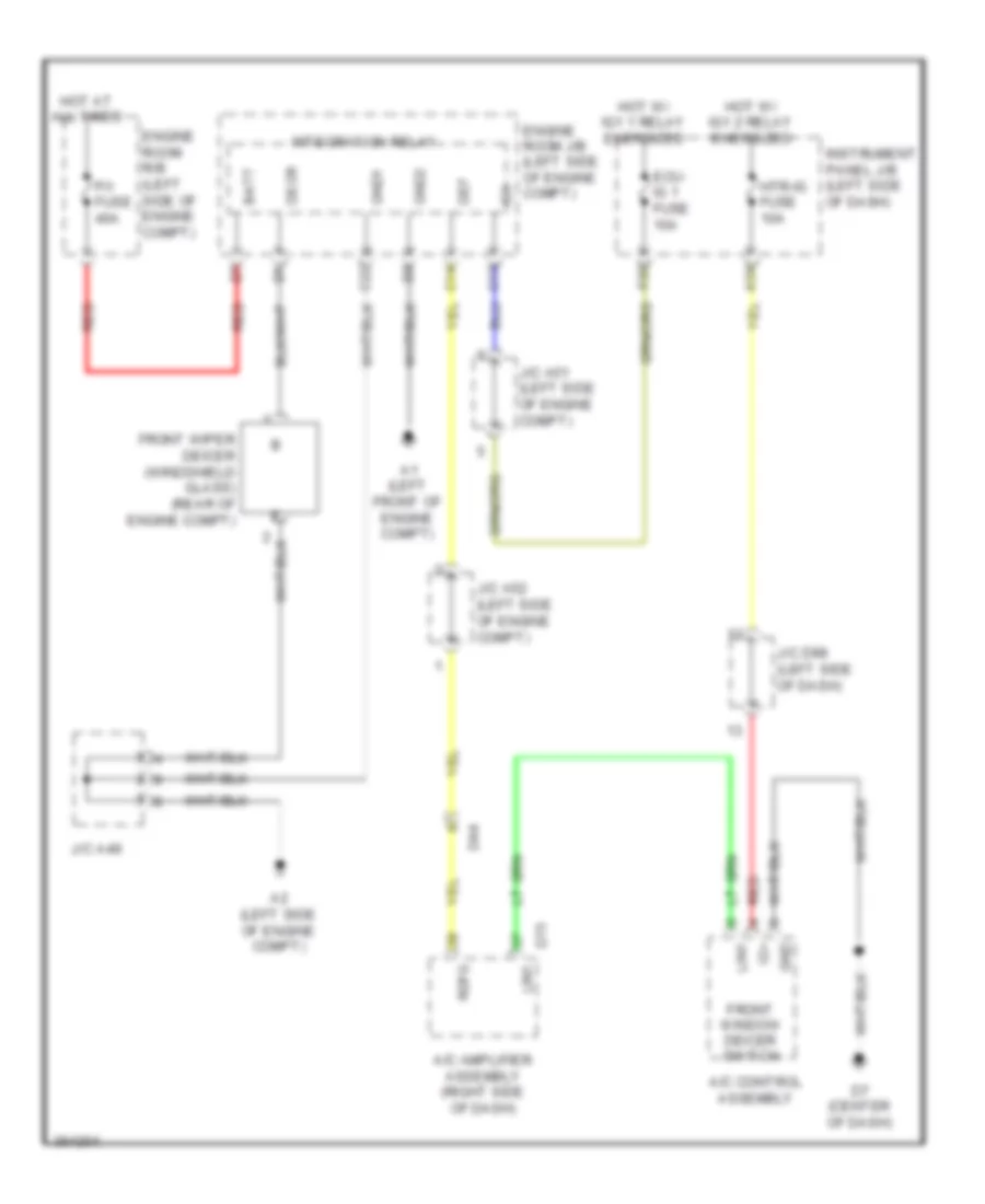
Front Deicer Wiring Diagram for Toyota Sienna 2013
List of elements for Front Deicer Wiring Diagram for Toyota Sienna 2013:
- A/c amplifier assembly (right side of dash)
- A/c control assembly
- A1 (left front of engine compt)
- A2 (left side of engine compt)
- A54
- Batt
- C13
- C14
- C22
- D7 (center of dash)
- D75
- Da4
- Decr
- Def
- Ecu- ig 1 fuse 10a
- Engine room j/b (left side of engine compt)
- Engine room r/b (left side of engine compt)
- F33
- Front window deicer switch
- Front wiper deicer (windshield glass) (rear of engine compt)
- Gnd
- Gnd1
- Gnd2
- Hot at all times
- Hot w/ ig1 1 relay energized
- Hot w/ ig1 2 relay energized
- Htr-ig fuse 10a
- Ig+
- Ig1
- Instrument panel j/b (left side of dash)
- Integration relay
- J/c a49
- J/c a51 (left side of engine compt)
- J/c a52 (left side of engine compt)
- J/c d98 (left side of dash)
- Lin1
- P/i fuse 40a
- Rdfg
- Red
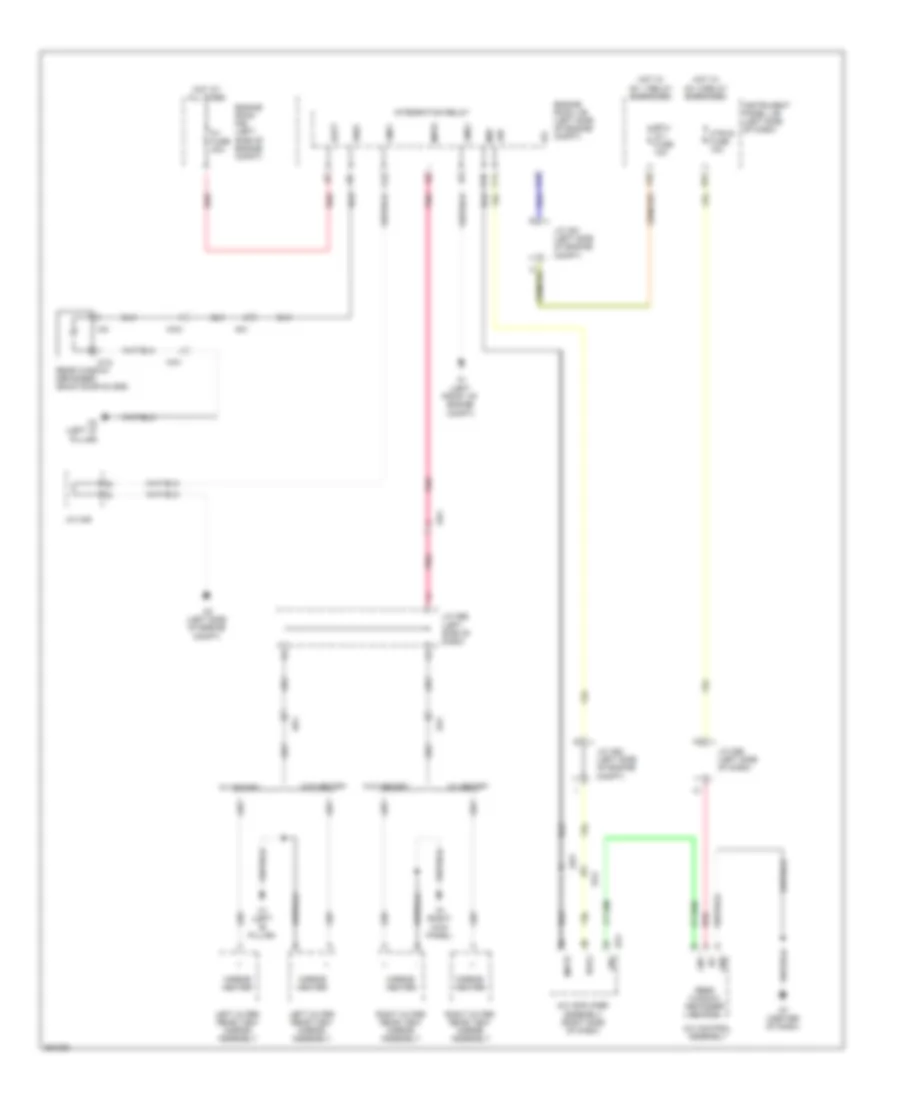
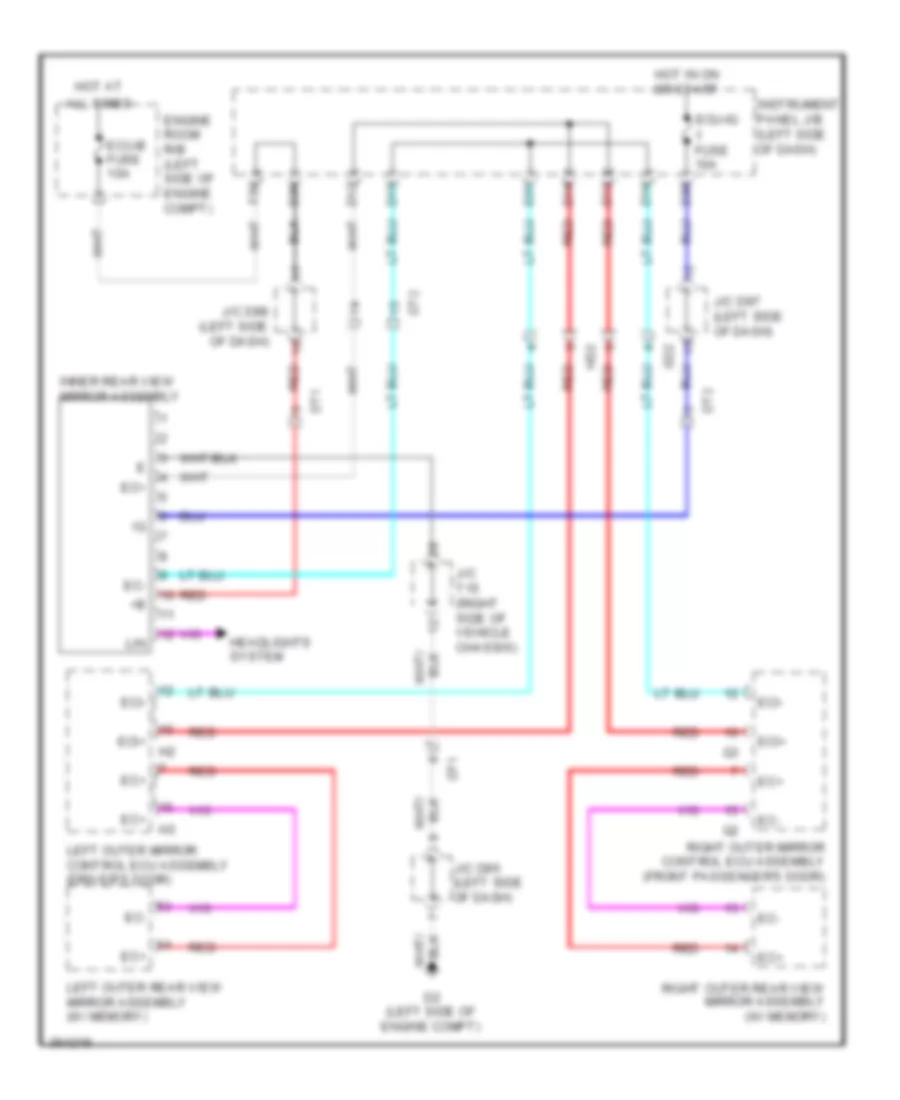
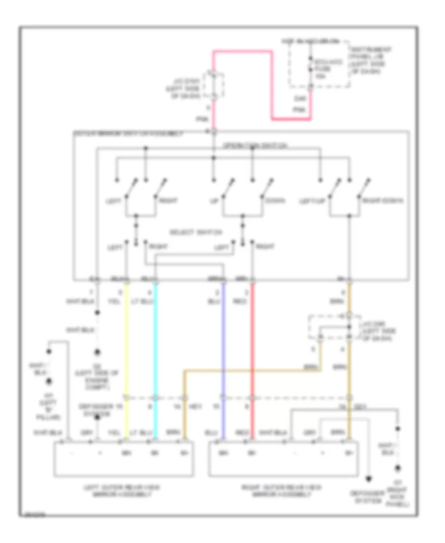
Mirror Heater & Rear Defogger Wiring Diagram for Toyota Sienna 2013
List of elements for Mirror Heater & Rear Defogger Wiring Diagram for Toyota Sienna 2013:
- A/c amplifier assembly (right side of dash)
- A/c control assembly
- A1 (left front of engine compt)
- A2 (left side of engine compt)
- A54
- Ad3
- Ad4
- Batt
- C13
- C14
- C16
- C22
- D7 (center of dash)
- D75
- Da4
- Def
- Ecu- ig 1 fuse 10a
- Engine room j/b (left side of engine compt)
- Engine room r/b (left side of engine compt)
- F33
- G1 (right kick panel)
- Gd1
- Gnd
- Gnd1
- Gnd2
- H1 (left "b" pillar)
- Hd1
- Hot at all times
- Hot w/ ig1 1 relay energized
- Hot w/ ig1 2 relay energized
- Htr-ig fuse 10a
- Ig+
- Ig1
- Instrument panel j/b (left side of dash)
- Integration relay
- J/c a49
- J/c a51 (left side of engine compt)
- J/c a52 (left side of engine compt)
- J/c d96 (left side of dash)
- J/c d98 (left side of dash)
- K4 (left "d" pillar)
- Ka1
- Left outer rear view mirror assembly
- Lin1
- Mht
- Mhtr
- Mirror heater
- P/i fuse 40a
- Pnk
- Rdef
- Rdfg
- Rear window defogger (back door glass)
- Rear window defogger switch
- Red
- Right outer rear view mirror assembly
- W/ memory
- W/o memory
- W18
- Wk1
- Wk3
ELECTRONIC POWER STEERING
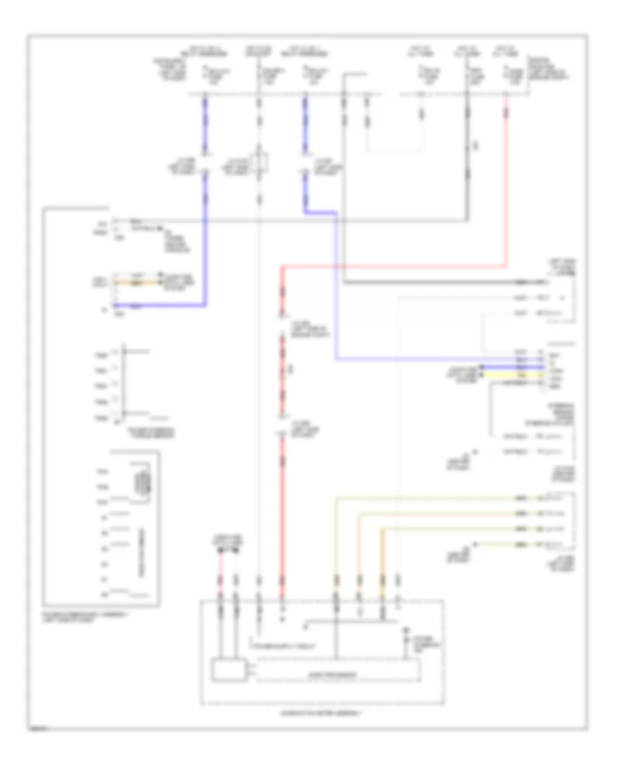
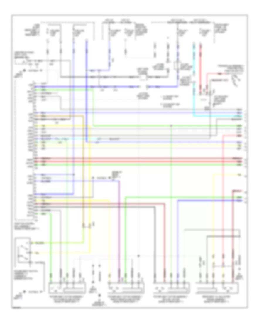
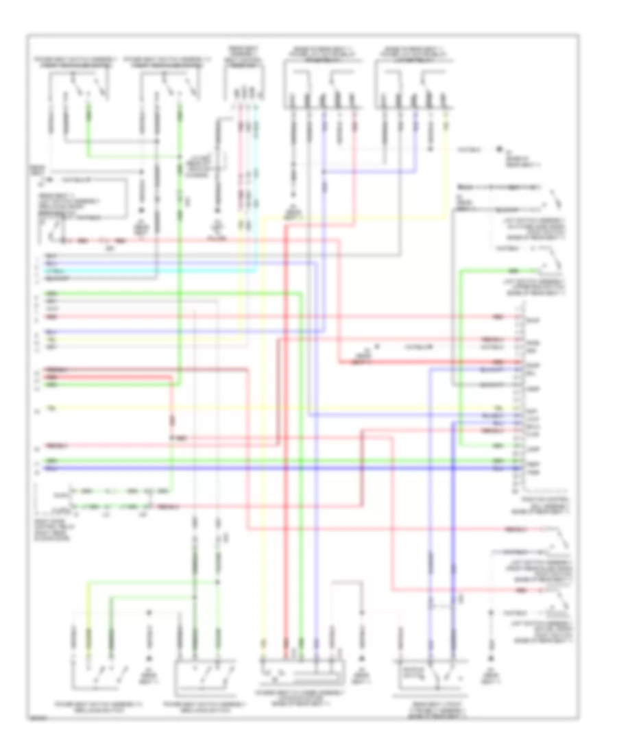
Electronic Power Steering Wiring Diagram for Toyota Sienna 2013
List of elements for Electronic Power Steering Wiring Diagram for Toyota Sienna 2013:
- (left side of dash) j/c d98
- A35
- A55
- Ad1
- Ad4
- Bat
- Can l can h
- Canh
- Canl
- Combination meter assembly
- Computer data lines system
- D35
- D36
- D38
- D5 (under center console)
- D6 (center of dash)
- D7 (center of dash)
- Dome fuse 7.5a
- Ecu-b fuse 10a
- Ecu-ig 1 fuse 10a
- Ecu-ig 2 fuse 10a
- Engine room r/b (left side of engine compt)
- Eps fuse 60a
- Ess
- F39
- Gauge 2 fuse 7.5a
- Hot at all times
- Hot in on or start
- Hot w/ ig1 1 relay energized
- Hot w/ ig1 2 relay energized
- Ig+
- Ig2
- Instrument panel j/b (left side of dash)
- J/c a52 (left side of engine compt)
- J/c d100 (left side of dash)
- J/c d105 (center of dash)
- J/c d96 (left side of dash)
- J/c d97 (left side of dash)
- J/c d99 (left side of dash)
- Lcl-
- Mgnd
- Micro processor
- Pgnd
- Pha
- Phb
- Phc
- Pig
- Pnk
- Power steering ecu assembly (left side of dash)
- Power steering ind
- Power steering motor
- Power steering torque sensor
- Red
- Resolver sensor
- Steering sensor (inside steering column)
- Trq1
- Trq2
- Trqf
- Trqg
- Trqv
ENGINE PERFORMANCE
2.7L
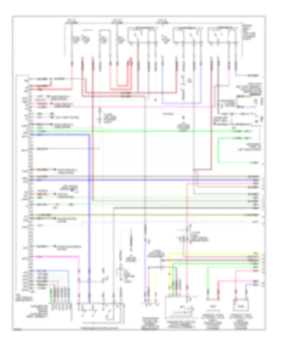
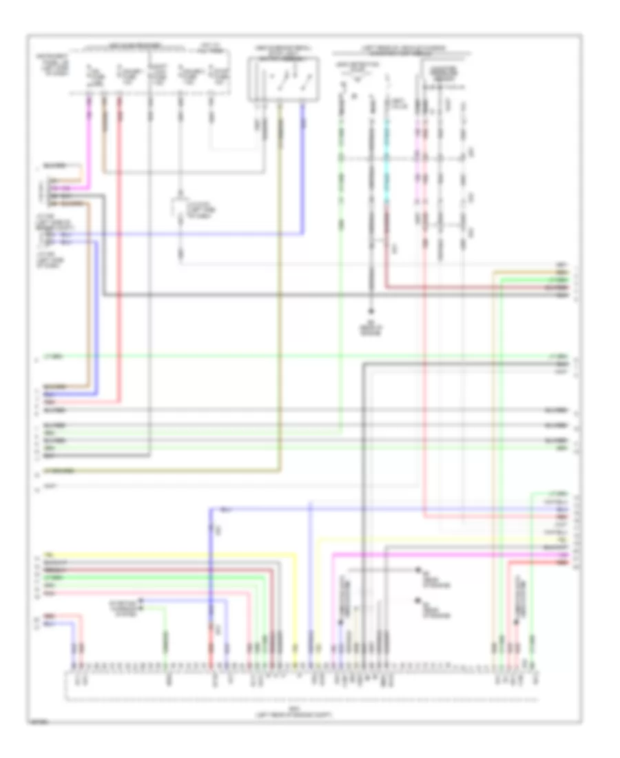
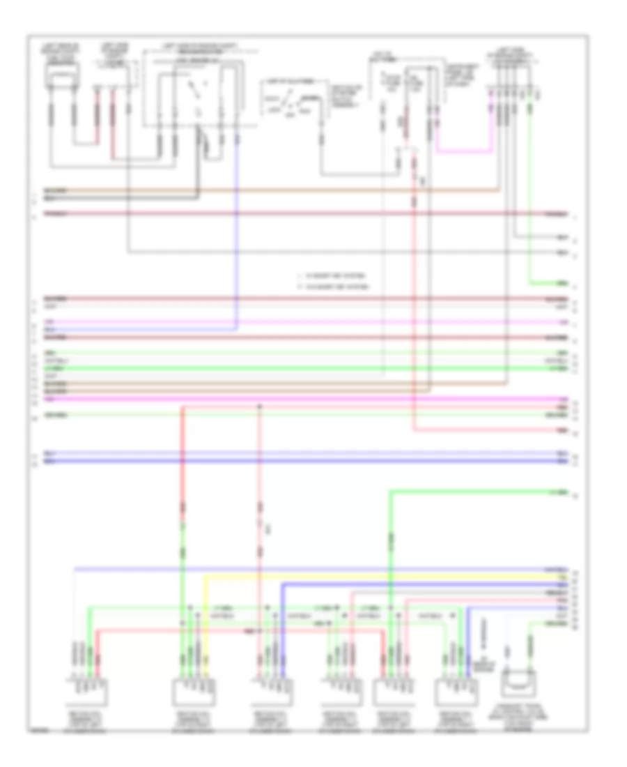
2.7L, Engine Performance Wiring Diagram (1 of 4) for Toyota Sienna 2013
List of elements for 2.7L, Engine Performance Wiring Diagram (1 of 4) for Toyota Sienna 2013:
- (fuel pump: fuel tank assembly) fuel pump & fuel sender gauge assembly
- (left side of engine compt)
- (under left front seat) k1
- +b2
- +bm
- A/f fuse 20a
- A/f htr relay
- A2 (left side of engine compt)
- A30
- A46
- A55
- Accelerator position sensor (accelerator pedal assembly)
- Ad4
- Anti-theft system
- Ba2
- Batt
- C/opn relay
- Camshaft timing oil control valve (bank 1 exhaust side) (top front of engine)
- Camshaft timing oil control valve (bank 1 intake side) (top front of engine)
- Canh
- Canl
- Ccs
- Computer data lines system
- Cooling fans system
- Cruise control system
- D7 (center of dash)
- Ecm (left rear of engine compt)
- Ect fuse 7.5a
- Efi 1 fuse 25a
- Efi 2 fuse 10a
- Efi main relay
- Engine room r/b (left side of engine compt)
- Epa
- Epa2
- Etcs fuse 10a
- F34
- Gauge
- Hot at all times
- Igsw
- Imi
- Imo
- Instrument cluster system
- Instrument panel j/b (left side of dash)
- J/c a46 & b44 (left side of engine compt) b44
- J/c a46 (left side of engine compt)
- J/c a49
- J/c b44 (left side of engine compt)
- J/c d105 (center of dash)
- Ka2
- Mpmp
- Mrel
- Park/neutral position switch assembly (transaxle assembly)
- Pnk
- Pump
- Red
- Rfl
- Sftd
- Sftu
- Spd
- St-
- Sta
- Starting/charging system
- Stp
- Tach
- Transmission control ecu assembly (left front of engine compt)
- Transmission control switch
- Vcp2
- Vcpa
- Vpa
- Vpa2
- Vpmp
- Gk1
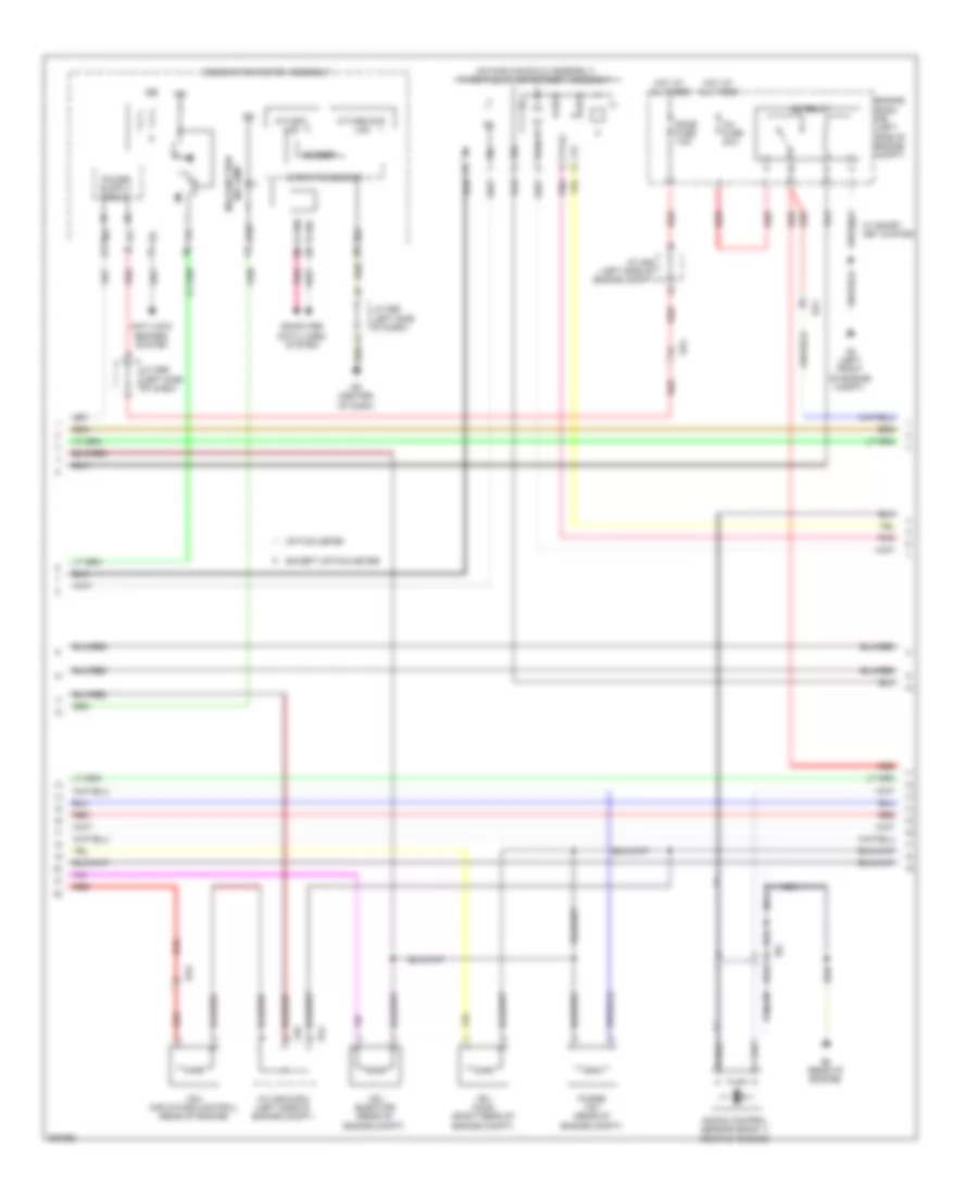
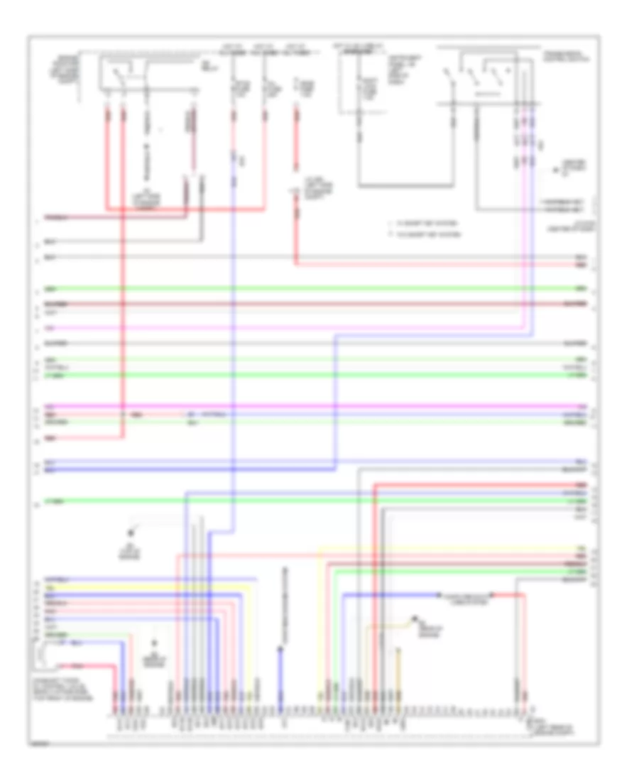
2.7L, Engine Performance Wiring Diagram (2 of 4) for Toyota Sienna 2013
List of elements for 2.7L, Engine Performance Wiring Diagram (2 of 4) for Toyota Sienna 2013:
- (above brake pedal) stop light switch assembly
- (left rear of vehicle chassis)
- A44
- A55
- Acis
- Ad4
- Aicv
- Alt
- B4 (rear of engine)
- B45
- B5 (rear of engine)
- Ba1
- Ba2
- Can+
- Can-
- Canister pressure sensor
- Canister pump module
- Computer data lines system
- E04
- Ecm (left rear of engine compt)
- F26
- F29
- F35
- F36
- Gauge 1 fuse 10a
- Gauge 2 fuse 7.5a
- Ge01
- Ha1a
- Hot at all times
- Hot in on or start
- Ht1b
- Ia1+
- Ia1-
- Ig2 fuse 7.5a
- Igf1
- Instrument panel j/b (left side of dash)
- J/c a46 (left side of engine compt)
- J/c a48 (left side of dash)
- J/c d100 (left side of dash)
- Ka2
- Leak detection pump
- Lines system computer data
- Me01
- Mgnd
- Mtrb
- Nsw
- Oc1+
- Oc1-
- Oe1+
- Oe1-
- Pbv
- Pnk
- Prg
- Red
- Sgnd
- Shift lock fuse 7.5a
- Starting/ charging system
- Stop fuse 10a
- Vcc
- Vent valve
- Vgnd
- Vlvb
- Vout
- Gk2
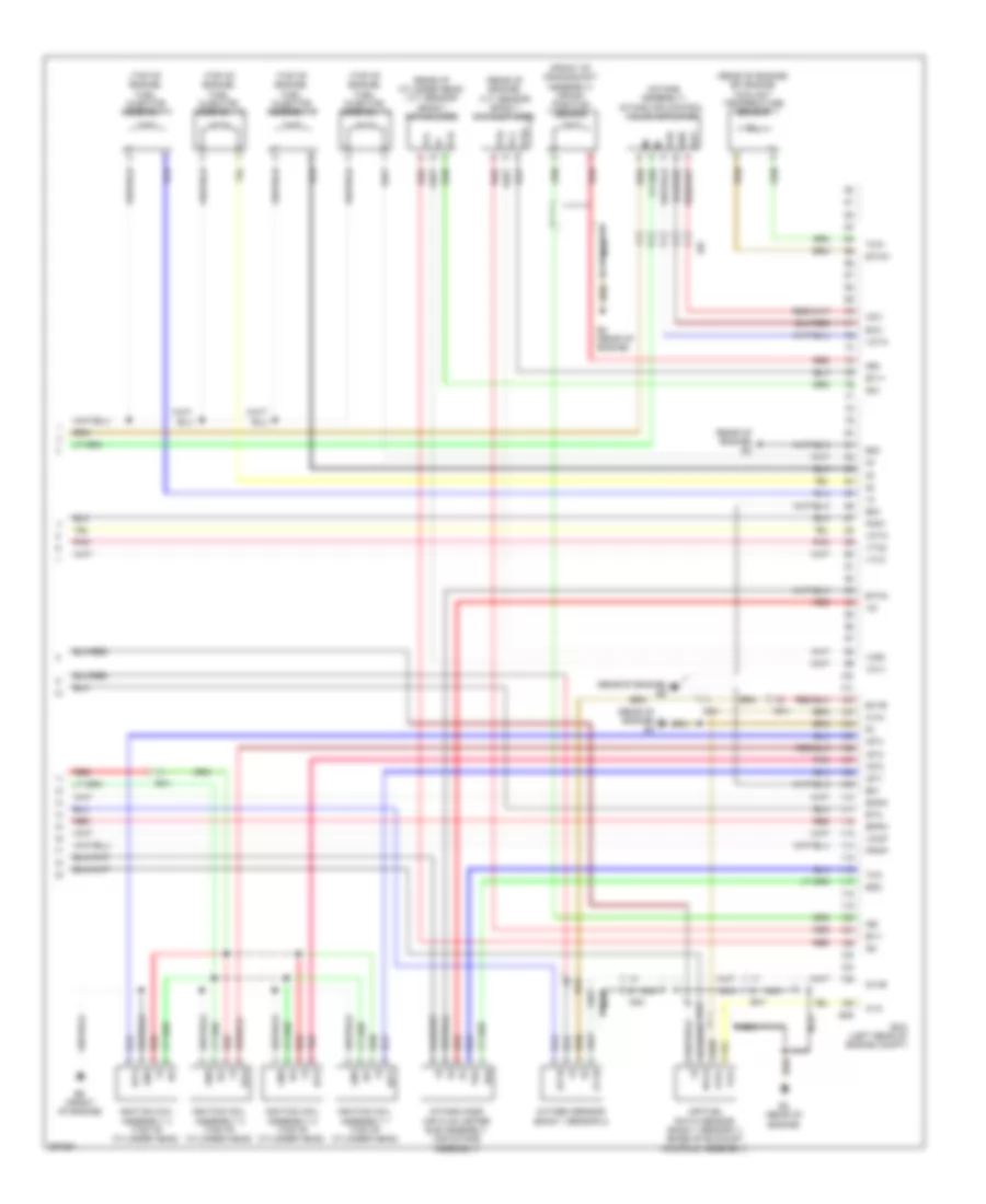
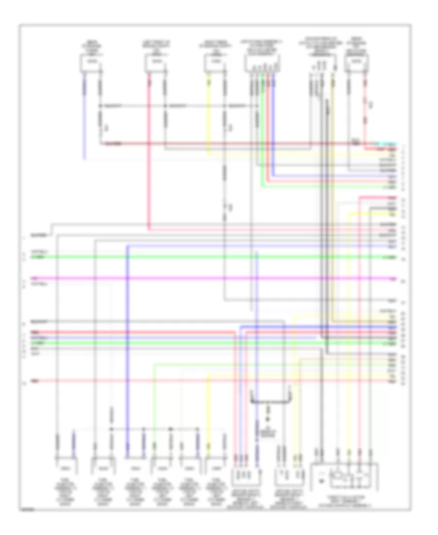
2.7L, Engine Performance Wiring Diagram (3 of 4) for Toyota Sienna 2013
List of elements for 2.7L, Engine Performance Wiring Diagram (3 of 4) for Toyota Sienna 2013:
- (intake manifold assembly) throttle w/ motor body assembly
- A/t/odo lcd
- A/t/odo/acc lcd
- A2 (left front of engine compt)
- A46
- Ad4
- Anti-lock brakes system
- B4 (rear of engine)
- B44
- Ba1
- Ba2
- Buzzer
- Bf2
- Canh
- Canl
- Chk
- Combination meter assembly
- Computer data lines system
- D6 (center of dash)
- Dome fuse 7.5a
- Engine room r/b (left side of engine compt)
- Except option meter
- Hot at all times
- Ig+
- Ig2
- Ig2 relay
- Ind lamp malfunction
- Inj fuse 25a
- J/c a46 & b44 (left side of engine compt)
- J/c a52 (left side of engine compt)
- J/c d96 (left side of dash)
- J/c d99 (left side of dash)
- Knock control sensor (bank 1) (rear of engine)
- Micro processor
- Nca
- Option meter
- Pnk
- Purge vsv (rear of engine compt)
- Red
- Vsv (acis) (right rear of engine compt)
- Vsv (air intake control) (rear of engine)
- Vsv (ejector) (rear of engine compt)
- Vta
- Vta2
- W/ smary key system
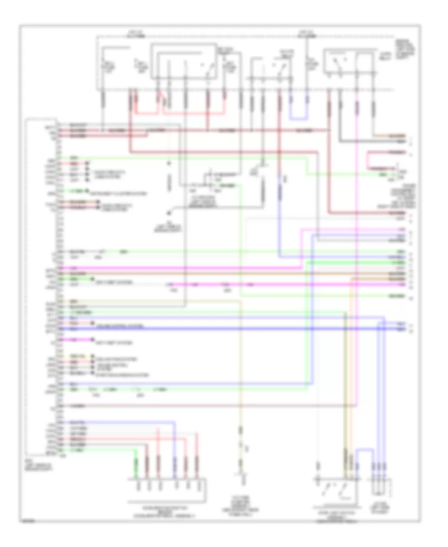
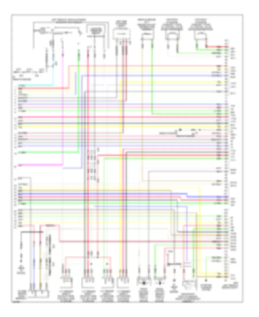
2.7L, Engine Performance Wiring Diagram (4 of 4) for Toyota Sienna 2013
List of elements for 2.7L, Engine Performance Wiring Diagram (4 of 4) for Toyota Sienna 2013:
- (front of crankshaft assembly) crank position sensor
- (front of engine)
- (intake assembly) intake air control valve actuator
- (rear of cylinder head) vvt sensor (bank 1 intake side)
- (rear of engine) b4
- (rear of engine) b5
- (rear of engine) efi engine coolant temperature sensor
- (rear of engine) vvt sensor (bank 1 exhaust side)
- (top of engine) fuel injector assembly 1
- (top of engine) fuel injector assembly 2
- (top of engine) fuel injector assembly 3
- (top of engine) fuel injector assembly 4
- A1a+
- A1a-
- Ad4
- Air fuel ratio sensor (bank 1 sensor 1) (base of exhaust manifold assembly)
- B4 (rear of engine)
- B45
- Ba1
- Ba2
- Ba6
- Bf2
- E01
- E02
- E03
- E2g
- Ecm (left rear of engine compt)
- Eia1
- Eknk
- Eppm
- Eta
- Etha
- Ethw
- Ev1+
- Ev1-
- Ex1b
- G2+
- G2-
- Gnd
- Ht1b
- Iac1
- Igf
- Ignition coil assembly 1 (top of cylinder head)
- Ignition coil assembly 2 (top of cylinder head)
- Ignition coil assembly 3 (top of cylinder head)
- Ignition coil assembly 4 (top of cylinder head)
- Igt1
- Igt2
- Igt3
- Igt4
- Intake mass air flow meter sub assembly (air intake assembly)
- Knk1
- Nca
- Ne+
- Ne-
- Out
- Ox1b
- Oxygen sensor (bank 1 sensor 2)
- Pnk
- Ppmp
- Red
- Tha
- Thw
- Vc2
- Vccp
- Vce1
- Vcta
- Vcv1
- Vdd
- Vta1
- Vta2
- Vve+
- Vve-
- Vvi+
- Vvi-
3.5L
3.5L, Engine Performance Wiring Diagram (1 of 6) for Toyota Sienna 2013
List of elements for 3.5L, Engine Performance Wiring Diagram (1 of 6) for Toyota Sienna 2013:
- +b2
- A/f fuse 20a
- A/f htr relay
- A2 (left side of engine compt)
- A35
- A39
- A46
- Accelerator position sensor (accelerator pedal assembly)
- Ad4
- Anti-theft system
- B44
- Ba2
- Batt
- Canh
- Canl
- Cann
- Canp
- Cchg
- Ccs
- Compt)
- Computer data lines system
- Cooling fans system
- Cruise control system
- Ecm (left rear of engine compt)
- Ect fuse 7.5a
- Efi 1 fuse 25a
- Efi 2 fuse 10a
- Efi main relay
- Els2
- Engine room r/b (left side of engine c/opn relay
- Epa
- Epa2
- Excd
- Fpr
- Hot at all times
- Ig2d
- Igsw
- Imi
- Imo
- Instrument cluster system
- J/c a46 & b44 (left side of engine compt)
- J/c a48 (left side of dash)
- J/c a49
- Ka2
- La1
- Lgnd
- Mpmp
- Mrel
- Neo
- Pnk
- Power management control ecu (w/ smart key system) (right side of dash)
- Red
- Rfc
- Sftd
- Sftu
- Spd
- St1-
- Sta
- Starting/charging system
- Stop light switch assembly (above brake pedal)
- Stp
- Tach
- Vcp2
- Vcpa
- Voltage inverter assembly (above right rear wheelwell)
- Vpa
- Vpa2
- Vpmp
- Gk2
3.5L, Engine Performance Wiring Diagram (2 of 6) for Toyota Sienna 2013
List of elements for 3.5L, Engine Performance Wiring Diagram (2 of 6) for Toyota Sienna 2013:
- (left rear of engine compt) fuel pump resistor
- (left side of engine compt) engine room r/b
- (left side of engine compt) j/c a46 & b44
- (left side of engine compt) j/c a50
- A14
- A46
- Acc
- Ad2
- B1 (rear of engine)
- B44
- Ba1
- Camshaft timing oil control valve (bank 2 exhaust side) (top front of engine)
- F29
- F35
- F36
- Fuel pmp relay
- Gnd
- Hot at all times
- Ig2 fuse 7.5a
- Igf
- Ignition coil assembly 1 (top of right cylinder bank)
- Ignition coil assembly 2 (top of left cylinder bank)
- Ignition coil assembly 3 (top of right cylinder bank)
- Ignition coil assembly 4 (top of left cylinder bank)
- Ignition coil assembly 5 (top of right cylinder bank)
- Ignition coil assembly 6 (top of left cylinder bank)
- Ignition or starter switch assembly
- Igt1
- Igt2
- Igt3
- Igt4
- Igt5
- Igt6
- Instrument panel j/b (left side of dash)
- Lock
- Off
- Pnk
- Red
- Run
- Start
- Stop fuse 10a
- W/ smart key system
- W/o smart key system
3.5L, Engine Performance Wiring Diagram (3 of 6) for Toyota Sienna 2013
List of elements for 3.5L, Engine Performance Wiring Diagram (3 of 6) for Toyota Sienna 2013:
- (center of dash) d7
- +bm
- A2 (left side of engine compt)
- A44
- Ad4
- Alt
- B2 (rear of engine)
- B3 (top of engine)
- Ba1
- Ba2
- Camshaft timing oil control valve (bank 2 intake side) (top front of engine)
- Can+
- Can-
- Computer data lines system
- Dome fuse 7.5a
- Ecm (left rear of engine compt)
- Engine room r/b (left side of engine compt)
- Eo1
- Eo2
- Eo3
- Eo4
- Eo5
- Etcs fuse 10a
- Ge01
- Ha1a
- Ha2a
- Hot at all times
- Hot w/ ig1 2 relay energized
- Ht1b
- Ht2b
- Ig2 relay
- Igt1
- Igt2
- Igt3
- Igt4
- Igt5
- Igt6
- Inj fuse 25a
- Instrument panel j/b (left side of dash)
- J/c a52 (left side of engine compt)
- J/c d105 (center of dash)
- Oc2+
- Oc2-
- Oe2+
- Oe2-
- Pnk
- Red
- Shift lock fuse 7.5a
- Starting/charging system
- Transmission control switch
- W/ smart key system
- W/o smart key system
3.5L, Engine Performance Wiring Diagram (4 of 6) for Toyota Sienna 2013
List of elements for 3.5L, Engine Performance Wiring Diagram (4 of 6) for Toyota Sienna 2013:
- (fuel pump: fuel tank assembly) fuel pump & fuel sender gauge assembly
- A/t/odo lcd
- A46
- A55
- Ad4
- Ba2
- Batt
- Buzzer
- Combination meter assembly
- Computer data lines system
- D6 (center of dash)
- Except optitron meter
- F26
- Gauge
- Gauge 1 fuse 10a
- Gauge 2 fuse 7.5a
- Hot in on or start
- Hot w/ ig1 1 relay energized
- Ig2
- Igsw
- Instrument cluster system
- Instrument panel j/b (left side of dash)
- J/c a46 & b44 (left side of engine b44 compt)
- J/c b44 (left side of engine compt)
- J/c d100 (left side of dash)
- J/c d96 (left side of dash)
- J/c d99 (left side of dash)
- K1 (under left front seat)
- Ka2
- Lcd (a/t/odo lcd)
- Malfunction ind lamp
- Micro processor
- Optitron meter
- Park/neutral position switch assembly (w/o smart key) (transaxle assembly)
- Pnk
- Pump
- Red
- Starting/ charging system
- Stp
- Transmission control ecu assembly (left front of engine compt)
- Gk1
3.5L, Engine Performance Wiring Diagram (5 of 6) for Toyota Sienna 2013
List of elements for 3.5L, Engine Performance Wiring Diagram (5 of 6) for Toyota Sienna 2013:
- (air intake assembly) intake mass air flow meter sub assembly
- (downstream of catalytic converter) oxygen sensor (bank 2 sensor 2)
- (intake manifold assembly)
- (left front of engine compt) vsv (acm)
- (rear of engine) purge vsv
- (rear of engine) vsv (air intake control)
- (right rear of engine compt)
- A1a+
- A1a-
- A2a+
- A2a-
- Air fuel ratio sensor (bank 1 sensor 1) (base of right exhaust manifold)
- Air fuel ratio sensor (bank 2 sensor 1) (base of left exhaust manifold)
- B1 (rear of engine)
- Ba1
- Ba2
- Bank)
- Da6
- E2g
- Fuel injector assembly 1 (top of right cylinder
- Fuel injector assembly 2 (top of left cylinder
- Fuel injector assembly 3 (top of right cylinder
- Fuel injector assembly 4 (top of left cylinder
- Fuel injector assembly 5 (top of right cylinder
- Fuel injector assembly 6 (top of left cylinder
- Ha1a
- Ha2a
- Ht2b
- Ka2
- Nca
- Ox2b
- Pnk
- Red
- Tha
- Throttle w/ motor body assembly
- Vsv (acis)
3.5L, Engine Performance Wiring Diagram (6 of 6) for Toyota Sienna 2013
List of elements for 3.5L, Engine Performance Wiring Diagram (6 of 6) for Toyota Sienna 2013:
- (left rear of vehicle chassis) canister pump module
- (left side of engine compt) j/c a46 & b44
- (rear of engine) e.f.i engine coolant temperature sensor
- (top front of engine)
- (top front of engine) camshaft timing oil control valve (bank 1 exhaust side)
- (top front of engine) camshaft timing oil control valve (bank 1 intake side)
- A1a+
- A1a-
- A2a+
- A2a-
- A46
- Acis
- Acm
- Ad4
- Aicv
- B1 (rear of engine)
- B2 (rear of engine)
- B44
- Ba1
- Ba2
- Bf1
- Canister pressure sensor
- Crankshaft position sensor (front of crankshaft assembly)
- E2g
- Ecm (left rear of engine compt)
- Ekn2
- Eknk
- Eta
- Etha
- Ethw
- Ev1+
- Ev2+
- Ex+
- Ex-
- Ex1b
- Ex2b
- Ht1b
- Igf1
- Ka2
- Knk1
- Knk2
- Knock control sensor (bank 1) (top of engine)
- Knock control sensor (bank 2) (top of engine)
- Leak detection pump
- Meo1
- Nca
- Ne+
- Ne-
- Nsw
- Oc1+
- Oc1-
- Oe1+
- Oe1-
- Ox1b
- Ox2b
- Oxygen sensor (bank 1 sensor 2)
- Pnk
- Ppmp
- Prg
- Red
- Starting/ charging system
- Tha
- Thw
- Valve vent
- Vc2
- Vcta
- Vcv1
- Vcv2
- Vta1
- Vta2
- Vv1+
- Vv1-
- Vv2+
- Vv2-
- Vvl+
- Vvl-
- Vvr+
- Vvr-
- Vvt sensor (bank 1 exhaust side) (top left side of engine)
- Vvt sensor (bank 1 intake side)
- Vvt sensor (bank 2 exhaust side) (top right side of engine)
- Vvt sensor (bank 2 intake side) (top front of engine)
- Gk2
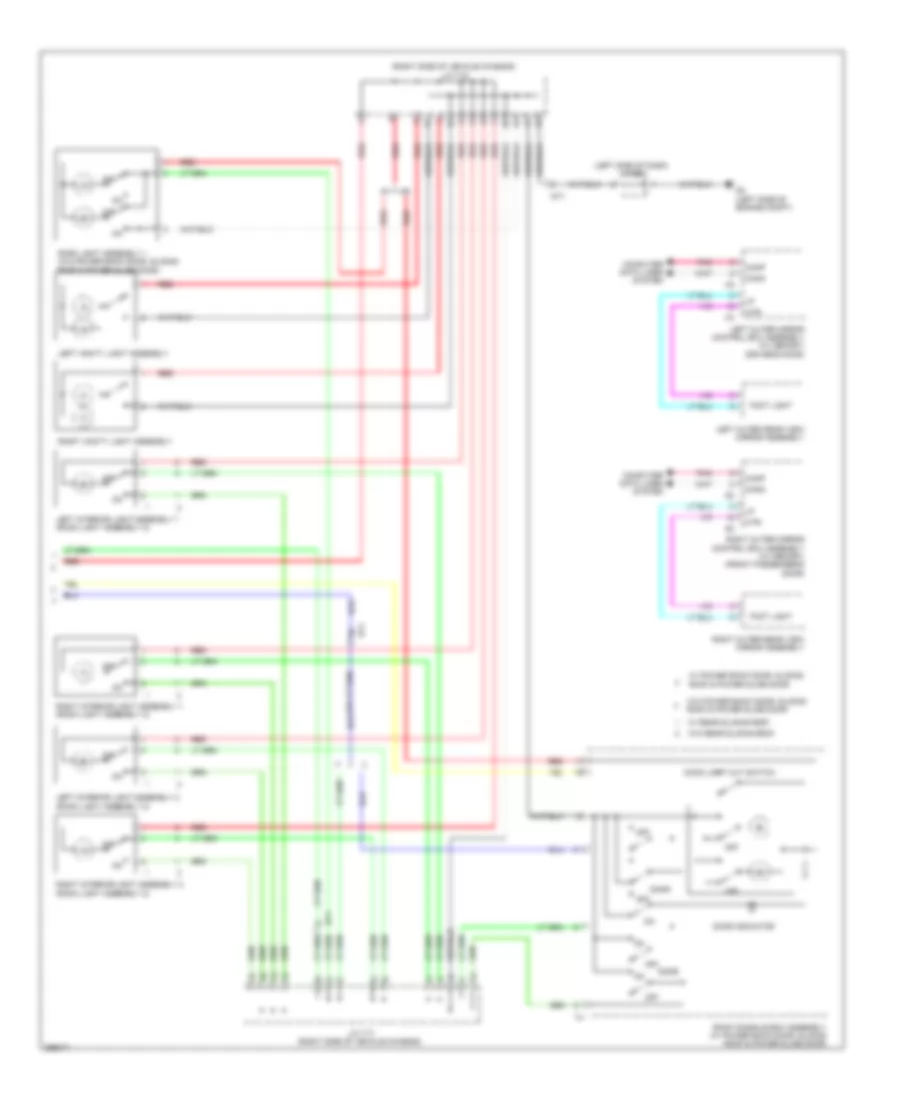
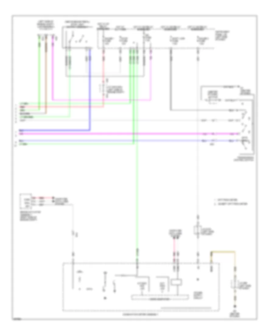
EXTERIOR LIGHTS
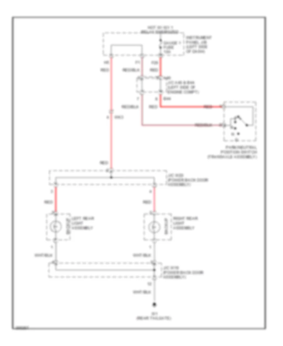
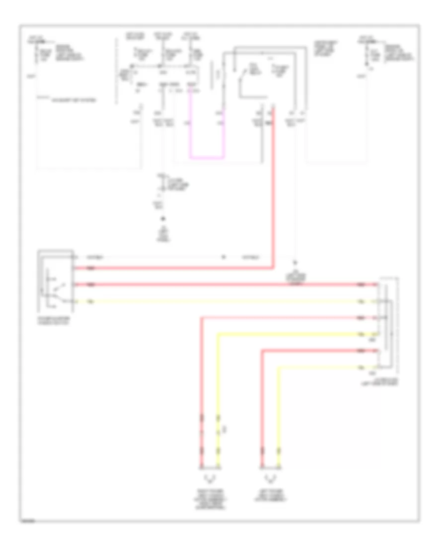
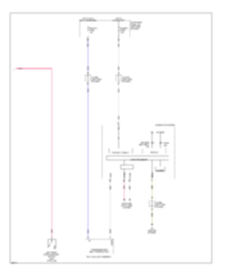
Backup Lamps Wiring Diagram for Toyota Sienna 2013
List of elements for Backup Lamps Wiring Diagram for Toyota Sienna 2013:
- A46
- B44
- Backup
- F26
- Gauge 1 fuse 10a
- Hot w/ ig1 1 relay energized
- Instrument panel j/b (left side of dash)
- J/c a46 & b44 (left side of engine compt)
- J/c w19 (power back door assembly)
- J/c w20 (power back door assembly)
- Left rear light assembly
- Park/neutral position switch (transaxle assembly)
- Red
- Right rear light assembly
- W1 (rear tailgate)
- Wk3
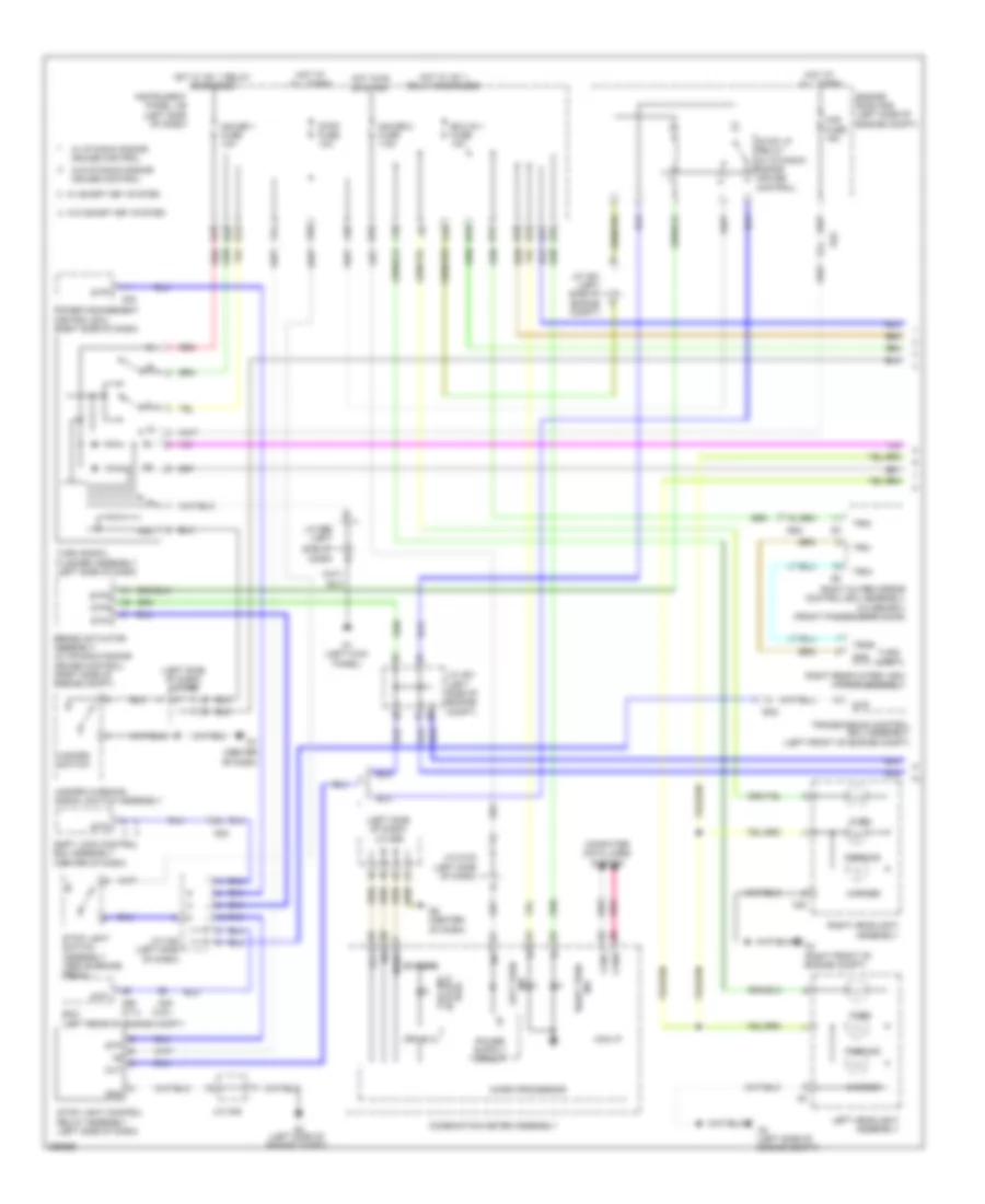
Exterior Lamps Wiring Diagram (1 of 2) for Toyota Sienna 2013
List of elements for Exterior Lamps Wiring Diagram (1 of 2) for Toyota Sienna 2013:
- (3.5l)
- (center of dash)
- (left side of dash) j/c d96
- A2 (left side of engine compt)
- A22
- A23
- A3 (right front of engine compt)
- A35
- A39
- A55
- A55 (2.7l)
- Ad2
- Ad3
- B+ dome
- Ba2
- Brake actuator assembly (w/ dynamic radar cruise control) (right side of engine compt)
- Can i/f
- Canh
- Canl
- Combination meter assembly
- Compt)
- Computer data lines system
- D1 (left kick panel)
- D20
- D24
- D25
- D33
- D34
- D39
- D6 (center of dash)
- Drive ic
- Ecm (left rear of engine compt)
- Ecu-ig 1 fuse 10a
- Engine room r/b (left side of engine compt)
- F10
- F29
- F30
- F31
- F33
- Gauge 1 fuse 10a
- Gauge 2 fuse 7.5a
- Gd2
- Gnd
- H19
- H31
- Hal
- Haz fuse 15a
- Hazard switch
- Hazard warning signal switch assembly
- Hot at all times
- Hot in on or start
- Hot w/ ig1 1 relay energized
- Ig+
- Ind left turn
- Instrument panel j/b (left side of dash)
- J/c a48 (left side of dash)
- J/c a49
- J/c a51 (left side of engine
- J/c a51 (left side of engine compt)
- J/c d100 (left side of dash)
- J/c d99 (left
- Lcl-
- Left headlight assembly
- Marker
- Mgnd
- Micro processor
- Out
- Parking
- Pnk
- Power management control ecu (right side of dash)
- Red
- Right headlight assembly
- Right outer mirror control ecu assembly (w/ memory) (front passenger's door)
- Right rear outer view mirror assembly
- Right turn ind
- Shift lock control ecu assembly (center of dash)
- Side of dash)
- Stop fuse 10a
- Stop light control relay assembly (left side of dash)
- Stop light switch assembly (above brake pedal)
- Stop lp relay (w/ dynamic radar cruise control)
- Stp
- Stp1
- Stp2
- Stpo
- Tail ind
- Transmission control ecu assembly (left front of engine compt)
- Trn+
- Trn-
- Trni
- Trnr
- Turn
- Turn light
- Turn signal flasher assembly (left side of dash)
- Usa) (except
- W/ dynamic radar cruise control
- W/ smart key system
- W/o dynamic radar cruise control
- W/o smart key system
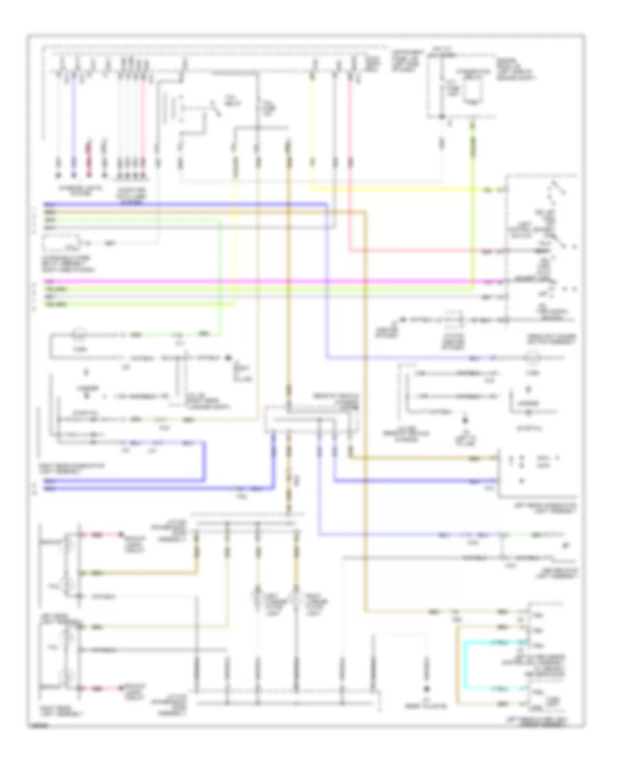
Exterior Lamps Wiring Diagram (2 of 2) for Toyota Sienna 2013
List of elements for Exterior Lamps Wiring Diagram (2 of 2) for Toyota Sienna 2013:
- (rear of vehicle chassis) j/c k28
- A37
- Alt fuse 140a
- Backup
- Backup lamps circuit
- Canh
- Canl
- Center stop light assembly
- Computer data lines system
- D12
- D13
- D17
- D7 (center of dash)
- Dl6
- Drl (usa) auto (except usa)
- Drl off (usa) off (except usa)
- Engine room j/b (left side of engine compt)
- F37
- Flcy
- Frcy
- Gnd
- H27
- H30
- H35
- Haz
- Hd2
- Head
- Headlight dimmer switch assembly
- Hot at all times
- Instrument panel j/b (left side of dash)
- Integration relay
- Interior lights system
- J/c d105 (center of dash)
- J/c k29 (rear of vehicle chassis)
- J/c l39 (right rear luggage compt)
- J/c w19 (power back door assembly)
- J/c w20 (power back door assembly)
- K18
- K19
- K3 (left "d" pillar)
- Ka2
- Kl1
- L2 (right "c" pillar)
- L32
- L33
- La1
- Lcty
- Left license plate
- Left outer mirror control ecu assembly (w/ memory) (driver's door)
- Left rear combination light assembly
- Left rear light assembly
- Left rear outer view mirror assembly
- Light
- Light control switch
- Main body ecu
- Marker
- Off
- Pgr
- Pnk
- Rcty
- Rda
- Red
- Right license plate
- Right rear combination light assembly
- Right rear light assembly
- Stop/tail
- Tail
- Tail fuse 10a
- Tail relay
- Trly
- Trn+
- Trn-
- Trni
- Trnl
- Turn
- Turn light
- Turn signal switch
- W1 (rear tailgate)
- Windshield wiper relay assembly (right side of dash)
- Wk2
- Wk3
- Mw1
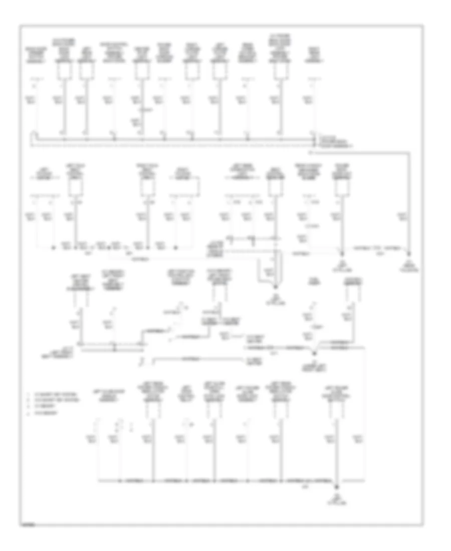
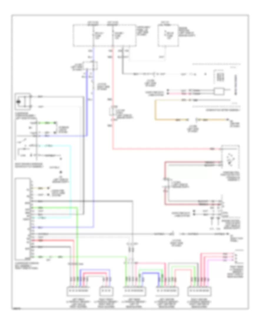
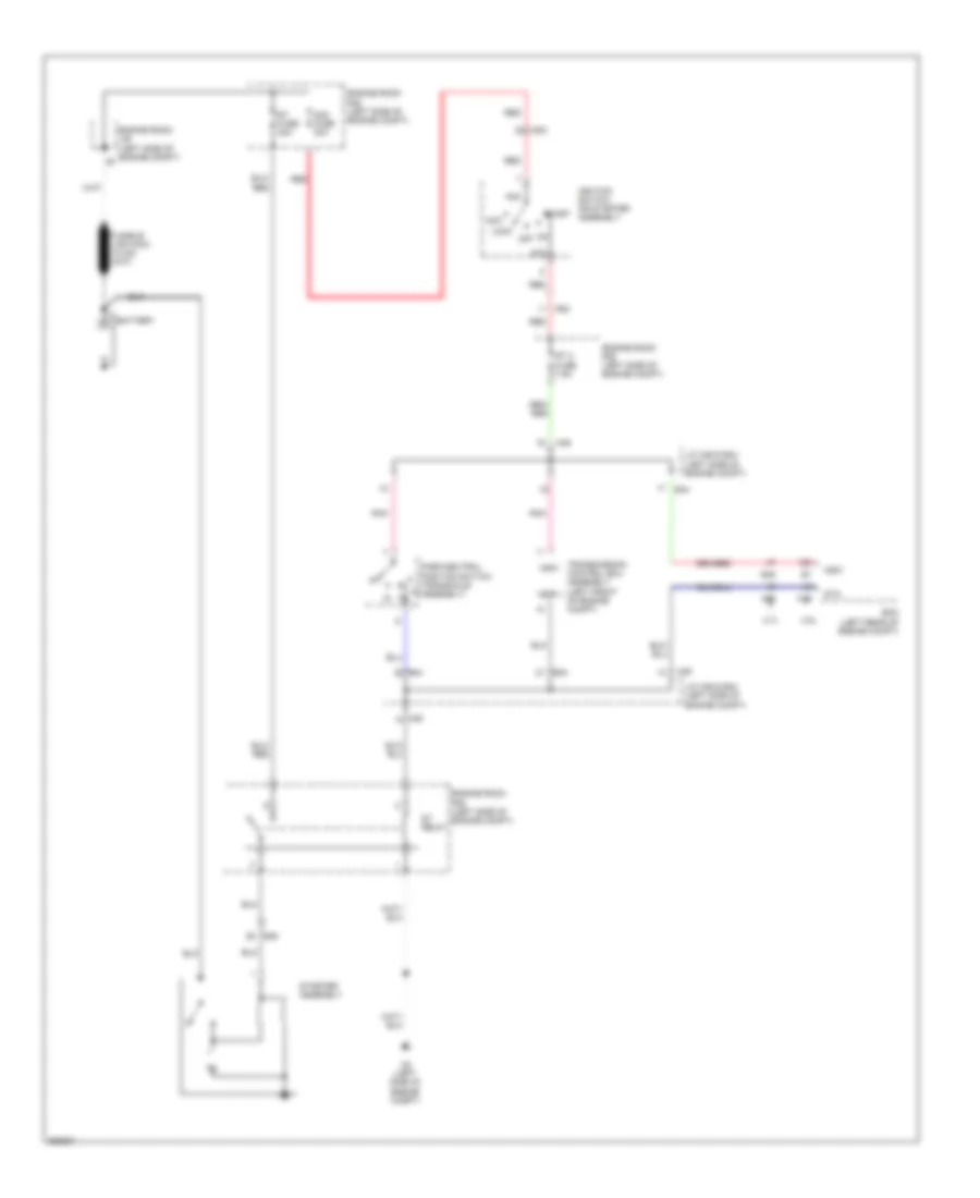
GROUND DISTRIBUTION
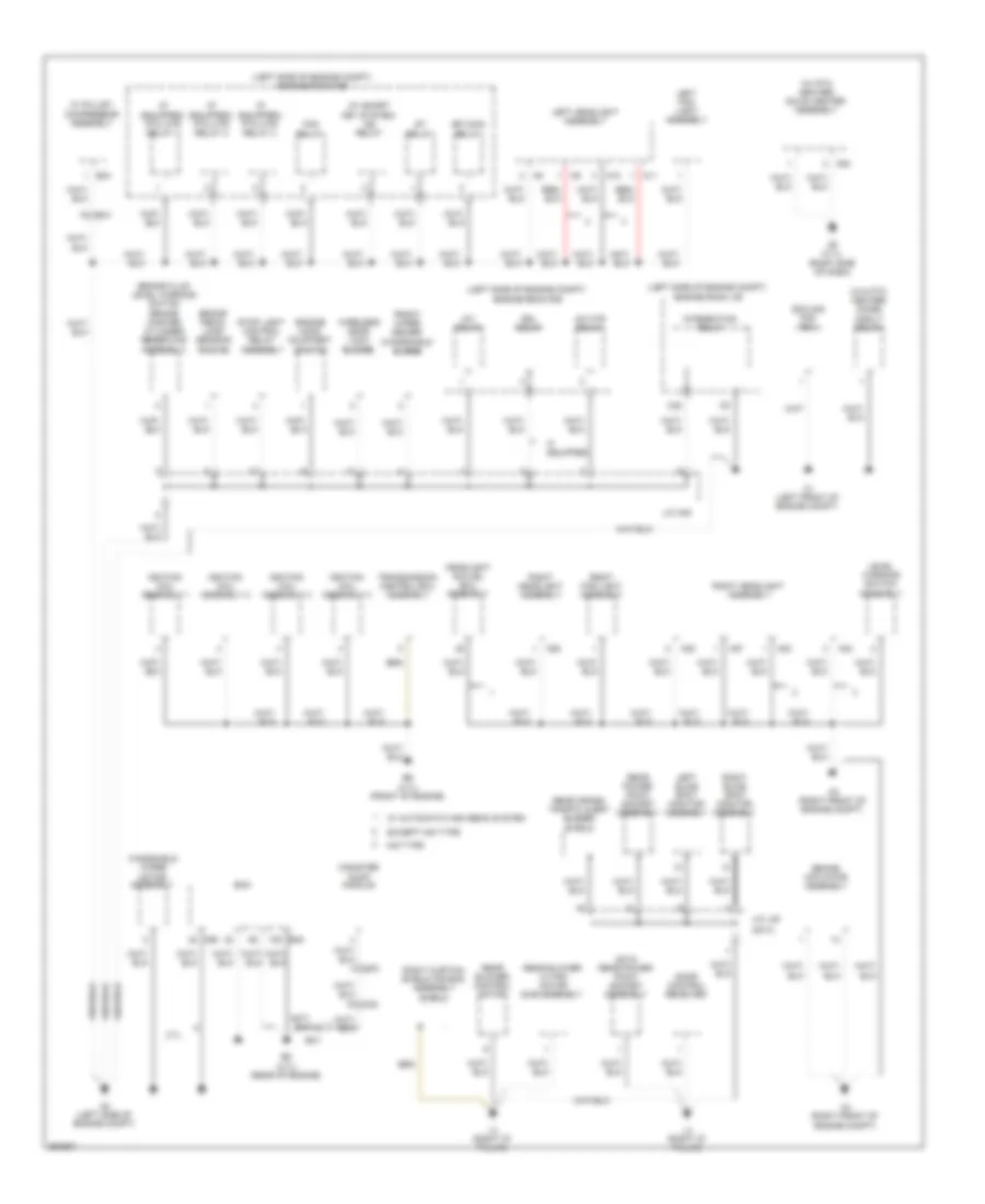
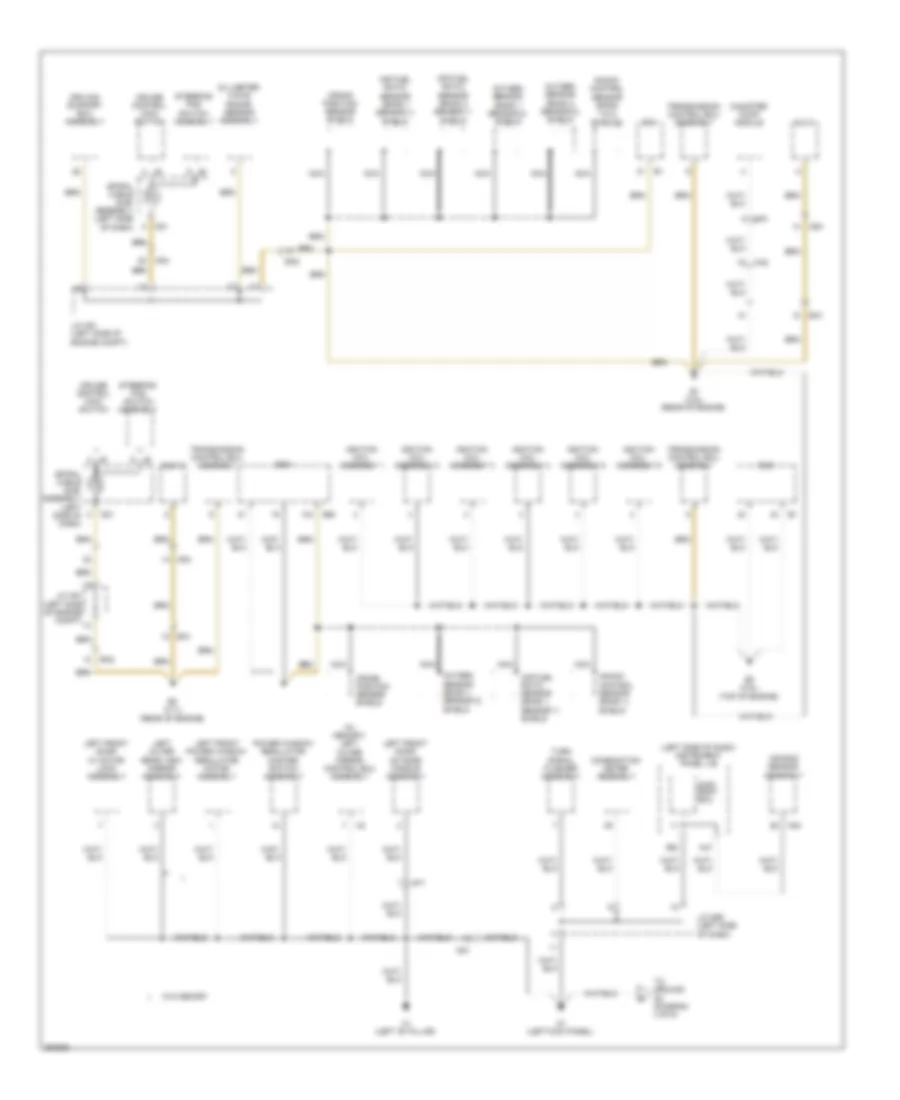
Ground Distribution Wiring Diagram (1 of 6) for Toyota Sienna 2013
List of elements for Ground Distribution Wiring Diagram (1 of 6) for Toyota Sienna 2013:
- (2012) rear power point socket assembly
- (2013)
- (if equipped) ptc htr relay 1
- (if equipped) ptc htr relay 2
- (if equipped) ptc htr relay 3
- (left side of engine compt)
- (left side of engine compt) engine room r/b
- (w/ ptc heater) quick heater assembly
- (w/ smart key system) ig2 relay
- (w/o ptc heater) diode (mgclt relay)
- 2.7l
- A/f htr relay
- A1 (left front of engine compt)
- A10
- A11
- A2 (left side of engine compt)
- A22
- A23
- A24
- A27
- A28
- A3 (right front of engine compt)
- A4 (right front of engine compt)
- A5 (2.7l) (right side of dash)
- A54
- A55
- B34
- B45
- B5 (2.7l) (rear of engine)
- B6 (2.7l) (front of engine)
- Ba1
- Brake actuator assembly
- Brake fluid level warning switch (brake master cylinder reservoir assembly)
- Brake pedal load sensing switch
- C22
- Canister pump module
- Cooling fan ecu
- Door control receiver
- Drl relay
- Ecm
- Efi main relay
- Engine hood courtesy switch
- Engine room j/b
- Engine room r/b
- Except hid type
- Fan relay
- Front wiper deicer (windshield glass)
- Headlight swivel ecu assembly
- Hid type
- If equipped
- Ignition coil assembly 1
- Ignition coil assembly 2
- Ignition coil assembly 3
- Ignition coil assembly 4
- Integration relay
- Inv relay
- J/c a49
- J/c l49
- Ka2
- L3 (right "d" pillar)
- L4 (right "d" pillar)
- Left blind spot monitor assembly
- Left fog light assembly
- Left headlight assembly
- Level warning switch assembly
- Rear blower control motor
- Rear blower w/ fan motor sub-assembly
- Rear cross traffic alert buzzer shield
- Rear power point socket assembly
- Right blind spot monitor assembly
- Right curtain shield air bag assembly shield
- Right fog light assembly
- Right headlight assembly
- St relay
- Stop light control relay assembly
- Transmission control ecu assembly
- W/ automatic high beam system
- W/ pulley compressor assembly
- Windshield wiper motor assembly
- Wireless door lock buzzer
- Gk2
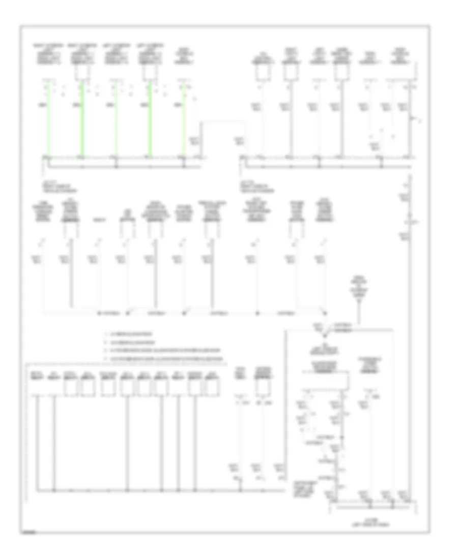
Ground Distribution Wiring Diagram (2 of 6) for Toyota Sienna 2013
List of elements for Ground Distribution Wiring Diagram (2 of 6) for Toyota Sienna 2013:
- (left side of dash) instrument panel j/b
- (w/ memory) left outer mirror control ecu assembly
- A47
- Ad4
- Air bag sensor assembly
- Air fuel ratio sensor (bank 1 sensor 1) shield
- Air fuel ratio sensor (bank 2 sensor 1) shield
- B1 (3.5l) (rear of engine)
- B3 (3.5l) (top of engine)
- B4 (2.7l) (rear of engine)
- B45
- Ba1
- Ba2
- Canister pump module
- Combination meter assembly
- Crank position sensor shield
- Cruise control main switch
- D1 (left kick panel)
- D21
- D32
- D40
- Dlc 3
- Driving support ecu assembly
- Ecm
- H1 (left "b" pillar)
- Hd1
- Ignition coil assembly 1
- Ignition coil assembly 2
- Ignition coil assembly 3
- Ignition coil assembly 4
- Ignition coil assembly 5
- Ignition coil assembly 6
- J/c a51 (left side of engine compt)
- J/c d99 (left side of dash)
- Ka2
- Knock control sensor (bank 1 & 2) shields
- Knock control sensor (bank 1) shield
- Left front door outside handle assembly
- Left front door w/ motor lock assembly
- Left front power window regulator motor assembly
- Left outer rear view mirror assembly
- Main body ecu
- Millimeter wave radar sensor assembly
- Nca
- Oxygen sensor (bank 1 sensor 2) shield
- Oxygen sensor (bank 2 sensor 2) shield
- Power window regulator master switch assembly
- Spiral cable sub- assembly (left side of dash)
- Steering pad switch assembly
- To ground d2 (diagram 3 of 6)
- Transmission control ecu assembly
- Turn signal flasher assembly
- W/o memory
- Gk2
- Ph1
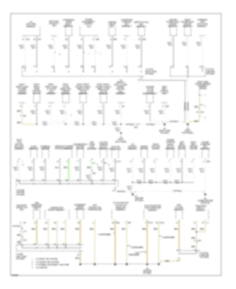
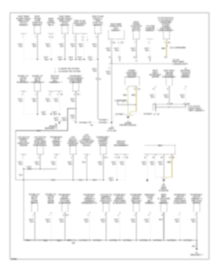
Ground Distribution Wiring Diagram (3 of 6) for Toyota Sienna 2013
List of elements for Ground Distribution Wiring Diagram (3 of 6) for Toyota Sienna 2013:
- (w/ memory) outer mirror switch assembly
- (w/o memory) outer mirror switch assembly
- (w/o smart key system) transponder key ecu assembly
- A/c control assembly 2
- Acc relay
- Air bag sensor assembly
- Back sonar or clearance sonar switch assembly
- Bk d/l relay
- D d/ul relay
- D/l relay
- D/ul relay
- D14
- D2 (left side of engine compt)
- D25
- D40
- Dlc 3
- Dt1
- From ground d1 (diagram 2 of 6)
- Ig1 1 relay
- Ig1 2 relay
- Ig1 3 relay
- Ig1 4 relay
- Inner rear view mirror assembly
- Instrument panel j/b (left side of dash)
- J/c d95 (left side of dash)
- J/c t15 (right side of vehicle chassis)
- J/c t17 (right side of vehicle chassis)
- Left interior light assembly 1 (room light assembly 2)
- Left interior light assembly 2 (room light assembly 2)
- Left vanity light assembly
- Main body ecu
- P/point relay
- P/w main relay
- Power quarter window switch
- Power slide door main switch
- Pre-collision system cancel switch assembly
- Right interior light assembly 1 (room light assembly 2)
- Right interior light assembly 2 (room light assembly 2)
- Right vanity light assembly
- Roof console box assembly
- Room light assembly 1
- Sliding roof drive gear assembly
- Tire pressure warning reset switch
- Tv1
- Vsc off switch
- Vj1
- W/ power back door, sliding roof & power slide door
- W/ rear sliding roof
- W/o power back door, sliding roof & power slide door
- W/o rear sliding roof
- Windshield wiper switch assembly
Ground Distribution Wiring Diagram (4 of 6) for Toyota Sienna 2013
List of elements for Ground Distribution Wiring Diagram (4 of 6) for Toyota Sienna 2013:
- (w/ memory) right outer mirror control ecu assembly
- (w/ navigation)
- (w/o navigation) radio receiver assembly
- 10 speakers
- 4 & 6 speakers
- 6 speakers
- A/c amplifier assembly
- A/c control assembly
- Accessory meter assembly
- Blower w/ fan motor sub-assembly
- Center power point socket assembly
- Certification ecu assembly
- Clearance warning ecu assembly
- Clock assembly
- Combination meter assembly
- D110
- D133
- D134
- D3 (right kick panel)
- D36
- D4 (right side of dash)
- D5 (under center console)
- D52
- D57
- D6 (center of dash)
- D7 (center of dash)
- D74
- D75
- D84
- D86
- D88
- D89
- Dcm (telematics transceiver)
- Disc player assembly
- Dl3
- Dl4
- Drive monitor switch
- De1
- Ecu
- Engine switch
- Front power point socket assembly
- G1 (right kick panel)
- Gd1
- Hazard warning signal switch assembly
- Headlight dimmer switch assembly
- J/c d104 (center of dash)
- J/c d105 (center of dash)
- J/c d106 (right side of dash)
- J/c d96 (left side of dash)
- Junction connector
- Key inter lock solenoid
- Left seat heater switch
- Lx1
- Navigation receiver assembly
- Network gateway ecu
- Occupant detection ecu
- Parking assist ecu
- Power management control
- Power steering ecu assembly
- Right front door control switch
- Right front door outside handle assembly
- Right front door w/ motor lock assembly
- Right front power window regulator motor assembly
- Right front power window regulator switch assembly
- Right outer rear view mirror assembly
- Right seat heater switch
- Right side air bag sensor assembly shield
- Seat belt control ecu
- Shift lock control ecu sub- assembly
- Steering lock actuator assembly
- Steering sensor
- Television display assembly
- Tire pressure warning ecu
- Transmission control switch
- Ud1
- Un-lock warning switch assembly
- W/ smart key system
- W/ stereo component amplifier
- W/o memory
- W/o smart key system
- Windshield wiper relay assembly
- Og1
Ground Distribution Wiring Diagram (5 of 6) for Toyota Sienna 2013
List of elements for Ground Distribution Wiring Diagram (5 of 6) for Toyota Sienna 2013:
- (if equipped) yawrate sensor assembly
- 10 speakers
- 6 & 10 speakers
- Access seat cylinder assembly (up-down motor)
- B2 (3.5l) (rear of engine)
- Ecm
- Il3
- J/c l39 (right rear luggage compt)
- J/c l40 & x9 (right front seat assembly)
- L1 (under center console)
- L2 (right "c" pillar)
- L20
- L32
- L33
- L34
- L40
- Limit switch assembly (front-rear slide origin point switch)
- Limit switch assembly (outward side origin point switch)
- Limit switch assembly (reclining origin point switch)
- Limit switch assembly (swivel origin point switch)
- Limit switch assembly (upper end switch)
- Lq1
- Position control ecu assembly
- Power lift motor relay (lower relay)
- Power lift motor relay (raise relay)
- Power seat motor assembly (front-rear slide motor)
- Power seat motor assembly (outward slide motor)
- Power seat motor assembly (swivel motor)
- Power seat switch assembly (front-rear slide switch)
- Power seat switch assembly (reclining switch)
- Power seat switch assembly 2 (front-rear slide switch)
- Power seat switch assembly 2 (ingress & egress switch)
- Power seat switch assembly 2 (reclining switch)
- Q1 (base of rear seat 1)
- Q11
- Q14
- Q17
- Qr1
- R1 (rear seat 1)
- Rear seat 3 point type belt assembly
- Rear seat w/ adjuster frame assembly
- Right door control relay
- Right front power seat switch
- Right power slide door control switch 1
- Right power slide door lock assembly
- Right rear combination light assembly
- Right rear power window regulator motor assembly
- Right rear power window regulator switch assembly
- Right seat heater control sub-assembly
- Right slide door full open stop lock assembly
- Right slide door handle assembly
- Stereo component amplifier assembly
- Voltage inverter assembly
- W/ smart key system
- W/o smart key system
Ground Distribution Wiring Diagram (6 of 6) for Toyota Sienna 2013
List of elements for Ground Distribution Wiring Diagram (6 of 6) for Toyota Sienna 2013:
- (w/ memory) left front seat inner belt assembly
- (w/ power back door) back door lock assembly (power back door)
- (w/o memory) left front power seat switch
- (w/o power back door) back door lock assembly
- Awd ecu assembly
- Back door opener switch assembly
- Center stop light assembly
- Door control switch assembly (power back door)
- Fuel pump
- J/c k29 (rear of vehicle chassis)
- J/c w19 (power back door assembly)
- J/c y7 (left front seat assembly)
- Jk3
- K1 (under left front seat)
- K18
- K19
- K2 (left "c" pillar)
- K3 (left "d" pillar)
- K4 (left "d" pillar)
- Ky1
- Left door control relay
- Left fold seat control ecu
- Left folding motor
- Left license plate light assembly
- Left position control ecu & switch assembly
- Left power slide door control switch 1
- Left power slide door lock assembly
- Left rear combination light assembly
- Left rear light assembly
- Left rear power window regulator motor assembly
- Left rear power window regulator switch assembly
- Left seat heater control sub-assembly
- Left slide door full open stop lock assembly
- Left slide door handle assembly
- Power back door unit assembly
- Power back door warning buzzer
- Rear window defogger (back door glass)
- Rear wiper motor & bracket assembly
- Right fold seat control ecu
- Right folding motor
- Right license plate light assembly
- Right rear light assembly
- Seat control receiver
- W/ memory
- W/ seat heater
- W/ smart key system
- W/o memory
- W/o seat heater
- W/o smart key system
- W1 (rear tailgate)
- W18
- Wk1
- Ak1
- Bk1
- Gk1
- Mw1
HEADLIGHTS
Headlights Wiring Diagram (1 of 2) for Toyota Sienna 2013
List of elements for Headlights Wiring Diagram (1 of 2) for Toyota Sienna 2013:
- (left side of dash) instrument panel j/b
- (left side of engine compt) d2
- (w/ drl) drl relay
- (w/ hid) h-lp relay
- A2 (left side of engine compt)
- A55
- Acc
- Ad4
- Afs fuse 10a
- Altb
- Auto
- Automatic light control sensor (right side of dash)
- Becu
- Canh
- Canl
- Cltb
- Clte
- Clts
- Computer data lines system
- D1 (left kick panel)
- D12
- D13
- D14
- D32
- D38
- D7 (center of dash)
- Dim
- Dimmer switch
- Drl
- Drl fuse 30a
- Drl off
- Ecu b fuse 10a
- Ecu- acc fuse 10a
- Ecu-ig 1 fuse 10a
- Engine room r/b (left side of engine compt)
- Except hid
- Except usa
- F13
- F16
- F20
- F21
- F27
- F33
- F39
- F40
- Ffgo
- Ffog
- Flash
- Flcy
- Fog light switch
- Frcy
- Gnd1
- Gnd2
- Guage 2 fuse 7.5a
- H-lp lh hi fuse 10a
- H-lp rh hi fuse 10a
- H27
- H35
- Head
- Headlamp dimmer switch assembly
- Hid
- High
- Hot at all times
- Hot in on or acc
- Hot in on or start
- Hrly
- Instr- ument panel j/b (left side of dash)
- Interior lights system
- J/c a49
- J/c d105 (center of dash)
- J/c d99 (left side of dash)
- Lcty
- Light control switch
- Low
- Main body ecu (left side of dash)
- Obd fuse 7.5a
- Off
- Parking brake switch assembly (parking brake lever)
- Pkb
- Pnk
- Rcty
- Red
- Sbem
- Tail
- Usa
- W/o smart key system
Headlights Wiring Diagram (2 of 2) for Toyota Sienna 2013
List of elements for Headlights Wiring Diagram (2 of 2) for Toyota Sienna 2013:
- (left side of engine compt) j/c a50
- (left side of engine compt) j/c a51
- (right front of engine compt) a3
- +b (dome) or ig
- A10
- A11
- A2 (left side of engine compt)
- A23
- A24
- A27
- A3 (right front of engine compt)
- Alt
- Alt fuse 140a
- Automatic hi beam ind (w/ automatic high beam system)
- Batt
- Beam ind
- C13
- C22
- C26
- Canh
- Canl
- Combination meter
- Computer data lines system
- D10
- D6 (center of dash)
- Da6
- Dlc 3 (left side of dash)
- Drive ic
- Dt2
- Engine room j/b (left side of engine compt)
- Engine room r/b (left side of engine compt)
- Ffg
- Ffgl
- Ffgr
- Front fog ind
- Gnd1
- H-lp lh fuse 20a
- H-lp main fuse 40a
- H-lp rh fuse 20a
- Head ind (usa)
- Headlight swivel ecu assembly (w/ automatic high beam system) (right side of dash)
- High
- Hl4
- Hlpl
- Hlpr
- Hot at all times
- Ig+
- Ig1
- Ig2
- Init
- Inner rear view mirror assembly (automatic high beam system)
- Integration relay
- J/c a49
- J/c d100 (left side of dash)
- J/c d96 (left side of dash)
- J/c d97 (left side of dash)
- Left fog light assembly
- Left headlight assembly
- Light ctrl ecu
- Lin
- Low (hid)
- Low (w/o hid)
- Lvl
- Mgnd
- Micro processor
- P/i fuse 40a
- Pnk
- Red
- Right fog light assembly
- Right headlight assembly
- Smr
HORN
Horn Wiring Diagram for Toyota Sienna 2013
List of elements for Horn Wiring Diagram for Toyota Sienna 2013:
- A1 (left front of engine compt)
- A2 (left side of engine compt)
- A40
- Batt
- C13
- C18
- C22
- D21
- Ecu-ig 1 fuse 10a
- Engine room j/b (left side of engine compt)
- Engine room r/b (left side of engine compt)
- F24
- F33
- Gnd1
- Gnd2
- High pitched horn assembly (front of engine compt)
- Hnsw
- Horn
- Horn switch
- Hot at all times
- Hot w/ ig1 relay energized
- Hrnh
- Ig1
- Instrument panel j/b (left side of dash)
- Integration relay
- J/c a49
- J/c a51 (left side of engine compt)
- Low pitched horn assembly (front of engine compt)
- Main body ecu
- P/i fuse 40a
- Red
- Spiral cable sub-assembly (left side of dash)
- Steering pad switch assembly
INSTRUMENT CLUSTER
Instrument Cluster Wiring Diagram (1 of 2) for Toyota Sienna 2013
List of elements for Instrument Cluster Wiring Diagram (1 of 2) for Toyota Sienna 2013:
- (left side of dash) j/c d99
- +b(dome)
- 2.7l
- 3.5l
- 3rd seat ind
- A/t/odo lcd
- A/t/odo/acc lcd
- A28
- A29
- A30
- A39
- A55
- Abs ind
- Ad3
- Ad4
- Automatic high beam ind
- Awd ind
- B+ dome
- Ba2
- Beam ind
- Brake actuator assembly (right side of engine compt)
- Brake ind
- Buzzer
- Charge ind
- Combination meter assembly
- Computer data lines system
- Cruise ind
- D1 (left kick panel)
- D36
- D7 (center of dash)
- Da4
- Dk3
- Dome fuse 7.5a
- Door ind
- Drive ic
- Drive monitor switch
- Driver's seat belt ind
- Dynamic radar cruise ind
- Ecm (left rear of engine compt)
- Eco ind
- Ecu-b fuse 10a
- Engine controls system
- Engine oil pressure switch assembly (left front of engine)
- Engine room r/b (left side of engine compt)
- Except optitron meter
- Except usa
- Exterior lights system
- F19
- F34
- F39
- Front fog ind
- Fuel gauge
- Fuel ind
- Fuel sender gauge assembly
- Gauge
- Head ind
- Hot at all times
- Ig2
- Ig2/dome b+
- Illumination back lighting
- Illumination lcd
- Info
- Instrument panel j/b (left side of dash)
- Interior lights system
- J/c a52 (left side of engine compt)
- J/c d98 (left side of dash)
- J/c d99 (left side of dash)
- Lh turn ind
- Maint requd ind
- Malfunction lamp ind
- Master warning ind
- Micro processor
- Oil pressure ind
- Optitron meter
- Pcs ind
- Pnk
- Pointer illumination
- Power steering ind
- Ready ind
- Red
- Rh turn ind
- Rheostat/ trip reset
- Seats system
- Security ind
- Sel
- Set ind
- Slip ind
- Slip off ind
- Sp1
- Spd
- Speedometer
- Srs ind
- Starting/charging system
- Stup
- Tachometer
- Tail ind
- Temp gauge
- Tire pressure ind
- Tire pressure warning ecu (left side of dash)
- Trac off ind
- Transmission control ecu assembly (left front of engine compt)
- Usa
- Warning systems
- Washer ind
- Wiper/washer system
- Gk2
Instrument Cluster Wiring Diagram (2 of 2) for Toyota Sienna 2013
List of elements for Instrument Cluster Wiring Diagram (2 of 2) for Toyota Sienna 2013:
- (top of tailgate assembly)
- A2 (left side of engine compt)
- A55
- Acc
- Accessory meter assembly
- Ad3
- Brake fluid level warning switch (brake fluid reservoir)
- Ca+
- Canh
- Canl
- Cgnd
- Clock assembly
- Computer data lines system
- D12
- D13
- D14
- D2 (left side of engine compt)
- D35
- D36
- D40
- D55
- D6 (center of dash)
- D63
- D7 (center of dash)
- D89
- Data
- Dcm (telematics transceiver) (right side of dash)
- Dk3
- Dl5
- Dl6
- Ecu ig 1 fuse 10a
- Ecu-acc fuse 10a
- Ecu-b fuse 10a
- Engine room r/b (left side of engine compt)
- F16
- F39
- Flcy
- Frcy
- Gauge 2 fuse 7.5a
- Gnd2
- H27
- H35
- Hot at all times
- Hot in on or start
- Hot w/ acc relay energized
- Hot w/ ig1 1 relay energized
- Hsi+
- Ill+
- Ind
- Instrument panel j/b (left side of dash)
- Interior lights system
- J/c a49
- J/c d100 (left side of dash)
- J/c d101 (left side of dash)
- J/c d105 (center of dash)
- J/c d107 (right side of dash)
- J/c d96 (left side of dash)
- J/c d98 (left side of dash)
- Kl1
- Lcty
- Left front door courtesy light switch (left "b" pillar)
- Left rear door courtesy light switch
- Main body ecu
- Navigation receiver assembly (w/ navigation) radio receiver assembly (w/o navigation)
- Navigation system
- Nca
- Parking brake switch assembly (parking brake lever)
- Pkb
- Pnk
- Power management control ecu (w/ smart key system) (right side of dash)
- Rcty
- Red
- Rev
- Right front door courtesy light switch (right "b" pillar)
- Right rear door courtesy light switch
- Sgnd
- Spd
- Spdp
- Stereo component amplifier assembly (10 speaker) (under right front seat)
- Sync
- Tft module
- Transmissions system
- W/ navigation
- W/o navigation
- Windshield wiper relay assembly (right side of dash)
INTERIOR LIGHTS
Courtesy Lamps Wiring Diagram (1 of 2) for Toyota Sienna 2013
List of elements for Courtesy Lamps Wiring Diagram (1 of 2) for Toyota Sienna 2013:
- (center of dash) d7
- (right side of vehicle chassis) j/c t16
- (w/o smart key system)
- A18
- A19
- A39
- Acc
- Ad4
- Altb
- Back door lock assembly (w/ power back door) (power back door assembly)
- Back door lock assembly (w/o power back door)
- Bcty
- Becu
- Canh
- Canl
- Cann
- Canp
- Computer data lines system
- D1 (left kick panel)
- D11
- D12
- D13
- D14
- D2 (left side of engine compt)
- D27
- D29
- D32
- Dk1
- Dk3
- Dl6
- Dome cut relay
- Dome fuse 7.5a
- Domr
- Door control switch assembly
- Dt1
- Ecu-acc fuse 10a
- Ecu-b fuse 10a
- Ecu-ig 1 fuse 10a
- Engine room r/b (left side of engine compt)
- F39
- Flcl
- Flcy
- Frcl
- Frcy
- Fspt
- G1 (right kick panel)
- Gd1
- Gnd1
- Gnd2
- H1 (left "b" pillar)
- H26
- H27
- H28
- H35
- Hd1
- Hot at all times
- Hot in acc or on
- Hot in on or start
- Il2
- Ile
- Instrument panel j/b (left side of dash)
- J/c a52 (left side of engine compt)
- J/c d104 (center of dash)
- J/c d105 (center of dash)
- J/c d98 (left side of dash)
- J/c d99 (left side of dash)
- J/c t16 (right side of vehicle chassis)
- J/c w19 (power back door assembly)
- J/c w20 (power back door assembly)
- Jk2
- K2 (left "c" pillar)
- Kl1
- Ksw
- L2 (right "c" pillar)
- Lcty
- Left console box illumination light assembly (w/ power back door, sliding roof & power slide door)
- Left front door courtesy light assembly
- Left front door courtesy light switch (left "b" pillar)
- Left front door w/ motor lock assembly
- Left rear door courtesy light switch
- Left slide door full open stop lock assembly
- Lsfl
- Lsfr
- Lswl
- Lswr
- Main body ecu
- Odb fuse 7.5a
- Pnk
- Rcty
- Red
- Right console box illumination light assembly (w/ power back door, sliding roof & power slide door)
- Right front door courtesy light assembly
- Right front door courtesy light switch (right "b" pillar)
- Right front door w/ motor lock assembly
- Right rear door courtesy light switch (top of tailgate assembly)
- Right rear room light assembly
- Right slide door full open stop lock assembly
- Unlock warning switch (w/o smart key system)
- W1 (rear tailgate)
- Wk2
Courtesy Lamps Wiring Diagram (2 of 2) for Toyota Sienna 2013
List of elements for Courtesy Lamps Wiring Diagram (2 of 2) for Toyota Sienna 2013:
- (left side of dash) j/c d95
- (left side of engine compt)
- (right side of vehicle chassis) j/c t15
- Cann
- Canp
- Computer data lines system
- Door
- Door indicator
- Dt1
- Foot light
- Htr-
- J/c t17 (right side of vehicle chassis)
- Left interior light assembly 1 (room light assembly 2)
- Left interior light assembly 2 (room light assembly 2)
- Left outer mirror control ecu assembly (w/ memory) (driver's door)
- Left outer rear view mirror assembly
- Left vanity light assembly
- Mood light cut switch
- Off
- Off dome
- Pnk
- Red
- Right interior light assembly 1 (room light assembly 2)
- Right interior light assembly 2 (room light assembly 2)
- Right outer mirror control ecu assembly (w/ memory) (front passenger's door)
- Right outer rear view mirror assembly
- Right vanity light assembly
- Roof console box assembly (w/ power back door, sliding roof & power slide door)
- Room light assembly 1 (w/o power back door, sliding roof & power slide door)
- W/ power back door, sliding roof & power slide door
- W/ rear sliding roof
- W/o power back door, sliding roof & power slide door
- W/o rear sliding roof
Instrument Illumination Wiring Diagram (1 of 2) for Toyota Sienna 2013
List of elements for Instrument Illumination Wiring Diagram (1 of 2) for Toyota Sienna 2013:
- (left side of dash)
- (left side of dash) j/c d100
- A20
- A21
- A22
- A42
- A55
- Ad4
- Alt fuse 140a
- Auto
- B+ dome
- Back lighter illumination
- Bcty
- Becu
- Canh
- Canl
- Certification ecu (w/ smart key system) (right side of dash)
- Combination meter assembly
- Computer data lines system
- Cspt
- D1 (left kick panel)
- D12
- D13
- D32
- D6 (center of dash)
- D7 (center of dash)
- D88
- Dk1
- Dk3
- Dome b+ ig2/
- Dome cut relay
- Dome fuse 7.5a
- Dome light cut switch
- Domr
- Door control switch assembly (power back door)
- Drl
- Drl off
- Dt1
- Ecu ig 1 fuse 10a
- Ecu-b fuse 10a
- Engine room j/b (left side of engine compt)
- Engine room r/b (left side of engine compt)
- Engine switch
- Except usa
- F39
- Front sliding roof
- Gauge 2 fuse 7.5a
- Gnd
- Gnd1
- H20
- H21
- H28
- Head
- Headlight dimmer switch assembly
- Hot at all times
- Hot in on or start
- Ignition key cylinder light
- Instrument panel j/b (left side of dash)
- J/c a52 (left side of engine compt)
- J/c d105 (center of dash)
- J/c d96 (left side of dash)
- J/c d97 (left side of dash)
- J/c d99
- J/c d99 (left side of dash)
- J/c w20 (power back door assembly)
- Lcd illumination
- Left power side door control switch
- Left power slide door
- Main body ecu
- Micro computer
- Mood light
- Off
- Panel fuse 10a
- Pnk
- Pointer illumination
- Power back door
- Power quarter window switch
- Rear sliding roof
- Red
- Right power slide door
- Roof console box assembly (w/ power back door, sliding roof & power slide door)
- Swil
- Tail
- Tail relay
- Transponder key amplifier (w/o smart key system) (left side of dash)
- Trly
- Usa
- Vsc off switch
- W/o smart key system
- Wk2
Instrument Illumination Wiring Diagram (2 of 2) for Toyota Sienna 2013
List of elements for Instrument Illumination Wiring Diagram (2 of 2) for Toyota Sienna 2013:
- (center of dash) j/c d105
- (left side of dash) j/c d101
- 10 speaker
- 6 speaker
- A/c control assembly
- A/t shift lever illumination
- Back sonar or clearance sonar switch assembly
- Clock assembly
- Console cup holder box sub assembly
- Control ind distance
- D133
- D134
- D135
- D21
- D52
- D53
- D56
- D57
- D6 (center of dash)
- D62
- D63
- D7 (center of dash)
- Dcm (telematics transceiver) (right side of dash)
- Dl6
- Dp1
- Drive monitor switch
- Except jbl
- Hazard warning signal switch assembly
- Headlight leveling switch
- Ill+
- Ill-
- J/c d100 (left side of dash)
- J/c d108 (right side of dash)
- Jbl
- Kl1
- Left seat heater switch
- Left steering switch
- Mode ind
- Navigation receiver assembly
- Pnk
- Power slide door main switch
- Radio receiver assembly
- Red
- Right power slide door control switch 1
- Right seat heater switch
- Right steering switch
- Seek ind
- Spiral cable sub-assembly (left side of dash)
- Steering pad switch assembly
- Swg
- Telephone ind
- Telltale light assembly
- Voice ind
- Volume ind
- W/ navigation
- W/o navigation
MEMORY SYSTEMS
Memory Mirrors Wiring Diagram (1 of 2) for Toyota Sienna 2013
List of elements for Memory Mirrors Wiring Diagram (1 of 2) for Toyota Sienna 2013:
- (left kick panel)
- (left side of engine compt)
- Acc
- Ad4
- Altb
- Bdr
- Becu
- Cann
- Canp
- Computer data lines system
- Cpub
- D14
- D32
- D36
- D38
- Defogger system
- Down
- Ec+
- Ec-
- Eci+
- Eci-
- Ecu-acc fuse 10a
- Ecu-ig 1 fuse 10a
- Exterior lights
- Exterior lights system
- F39
- Gnd
- Gnd1
- H1 (left "b" pillar)
- Hd2
- Hold away switch
- Hot at all times
- Hot in acc or on
- Hot w/ ig1 1 relay energized
- Hsrl
- Hssr
- Htr-
- Instrument panel j/b (left side of dash)
- Interior lights system
- J/c d97 (left side of dash)
- J/c d98 (left side of dash)
- J/c d99 (left side of dash)
- Le1
- Left
- Left outer mirror control ecu assembly (driver's door)
- Left outer rear view mirror assembly
- Lm+r
- Lmhr
- Lmvr
- Lvc
- Main body ecu
- Mirb
- Mire
- Mirrors system
- Mirs
- Mlp
- Mr+
- Mr-
- Mry
- Msw
- Mswe
- Obd fuse 7.5a
- Outer mirror switch assembly
- Pnk
- Red
- Ret
- Right
- Seat memory switch
- Set
- Sig
- System
- Trn+
- Trn-
- Trni
- Trnl
- Vsrl
- Vssr
Memory Mirrors Wiring Diagram (2 of 2) for Toyota Sienna 2013
List of elements for Memory Mirrors Wiring Diagram (2 of 2) for Toyota Sienna 2013:
- (right side of dash) j/c d106
- (right side of dash) j/c d94
- Bdr
- Cann
- Canp
- Computer data lines system
- Cpub
- D94
- Da6
- Defogger system
- Ec+
- Ec-
- Eci+
- Eci-
- Ecu-b fuse 10a
- Engine room r/b (left side of engine compt)
- Exterior lights system
- G1 (right kick panel)
- Gd2
- Gnd
- Hot at all times
- Hssr
- Htr-
- Interior lights system
- J/c a52 (left side of engine compt)
- J/c d100 (left side of dash)
- Mirror fuse 10a
- Mirrors system
- Mlp
- Mr+
- Mr-
- Pnk
- Re1
- Red
- Right outer mirror control ecu assembly (front passenger's door)
- Right outer rear view mirror assembly
- Rm+r
- Rmhr
- Rmvr
- Rvc
- Sig
- Trn+
- Trn-
- Trni
- Trnr
- Vssr
Memory Seat Wiring Diagram for Toyota Sienna 2013
List of elements for Memory Seat Wiring Diagram for Toyota Sienna 2013:
- (left front seat assembly) left front seat inner belt assembly
- Buckle switch
- Cann
- Canp
- Computer data lines system
- Ecu-b fuse 10a
- Engine room r/b (left side of engine compt)
- F39
- H13
- H29
- Hold
- Hot at all times
- Instrument panel j/b (left side of dash)
- J/c k26 (rear of vehicle chassis)
- J/c y7 (left front seat assembly)
- K1 (under left front seat)
- Ky1
- Left front lumbar support forward & back motor assembly (base of left front seat)
- Left front power seat lift position motor assembly (base of left front seat)
- Left front power seat reclining position motor assembly (base of left front seat)
- Left front power seat slide position motor assembly (left front seat assembly)
- Left front power seat switch assembly (left front seat assembly)
- Left front power seat vertical position motor assembly (base of left front seat)
- Left outer mirror control ecu assembly (driver's door)
- Left position control ecu & switch assembly (left front seat assembly)
- Lumbar support
- Mry
- Mswe
- P/seat fl fuse 30a
- Pnk
- Red
- Release
- Seat memory switch
- Set
- Dy2
NAVIGATION
Blind Spot Monitoring Wiring Diagram for Toyota Sienna 2013
List of elements for Blind Spot Monitoring Wiring Diagram for Toyota Sienna 2013:
- (left
- A39
- A46
- Bind
- Blb
- Blgd
- Brb
- Brgd
- Bsl+
- Bsr+
- Bssw
- Bstl
- Bstr
- Buz
- Ca1n
- Ca1p
- Ca2n
- Ca2p
- Canh
- Canl
- Combination meter assembly
- Compt)
- Computer data lines system
- D38
- D39
- D6 (center of dash)
- D7 (below center of dash)
- D97
- Dash)
- Dl3
- Dl4
- Dl6
- Ecu-b fuse 10a
- Ecu-ig 1 fuse 10a
- Engine control module (ecm) (left rear of engine compt)
- Engine room r/b (left side of engine compt)
- F26
- F36
- Gauge 1 fuse 10a
- Gd1
- Hd1
- Hot at all times
- Hot in on or start
- Instrument panel j/b (left side of dash)
- J/c a46 & b44 (left side of engine b44
- J/c b44 (left side of engine compt)
- J/c d105 (center of dash)
- J/c d96 (left side of dash)
- J/c d97 (left side of dash)
- J/c d98
- J/c d98 (left side of dash)
- J/c d99
- J/c l36 & d97 (left side of l36
- J/c l46 (left side of dash)
- L4 (right "d" pillar)
- Left blind spot monitor sensor (left rear of vehicle)
- Left outer rear view mirror assembly
- Micro processor
- Nca
- Omil
- Omir
- Park/neutral position switch (transaxle assembly)
- Pnk
- Ql1
- Rear cross traffic alert buzzer (right "d" pillar)
- Red
- Right blind spot monitor sensor (right rear of vehicle)
- Right outer rear view mirror assembly
- Side of dash)
- Turn signal switch
- Warning cancelling switch assembly (left side of dash)
Navigation Wiring Diagram (1 of 5) for Toyota Sienna 2013
List of elements for Navigation Wiring Diagram (1 of 5) for Toyota Sienna 2013:
- (center of dash) j/c d104
- (parking brake lever) parking brake switch assembly
- +b2
- 10 speakers
- 6 speakers
- A41
- Acc
- Adpg
- Agnd
- Ali
- Ari
- Asgn
- Auxi
- Ca+
- Cgnd
- D131
- D38
- D53
- D55
- D56
- D6 (center of dash)
- D64
- Disc player assembly
- Dl5
- Dp1
- Ecu-ig 1 fuse 10a
- F16
- Gnd
- Gnd2
- Gps antenna
- Gvif
- Hot in on or start
- Hp1l
- Hp1r
- Hp2l
- Hp2r
- Instrument cluster system
- Instrument panel j/b (left side of dash)
- Ivo+
- Ivo-
- J/c d104 (center of dash)
- J/c d97 (left side of dash)
- Klk
- L1+
- L1-
- Mut1
- Mut2
- Mute
- Navigation receiver assembly
- Nca
- Ntsc
- Parking assistant circuit
- Pkb
- Pnk
- R1+
- Radio antenna
- Red
- Rev
- Sgn1
- Sgn2
- Sgnd
- Sld
- Sld1
- Sld2
- Sld9
- Spd
- Sw1
- Sw2
- Swg
- Television display assembly
- Tx+
- Tx-
- Tx1+
- Tx1-
- Ud1
- Ud2
- Va-
- Val+
- Var+
- Video adapter terminal
- Vv+
- Vv-
Navigation Wiring Diagram (2 of 5) for Toyota Sienna 2013
List of elements for Navigation Wiring Diagram (2 of 5) for Toyota Sienna 2013:
- (rear tailgate assembly) rear television camera assembly
- 10 speaker
- Acc
- Ad2
- Cb+
- Cdl+
- Cdl-
- Cdr+
- Cdr-
- Cgnd
- Csld
- Cv+
- Cv-
- D137
- D59
- D61
- Dk1
- Dk2
- Dl6
- Dl7
- Engine room r/b (left side of engine compt)
- Fli+
- Flo+
- Flo-
- Flr-
- Fri+
- Fri-
- Fro+
- Fro-
- Gnd
- Hands free system & 10 speaker
- Hot at all times
- Hp1l
- Hp1r
- Hp2l
- Hp2r
- J/c d103 (center of dash)
- J/c l39 (right rear luggage compt)
- L18
- L19
- L2 (right "c" pillar)
- L20
- Left headphone terminal
- Mute
- Mute2
- Navigation receiver assembly
- Nca
- Ok1
- Pnk
- Rad 1 fuse 15a
- Red
- Right headphone terminal
- Rse fuse 15a
- Sdars antenna
- Sgn1
- Sgn2
- Sl1
- Stereo component tuner assembly (right rear cargo area)
- Tx+
- Tx-
- Tx1+
- Tx1-
- Txi+
- Txi-
- Txm+
- Txm-
- Txo+
- Txo-
- Ud1
- Ud2
- Wk2
Navigation Wiring Diagram (3 of 5) for Toyota Sienna 2013
List of elements for Navigation Wiring Diagram (3 of 5) for Toyota Sienna 2013:
- (or red)
- (right side of dash) dcm (telematics transceiver)
- 10 speaker
- 10 speaker &
- 6 speaker
- Acc
- D129
- D66
- D67
- Dd2
- Dd3
- Dl2
- Dt2
- Gnd
- Mci+
- Mci-
- Mco+
- Mco-
- Mcvd
- Mic+
- Mic-
- Microphone
- Multi-media interface ecu assembly (10 speaker) (center of dash)
- Mut1
- Mut2
- Mute
- Nca
- Red
- Right front speaker assembly 1
- Roof console box assembly
- Sgnd
- Spi+
- Spi-
- Spo+
- Spo-
- Stereo jack adapter assembly 1 (10 speakers)
- Tx1+
- Tx1-
- Tx2+
- Tx2-
- Uli+
- Uli-
- Ulo+
- Ulo-
- Uri+
- Uri-
- Uro+
- Uro-
- Usd1
- Usd2
- W/ safety connect
- W/o safety connect
Navigation Wiring Diagram (4 of 5) for Toyota Sienna 2013
List of elements for Navigation Wiring Diagram (4 of 5) for Toyota Sienna 2013:
- (6 speakers)
- (center of dash) (10 speaker) d6
- 10 speaker
- 6 speaker
- Acc
- Agnd
- Alo
- Ant
- Aro
- Asgn
- Atx+
- Atx-
- Auxo
- D136
- D21
- D52
- D54
- D57
- D6 (6 speaker) (center of dash)
- Fl+
- Fl-
- Fr+
- Fr-
- Gd1
- Gnd
- Hd1
- Ill+
- Ill-
- Interior lights system
- Left front speaker assembly 1
- Left front speaker assembly 2
- Left steering switch
- Macc
- Mic+
- Mic-
- Mode
- Mute
- Navigation receiver assembly
- Nca
- Off hook
- On hook
- Pnk
- Red
- Right front speaker assembly 1
- Right front speaker assembly 2
- Right steering switch
- Seek+
- Seek-
- Sgnd
- Sns2
- Spiral cable sub-assembly (left side of dash)
- Steering pad switch assembly
- Twl+
- Twl-
- Twr+
- Twr-
- Voice
- Vol+
- Vol-
- W/ safety connect
- W/o safety connect
Navigation Wiring Diagram (5 of 5) for Toyota Sienna 2013
List of elements for Navigation Wiring Diagram (5 of 5) for Toyota Sienna 2013:
- (6 speaker) left rear speaker assembly 2
- (6 speaker) right rear speaker assembly 2
- (center of dash) amplifier antenna assembly
- (left side of engine compt) j/c b44 & a46
- (transaxle assembly) park/neutral position switch
- +b2
- A31
- A38
- A46
- Acc
- Amp fuse 30a
- Antenna
- B44
- Ctr+
- Ctr-
- D62
- Dk3
- Dl2
- Dl3
- Dl5
- Dl6
- Engine room r/b (left side of engine compt)
- F26
- Fl+
- Fl-
- Fr+
- Fr-
- Front speaker assembly 3
- Gauge 1 fuse 10a
- Gd1
- Gnd
- Gnd2
- Hd1
- Hot at all times
- Hot in on or acc
- Hot in on or start
- Ii1+
- Ii1-
- Il3
- Ill-
- Instrument cluster system
- Instrument panel j/b (left side of dash)
- Interior lights system
- J/c a46 & b44 (left side of engine a46 compt)
- J/c d105 (center of dash)
- Jk3
- Kl1
- L1 (under center console)
- L34
- La1
- Left front speaker assembly 1
- Left front speaker assembly 2
- Left quarter side speaker assembly
- Left rear speaker assembly
- Mute
- Navigation receiver assembly
- Nca
- Ok1
- Pnk
- Rad 2 fuse 7.5a
- Rear speaker assembly 3
- Red
- Right front speaker assembly 2
- Right quarter side speaker assembly
- Right rear speaker assembly
- Rl+
- Rl-
- Rr+
- Rr-
- Sl+
- Sl-
- Sl1
- Spd
- Sr+
- Sr-
- Stereo component amplifier assembly (10 speaker) (under right front seat)
- Tx+
- Tx-
- Wf1+
- Wf1-
- Wf2+
- Wf2-
- Wfl+
- Wfl-
- Wfr+
- Wfr-
- Wk1
Parking Assistant Wiring Diagram for Toyota Sienna 2013
List of elements for Parking Assistant Wiring Diagram for Toyota Sienna 2013:
- 2.7l
- 3.5l
- A39
- A46
- A55
- Acc
- B45
- Canh
- Canl
- Cb+
- Cgnd
- Computer data lines system
- Cv+
- Cv-
- D131
- D132
- D3 (right kick panel)
- D36
- D38
- D40
- D56
- D85
- D86
- Dk1
- Ecu-acc fuse 10a
- Ecu-b fuse 10a
- Ecu-ig 1 fuse 10a
- Engine control module (ecm) (left rear of engine compt)
- Engine room r/b (left side of engine compt)
- F26
- F39
- Gauge 1 fuse 10a
- Gnd
- Gvif
- Hot at all times
- Hot in on or acc
- Hot in on or start
- Instrument panel j/b (left side of dash)
- J/c a46 & b44 (left side of engine compt) b44
- J/c b44 (left side of engine compt)
- J/c d100 (left side of dash)
- J/c d101 (left side of dash)
- J/c d106 (right side of dash)
- J/c d97 (left side of dash)
- J/c d98 (left side of dash)
- Navigation receiver assembly
- Nca
- Park/neutral position switch (transaxle assembly)
- Parking assist ecu (right side of dash)
- Pnk
- Rear television camera assembly (rear tailgate assembly)
- Red
- Tx+
- Tx-
- Tx1+
- Tx1-
- Wk2
Rear Sonar Wiring Diagram for Toyota Sienna 2013
List of elements for Rear Sonar Wiring Diagram for Toyota Sienna 2013:
- 2.7l
- 3.5l
- A39
- A46
- A55
- B44
- B45
- Back sonar/clearance sonar switch assembly
- Bbz
- Bof
- Bor
- Canh
- Canl
- Clearance warning buzzer 1 (left side of dash)
- Clearance warning ecu assembly (right side of dash)
- Combination meter assembly
- Computer data lines system
- Cssw
- D2 (left side of engine compt)
- D3 (right kick panel)
- D36
- D38
- D6 (center of dash)
- Da6
- Dk1
- Ecu
- Ecu-b fuse 10a
- Ecu-ig 1 fuse 10a
- Engine control module (ecm) (left rear of engine compt)
- Engine room r/b (left side of engine compt)
- F26
- F39
- Gauge 1 fuse 10a
- Hot at all times
- Hot in on or start
- Ill+
- Ill-
- Instrument panel j/b (left side of dash)
- Interior lights system
- J/c a46 & b44 (left side of engine compt)
- J/c b44 (left side of engine compt)
- J/c d106 (right side of dash)
- J/c d96 (left side of dash)
- J/c d97 (left side of dash)
- J/c d98 (left side of dash)
- Left center ultrasonic sensor 1 (left center of rear bumper)
- Left front ultrasonic sensor 1 (left end of front bumper)
- Left rear ultrasonic sensor 1 (left of rear bumper)
- Micro processor
- Mk1
- Park/neutral position switch (transaxle assembly)
- Pnk
- Red
- Right center ultrasonic sensor 1 (right center of rear bumper)
- Right front ultrasonic sensor 1 (right end of front bumper)
- Right rear ultrasonic sensor 1 (right side of rear bumper)
- Sof
- Sor
Rear View Camera Wiring Diagram for Toyota Sienna 2013
List of elements for Rear View Camera Wiring Diagram for Toyota Sienna 2013:
- (left side of engine compt) j/c a46 & b44
- A31
- A46
- A55
- Accessory meter assembly
- B44
- Ca+
- Cb+
- Cgnd
- Cv+
- Cv-
- D6 (center of dash)
- Dk1
- F26
- Gauge 1 fuse 7.5a
- Gauge 2 fuse 7.5a
- Hot in on or start
- Instrument panel j/b (left side of dash)
- J/c b44 & a46 (left side of engine compt)
- J/c d100 (left side of dash)
- J/c d96 (left side of dash)
- Nca
- Nca cgnd
- Park/neutral position switch (transaxle assembly)
- Rear television camera assembly (rear tailgate assembly)
- Red
- Rev
- Sgnd
- Tft module
- Wk2
Telematics Wiring Diagram for Toyota Sienna 2013
List of elements for Telematics Wiring Diagram for Toyota Sienna 2013:
- (left side of dash) j/c d98
- A28
- A30
- A38
- A55
- Acc
- Ad2
- Backup battery (mayday battery) (right side of dash)
- Bbi+
- Bbi-
- Bbo+
- Bbo-
- Brake actuator assembly (right side of engine compt)
- Btr1
- Btr2
- Buzzer
- Circuit
- Combination meter assembly
- Computer data lines system
- Ctr1
- Ctr2
- D36
- D54
- D58
- D6 (center of dash)
- Da4
- Dcm (telematics transceiver) (right side of dash)
- Dl2
- Dl6
- Dt2
- Ecu-b fuse 10a
- Engine room r/b (left side of engine compt)
- F39
- Fr+
- Fr-
- Gauge 2 fuse 7.5a
- Gps antenna
- Green ind
- Gsw
- Hot at all times
- Hot in on or acc
- Hot in on or start
- Ig+
- Ig2
- Ill+
- Ind1
- Ind2
- Instrument panel j/b (left side of dash)
- Interior lights system
- J/c d100 (left side of dash)
- J/c d103 (center of dash)
- J/c d105 (center of dash)
- J/c d107 (right side of dash)
- J/c d96 (left side of dash)
- Mci+
- Mci-
- Mco+
- Mco-
- Mcvd
- Mic+
- Mic-
- Micro processor
- Microphone
- Min+
- Min-
- Mute
- Navigation receiver assembly (w/ navigation) radio receiver assembly (w/o navigation)
- Nca
- Pnk
- Rad 1 fuse 15a
- Rad 2 fuse 7.5a
- Red
- Red ind
- Right front speaker assembly 1
- Roof console box assembly
- Sgnd
- Sig-
- Sig1
- Sig2
- Sil
- Sns2
- Sos switch
- Sp1
- Spdp
- Spi+
- Spi-
- Spo+
- Spo-
- Stereo component amplifier assembly (under right front seat)
- Telephone antenna
- W/ navigation system
- W/o navigation system
POWER DISTRIBUTION
Power Distribution Wiring Diagram (1 of 5) for Toyota Sienna 2013
List of elements for Power Distribution Wiring Diagram (1 of 5) for Toyota Sienna 2013:
- (left side of engine compt) engine room r/b
- A/f fuse 20a
- A2 (left side of engine compt)
- A35
- Accd
- Ad2
- Ad3
- Alt-s fuse 7.5a
- Am2 2 fuse 7.5a
- Am21
- Am22
- Amp fuse 30a
- Anti-lock brakes system
- Anti-theft & door locks systems
- Batt
- Battery
- D7 (center of dash)
- D89
- Drl fuse 30a
- Ecu-b 2 fuse 7.5a
- Electronic power steering system
- Engine controls system
- Engine room j/b (left side of engine compt)
- Engine room r/b (left side of engine compt)
- Engine switch
- Eps fuse 60a
- Etcs fuse 10a
- Exterior lights system
- From smart fuse a (diagram 1 of 5)
- Gnd
- Haz fuse 15a
- Headlights system
- Ig1d
- Ig2 relay (w/ smart rly system)
- Ig2d
- Inj fuse 25a
- Integration relay
- J/c d107 (right side of dash)
- Memory systems
- Mirror fuse 10a
- Navigation & sound systems
- P/i fuse 40a
- Pnk
- Power management control ecu (w/ smart key system) (right side of dash)
- Power windows, air conditioning & door locks systems
- Red
- Rse fuse 15a
- Shift interlock system
- Smart fuse 5a
- Ss1
- Ss2
- Ssw1
- Ssw2
- St fuse 30a
- Starting/ charging system
- Strg lock fuse 20a
- To am2 fuse (diagram 2 of 5)
- To instrument panel j/b (diagram 4 of 5)
- To p/i fuse (diagram 1 of 5)
- Vsc 1 fuse 50a
- Vsc 2 fuse 30a
Power Distribution Wiring Diagram (2 of 5) for Toyota Sienna 2013
List of elements for Power Distribution Wiring Diagram (2 of 5) for Toyota Sienna 2013:
- (left side of dash) j/c d100
- (left side of dash) j/c d98
- (left side of engine compt) engine room j/b
- (left side of engine compt) engine room r/b
- A/a seat fuse 30a
- A/c rr fuse 40a
- A2 (left side of engine compt)
- A39
- Ac1
- Ac2
- Acc1
- Acc2
- Acc3
- Acc4
- Ad3
- Air condition system
- Air conditioning system
- Alt
- Alt fuse 140a
- Am2 fuse 30a
- Anti-lock brakes system
- Anti-theft system
- Becu
- Cooling fans system
- D36
- Dl3
- Dome fuse 7.5a
- Dp1
- Ecm (left rear of engine compt)
- Ecu-b fuse 10a
- Efi 1 fuse 25a
- Els2
- Engine controls system
- Excd
- F39
- Fan fuse 60a
- Fold seat fuse 30a
- From inj fuse b (diagram 1 of 5)
- From j/c d99 (diagram 5 of 5)
- From ptc htr 2 fuse h (diagram 2 of 5)
- Front power outlet socket assembly
- Fuse block (base of rear seat 1)
- Gnd
- H-lp main fuse 40a
- H29
- Headlights system
- Htr fuse 50a
- Instrument cluster & interior lights systems
- Instrument cluster system
- Instrument panel j/b (left side of dash)
- Integration relay
- Inv fuse 20a
- Inv relay
- J/c a49
- J/c l39 (right rear luggage compt)
- L2 (right "c" pillar)
- La1
- Lq1
- Main body ecu
- Mgclt fuse 7.5a
- Mirrors & memory systems
- Mirrors system
- Navigation system
- Pbd fuse 30a
- Pnk
- Psb fuse 30a
- Ptc htr 1 fuse 50a
- Ptc htr 2 fuse 30a
- Ptc htr 3 fuse 30a
- Rad 1 fuse 15a
- Rear power outlet socket assembly
- Red
- Seats system
- Short pin
- Sound & navigation systems
- Starting/ charging system
- To ignition or starter switch assembly (diagram 3 of 5)
- To instrument panel j/b (diagram 4 of 5)
- To ptc htr 3 fuse (diagram 2 of 5)
- Trunk, tailgate, fuel doors system
- Trunk, tailgate, fuel doors, seats & memory systems
- Voltage inverter assembly (120v) (above right rear wheelwell)
- W/o smart key system
- Welcab fuse 20a
- Welcab fuse 7.5a
Power Distribution Wiring Diagram (3 of 5) for Toyota Sienna 2013
List of elements for Power Distribution Wiring Diagram (3 of 5) for Toyota Sienna 2013:
- (left side of dash) instrument panel j/b
- 4wd fuse 7.5a
- A17
- Acc
- Ad2
- Ad3
- Am1
- Am1 fuse 10a
- Am2
- Bk d/l relay
- D d/ul relay
- D/l fuse 15a
- D/l relay
- D/ul relay
- D10
- Engine room r/b (left side of engine compt)
- From engine room r/b (diagram 2 of 5)
- From instrument panel j/b (diagram 3 of 5)
- From p/w fl fuse o (diagram 5 of 5)
- H13
- H17
- H24
- Ig1
- Ig2
- Ignition or starter switch assembly (w/o smart key system)
- Lock
- Memory & seats systems
- Off
- P/seat fl fuse 30a
- P/seat fr fuse 30a
- P/w fr fuse 20a
- P/w rl fuse 20a
- P/w rr fuse 20a
- Power tops system
- Power windows system
- Psd lh fuse 25a
- Red
- S/roof fuse 30a
- Seats system
- St 2 fuse 7.5a
- St2
- Start
- Starting/ charging, engine controls & transmissions systems
- To ignition or starter switch assembly (diagram 3 of 5)
- To instrument panel j/b (diagram 4 of 5)
- Transmissions system
- Trunk, tailgate, fuel doors, system
Power Distribution Wiring Diagram (4 of 5) for Toyota Sienna 2013
List of elements for Power Distribution Wiring Diagram (4 of 5) for Toyota Sienna 2013:
- (left side of dash) instrument panel j/b
- (left side of engine compt) j/c a51
- (or red)
- A14
- A16
- A20
- A21
- A22
- A23
- A32
- A33
- A36
- A37
- A38
- A42
- A55
- Acc
- Acc relay
- Anti-lock brakes system
- Anti-theft & door locks systems
- C13
- Center power point socket assembly (12v)
- Cig fuse 15a
- Cruise control, anti-lock brakes & exterior lights systems
- Cruise control, engine controls & transmissions systems
- D17
- D2 (left side of engine compt)
- D3 (right kick panel)
- D38
- D40
- Dl6
- Ecu- acc fuse 10a
- Ecu-ig 1 fuse 10a
- Engine room j/b (left side of engine compt)
- Exterior lights system
- F18
- F26
- F32
- F33
- F35
- F37
- From engine room j/b (diagram 2 of 5)
- From engine room r/b (diagram 1 of 5)
- From ig1 2 relay (diagram 5 of 5)
- From ignition or starter switch assembly (diagram 3 of 5)
- From power d management control ecu (diagram 1 of 5)
- Front power point socket assembly (12v)
- Gauge 1 fuse 10a
- Gauge 2 fuse 7.5a
- H20
- H21
- H22
- H30
- H32
- Headlights & exterior lights systems
- Ig1
- Ig1 1 relay
- Ig2 fuse 7.5a
- Instrument panel j/b (left side of dash)
- Integration relay
- Interior lights system
- J/c d104 (center of dash)
- L4 (right "d" pillar)
- Main body ecu
- Mirrors, shift interlock, instrument cluster & navigation systems
- Navigation & sound systems
- P/outlet fuse 15a
- P/point relay
- Panel fuse 10a
- Pnk
- Rad 2 fuse 7.5a
- Rear power point socket assembly (12v)
- Red
- Shift interlock system
- Starting/charging, anti-lock brakes, exterior lights, transmissions, cruise control, trunk, tailgate, fuel doors, navigation, seats & engine controls systems
- Tail fuse 10a
- Tail relay
- To ig1 2 relay (diagram 5 of 5)
- Transmissions system
- Trly
- W/ smart key system
- W/o smart key system
- Wiper/washer system
Power Distribution Wiring Diagram (5 of 5) for Toyota Sienna 2013
List of elements for Power Distribution Wiring Diagram (5 of 5) for Toyota Sienna 2013:
- (left side of dash) instrument panel j/b
- 4 of 5)
- 5 of 5)
- A10
- A11
- A12
- A13
- A15
- A35
- A43
- A44
- A51
- A54
- A56
- Afs fuse 10a
- Air conditioning & cooling fans systems
- Air conditioning & defogger systems
- Altb
- Anti-lock brakes, cruise control & exterior lights systems
- Computer data lines system
- Cruise control system
- D13
- Ecu-ig 2 fuse 10a
- Electronic power steering system
- Engine controls & transmissions systems
- F11
- F12
- F27
- F28
- F29
- F30
- F31
- From ig1 1 relay (diagram q
- From ig1 3 relay (diagram t
- From ig1 4 relay (diagram 5 of 5)
- H14
- H15
- H33
- H34
- H36
- Headlights system
- Htr-ig fuse 10a
- Ig1 2 relay
- Ig1 3 relay
- Ig1 4 relay
- J/c d99 (left side of dash)
- Main body ecu
- Obd fuse 7.5a
- P/vent fuse 15a
- P/w fl fuse 20a
- P/w main relay
- Pnk
- Power tops system
- Power windows system
- Psd rh fuse 25a
- Pws
- Red
- S-htr fl fuse 15a
- S-htr fr fuse 15a
- Seats & trunk, tailgate, fuel doors, systems
- Seats system
- Shift interlock system
- Shift lock fuse 7.5a
- Stop fuse 10a
- To am1 fuse (diagram 3 of 5)
- To engine room r/b (diagram 2 of 5)
- To ig1 1 relay (diagram 4 of 5)
- To ig1 3 relay (diagram 5 of 5)
- To ig1 4 relay (diagram 5 of 5)
- Transmissions, exterior lights, engine controls, shift interlock, anti-lock brakes & cruise control systems
- Trunk, tailgate, fuel doors, systems
- Washer fuse 20a
- Washer rr fuse 15a
- Wip fuse 30a
- Wip rr fuse 20a
- Wiper/ washer system
POWER DOOR LOCKS
Power Door Locks Wiring Diagram, with Smart Key System (1 of 4) for Toyota Sienna 2013
List of elements for Power Door Locks Wiring Diagram, with Smart Key System (1 of 4) for Toyota Sienna 2013:
- (power back door assembly) j/c w19
- +b dome
- A28
- A30
- A35
- A55
- Accd
- Ad3
- Am2 2 fuse 7.5a
- Am21
- Am22
- Back door opener switch assembly (power back door assembly)
- Brake actuator assembly (right side of engine compt)
- Buzzer
- Ca1h
- Ca1l
- Ca2h
- Ca2l
- Ca3n
- Ca3p
- Canh
- Canl
- Combination meter assembly
- Computer data lines system
- D3 (right kick panel)
- D6 (center of dash)
- D89
- Da4
- Dk1
- Dk2
- Dl6
- Door ind
- Drive ic
- Engine room r/b (left side of engine compt)
- F29
- Gauge 2 fuse 7.5a
- Gnd
- Gnd2
- Hot at all times
- Hot in on or start
- Ig+
- Ig1d
- Ig2
- Ig2d
- Il2
- Il3
- Inds
- Indw
- Instrument panel j/b (left side of dash)
- J/c a48 (left side of dash)
- J/c d100 (left side of dash)
- J/c d106 (right side of dash)
- J/c d107 (right side of dash)
- J/c d96 (left side of dash)
- L2 (right "c" pillar)
- Lin2
- Lock
- Mgnd
- Micro processor
- Open
- Pnk
- Power distribution system
- Power management control ecu (right side of dash)
- Red
- Right slide door full open stop lock assembly
- Security ind
- Shift interlock system
- Slp
- Slr+
- Sp1
- Spd
- Ssw1
- Ssw2
- Sta
- Star
- Starting/ charging system
- Stop fuse 10a
- Stop light switch assembly (above brake pedal)
- Stp1
- Tion detec-
- W1 (rear tailgate)
- Wk2
Power Door Locks Wiring Diagram, with Smart Key System (2 of 4) for Toyota Sienna 2013
List of elements for Power Door Locks Wiring Diagram, with Smart Key System (2 of 4) for Toyota Sienna 2013:
- (left side of dash) main body ecu
- A1 (left front of engine compt)
- A2 (left side of engine compt)
- Acc
- Act+
- Act-
- Actd
- Altb
- Bcty
- Bdsu
- Bzr
- C13
- C18
- Canh
- Canl
- D d/ul relay
- D/l fuse 15a
- D/l relay
- D/ul relay
- D1 (left kick panel)
- D13
- D14
- D2 (left side of engine compt)
- D21
- D23
- D32
- D35
- D94
- Data lines computer system
- Detec- tion
- Dim
- Dk1
- Drl
- Ecu- acc fuse 10a
- Ecu- ig 1 fuse 10a
- Engine room j/b (left side of engine compt)
- F13
- F20
- F21
- F22
- F23
- F24
- F25
- F33
- Flcy
- Frcy
- G1 (right kick panel)
- Gd1
- Gnd1
- Gnd2
- H1 (left "b" pillar)
- H26
- H27
- H35
- Haz
- Hcty
- Hd1
- Headlights system
- Hl4
- Hnsw
- Horn
- Horns system
- Hot at all times
- Hot in on or acc
- Hot in on or start
- Hrly
- Hrnh
- Ig1
- Ind
- Instrument panel j/b (left side of dash)
- Integration relay
- J/c a49
- J/c a51 (left side of engine compt)
- J/c d94 & l36 (right side of dash)
- J/c d95 (left side of dash)
- J/c d96 (left side of dash)
- J/c d99 (left side of dash)
- Jk2
- Jk3
- K2 (left "c" pillar)
- L36
- Left front door w/ motor lock assembly
- Left slide door full open stop lock assembly
- Lin2
- Lock key
- Lock un- key
- Lsfl
- Lsfr
- Lswl
- Lswr
- Obd fuse 7.5a
- Pnk
- Rcty
- Red
- Right front door w/ motor lock assembly
- Sbem
- Security horn assembly (left rear of engine compt)
- Sehn
- Shrn
- Tion detec-
- Turn signal flasher assembly (left side of dash)
- Ul3
- Wireless door lock buzzer (left front of engine compt)
Power Door Locks Wiring Diagram, with Smart Key System (3 of 4) for Toyota Sienna 2013
List of elements for Power Door Locks Wiring Diagram, with Smart Key System (3 of 4) for Toyota Sienna 2013:
- (left rear of engine compt) ecm
- (left side of dash) main body ecu
- 12v
- 2.7l
- 3.5l
- A2 (left side of engine compt)
- A39
- A55
- Ad4
- Agnd
- Back door lock assembly (power back courtesy door assembly)
- Bdsu
- Canh
- Canl
- Code
- Computer data lines system
- D12
- D13
- D36
- D7 (center of dash)
- Dk1
- Dk3
- Dl6
- Domr
- Door lock control switch
- Ecu-b 2 fuse 7.5a
- Ecu-b fuse 10a
- Engine hood courtesy switch (center front of engine compt)
- Engine room r/b (left side of engine compt)
- Engine switch
- F39
- G1 (right kick panel)
- Gd1
- Gnd
- H1 (left "b" pillar)
- Hd1
- Hot at all times
- Imi
- Imo
- Inds
- Indw
- Instrument panel j/b (left side of dash)
- Interior lights system
- J/c a49
- J/c d100 (left side of dash)
- J/c d102 (center of dash)
- J/c d94 (right side of dash)
- J/c d96 (left side of dash)
- J/c d98 (left side of dash)
- J/c w19 (power back door assembly)
- J/c w20 (power back door assembly)
- Kl1
- Lcty
- Left front door courtesy light switch (left "b" pillar)
- Left rear door courtesy light switch
- Lin1
- Lock
- Neo
- Pnk
- Power window regulator master switch assembly
- Red
- Right front door control switch
- Right front door courtesy light switch (right "b" pillar)
- Right rear door courtesy light switch (top of tailgate assembly)
- Ss1
- Ss2
- Swil
- Transponder key coil
- Txct
- Ul1
- Un- lock
- Vc5
- W/ power back door
- W/o power back door
- W1 (rear tailgate)
- Wk2
Power Door Locks Wiring Diagram, with Smart Key System (4 of 4) for Toyota Sienna 2013
List of elements for Power Door Locks Wiring Diagram, with Smart Key System (4 of 4) for Toyota Sienna 2013:
- (center console assembly) front indoor electrical key oscillator
- (left rear of luggage compt) indoor luggage compartment electrical key oscillator
- (rear bumper assembly) outside luggage electrical key antenna
- A33
- Ad3
- Ad4
- Agnd
- Ant1
- Ant2
- Canh
- Canl
- Certification ecu assembly (right side of dash)
- Cg1b
- Cg2b
- Cg5b
- Cg6b
- Cg7b
- Cg8b
- Clg1
- Clg2
- Clg3
- Clg4
- Clg5
- Clg6
- Clg7
- Clg8
- Clgb
- Code
- Computer data lines system
- Cutb
- D3 (right kick panel)
- D87
- D88
- Data
- Dl3
- Dl4
- Door control receiver (right rear of cargo area)
- Efii
- Efio
- Engine room r/b (left side of engine compt)
- G1 (right kick panel)
- Gd2
- Gnd
- H1 (left "b" pillar)
- Hd2
- Hot at all times
- Hot in on or start
- Ig2 fuse 7.5a
- Inds
- Instrument panel j/b (left side of dash)
- J/c d106 (right side of dash)
- L4 (right "d" pillar)
- Left front door outside handle assembly
- Lin
- Pnk
- Pos1
- Pos2
- Rco
- Rda
- Rear indoor electrical key oscillator
- Red
- Right front door outside handle assembly
- Rssi
- Sen1
- Sen2
- Sens
- Smart fuse 5a
- Swil
- Trg+
- Tsw1
- Tsw2
- Tsw5
- Tsw6
- Txct
- Vc5
- Og1
- Ph1
Power Door Locks Wiring Diagram, without Smart Key System (1 of 2) for Toyota Sienna 2013
List of elements for Power Door Locks Wiring Diagram, without Smart Key System (1 of 2) for Toyota Sienna 2013:
- (left front of engine compt) wireless door lock buzzer
- (power back door assembly) j/c w20
- (right "b" pillar) right front door courtesy light switch
- (right rear of cargo area)
- A2 (left side of engine compt)
- Acc
- Act+
- Act-
- Actd
- Altb
- Bcty
- Becu
- Bzr
- Canh
- Canl
- Computer data lines system
- D d/ul relay
- D/l fuse 15a
- D/l relay
- D/ul relay
- D1 (left kick panel)
- D12
- D13
- D14
- D2 (left side of engine compt)
- D23
- D32
- D35
- D36
- D7 (center of dash)
- D94
- Detec- tion
- Dim
- Dk1
- Dl6
- Domr
- Door control receiver
- Drl
- Ecu- acc fuse 10a
- Ecu- ig 1 fuse 10a
- F13
- F20
- F21
- F22
- F23
- F24
- F25
- F33
- F39
- Flcy
- Frcy
- G1 (right kick panel)
- Gd1
- Gnd
- Gnd1
- Gnd2
- H26
- H27
- H35
- Ha2
- Haz
- Hcty
- Headlights system
- Horn
- Hot at all times
- Hot in on or acc
- Hot in on or start
- Hrly
- Il2
- Il3
- Ind
- Instrument panel j/b (left side of dash)
- Interior lights system
- J/c 105 (center of dash)
- J/c a49
- J/c d100 (left side of dash)
- J/c d94 & l36 (right side of dash)
- J/c d94 & l36 (right side of dash) d94
- J/c d95 (left side of dash)
- J/c d96 (left side of dash)
- J/c d98 (left side of dash)
- J/c d99 (left side of dash)
- Jk2
- Jk3
- K2 (left "c" pillar)
- Kl1
- Ksw
- L2 (right "c" pillar)
- L36
- L4 (right "d" pillar)
- Lcty
- Left slide door full open stop lock assembly
- Lin2
- Lock
- Lock un-
- Lsfl
- Lsfr
- Lswl
- Lswr
- Main body ecu (left side of dash)
- Obd fuse 7.5a
- Pnk
- Prg
- Rcty
- Rda
- Red
- Right front door control switch
- Right front door w/ motor lock assembly
- Right side door full open stop lock assembly
- Sbem
- Tion detec-
- Turn signal flasher assembly (left side of dash)
- Ul1
- Ul3
- Un-lock warning switch assembly
- W/ power back door
- W/o power back door
- Wk2
Power Door Locks Wiring Diagram, without Smart Key System (2 of 2) for Toyota Sienna 2013
List of elements for Power Door Locks Wiring Diagram, without Smart Key System (2 of 2) for Toyota Sienna 2013:
- (left "b" pillar) left front door courtesy light switch
- (left side of engine compt) j/c a51
- (power back door assembly)
- (top of tailgate assembly) right rear door courtesy light switch
- +b (dome)
- 12v
- A1 (left front of engine compt)
- A2 (left side of engine compt)
- A55
- Ad4
- Back door lock assembly
- Buzzer
- C13
- C18
- Canh
- Canl
- Combination meter assembly
- Computer data lines system
- Courtesy
- D6 (center of dash)
- Detec- tion
- Dk3
- Dl6
- Door ind
- Door lock control switch
- Drive ic
- Ecu-b 2 fuse 7.5a
- Ecu-b fuse 10a
- Engine hood courtesy switch (center front of engine compt)
- Engine room j/b (left side of engine compt)
- Engine room r/b (left side of engine compt)
- Gauge 2 fuse 7.5a
- Gnd2
- H1 (left "b" pillar)
- Hd1
- Headlights system
- Hl4
- Hnsw
- Horns system
- Hot at all times
- Hot in on or start
- Hrnh
- Ig+
- Ig1
- Instrument panel j/b (left side of dash)
- Integration relay
- J/c a49
- J/c d100 (left side of dash)
- J/c d96 (left side of dash)
- J/c d98 (left side of dash)
- J/c w19 (power back door assembly)
- Left front door w/ motor lock assembly
- Left rear door courtesy light switch
- Lin1
- Lock
- Lock key
- Mgnd
- Micro processor
- Pnk
- Power window regulator master switch assembly
- Red
- Security horn assembly (left rear of engine compt)
- Security ind
- Sehn
- Shrn
- Un- key
- W/ power back door
- W/o power back door
- W1 (rear tailgate)
POWER MIRRORS
Electrochromic Mirror Wiring Diagram for Toyota Sienna 2013
List of elements for Electrochromic Mirror Wiring Diagram for Toyota Sienna 2013:
- All times
- D12
- D13
- D14
- D15
- D16
- D2 (left side of engine compt)
- D31
- D36
- D38
- Dt1
- Dt2
- Ec+
- Ec-
- Eci+
- Eci-
- Ecu-b fuse 10a
- Ecu-ig
- Engine room r/b (left side of engine compt)
- F39
- Fuse 10a
- Gd2
- Hd2
- Headlights system
- Hot at
- Hot in on or start
- Inner rear view mirror assembly
- Instrument panel j/b (left side of dash)
- J/c d95 (left side of dash)
- J/c d97 (left side of dash)
- J/c d98 (left side of dash)
- J/c t15 (right side of vehicle chassis)
- Left outer mirror control ecu assembly (driver's door)
- Left outer rear view mirror assembly (w/ memory)
- Lin
- Red
- Right outer mirror control ecu assembly (front passenger's door)
- Right outer rear view mirror assembly (w/ memory)
Power Mirrors Wiring Diagram for Toyota Sienna 2013
List of elements for Power Mirrors Wiring Diagram for Toyota Sienna 2013:
- D2 (left side of engine compt)
- D40
- Defogger system
- Down
- Ecu-acc fuse 10a
- G1 (right kick panel)
- Gd1
- H1 (left "b" pillar)
- Hd1
- Hot in acc or on
- Instrument panel j/b (left side of dash)
- J/c d101 (left side of dash)
- J/c d95 (left side of dash)
- Left
- Left outer rear view mirror assembly
- Left/up
- Mlh
- Mlv
- Mrh
- Mrv
- Operation switch
- Outer mirror switch assembly
- Pnk
- Red
- Right
- Right outer rear view mirror assembly
- Right/down
- Select switch
POWER SEATS
Auto Access Seat Wiring Diagram (1 of 2) for Toyota Sienna 2013
List of elements for Auto Access Seat Wiring Diagram (1 of 2) for Toyota Sienna 2013:
- (base of rear seat 1) q1
- (center of dash) shift lock control ecu
- (front-rear slide motor) (base of rear seat 1)
- (left side of dash) j/c d100
- (outward slide motor) (base of rear seat 1)
- (swivel motor) (base of rear seat 1)
- (transaxle assembly) park/neutral position switch
- +pb1
- +pb2
- +sb
- A/a seat fuse 30a
- A46
- B44
- D36
- D38
- D43
- Dl3
- Dl6
- Ecu assembly (base of rear seat 1)
- Ecu-b fuse 10a
- Ecu-ig 1 fuse 10a
- Engine room r/b (left side of engine compt)
- F26
- F39
- Fbop
- Frame assembly (base of rear seat 1)
- Fuse block (rear seat 1) (base of rear seat 1)
- Gauge 1 fuse 10a
- H29
- Hot at all times
- Hot w/ ig1 1 relay energized
- Insp
- Instrument panel j/b (left side of dash)
- Iosp
- J/c a46 & b44 (left side of engine compt) a46
- J/c d106 (right side of dash)
- J/c d97 (left side of dash)
- J/c d98 (left side of dash)
- J/c k26 (rear of vehicle chassis)
- La1
- Lfbc
- Lfdn
- Lfe
- Lffr
- Lfin
- Lfrd
- Lfru
- Lq1
- Pg1
- Pg2
- Position control
- Power seat motor assembly
- Power seat switch assembly 2 (ingress & egress switch)
- Prg
- Q1 (base of rear seat 1)
- Q10
- Q11
- Q13
- Q17
- Qr1
- R1 (rear seat 1)
- Rda
- Rear seat w/ adjuster
- Red
- Sg1
- Slbc
- Slfr
- Slin
- Slot
- Slp
- Sp12
- Sp6
- Swop
- System
- Trni
- Trno
- Udp
- W/ smart key
- W/o smart key system
- Welcab fuse 20a
- Welcab fuse 7.5a
Auto Access Seat Wiring Diagram (2 of 2) for Toyota Sienna 2013
List of elements for Auto Access Seat Wiring Diagram (2 of 2) for Toyota Sienna 2013:
- (base of rear seat 1)
- (base of rear seat 1) power lift motor relay (lower relay)
- (base of rear seat 1) power lift motor relay (raise relay)
- (rear
- (rear seat 1) limit switch assembly (reclining origin point switch)
- (rear seat assembly) seat control receiver
- Access seat cylinder assembly (up-down motor) (base of rear seat 1)
- Bkl
- Bklo
- Buckle switch
- Drb
- Dre1
- Dre2
- Drec
- Drmt
- Ecu assembly (base of rear seat 1)
- Fbsp
- Flopn
- Flos
- Gnd
- Il2
- J/c k29 (rear of vehicle chassis)
- K3 (left "d" pillar)
- Kl1
- Lfup
- Limit switch assembly (front-rear slide origin point switch) (base of rear seat 1)
- Limit switch assembly (outward side origin point switch) (base of rear seat 1)
- Limit switch assembly (swivel origin point switch) (base of rear seat 1)
- Limit switch assembly (upper end switch) (base of rear seat 1)
- Lq1
- Osop
- Pnk
- Position control
- Power seat switch assembly (front- rear slide switch)
- Power seat switch assembly (reclining switch)
- Power seat switch assembly 2 (front- rear slide switch)
- Power seat switch assembly 2 (reclining switch)
- Q12
- Q14
- Qr1
- R1 (rear seat 1)
- Rcdn
- Rcop
- Rcp
- Rcup
- Rear seat 3 point type belt assembly (base of rear seat 1)
- Red
- Right door control relay (right rear sliding door)
- Seat 1) r1
- Sg2
- Sgin
- Sgot
- Slsw
- Trnp
- Udop
- Urb
- Ure1
- Ure2
- Urec
- Urmt
Driver Power Seat Wiring Diagram for Toyota Sienna 2013
List of elements for Driver Power Seat Wiring Diagram for Toyota Sienna 2013:
- (base of left front seat)
- Down
- Front
- Front vertical
- H13
- Hold
- Hot at all times
- Instrument panel j/b (left side of dash)
- J/c y7 (left front seat assembly)
- K1 (under left front seat)
- Ky1
- Left front lumbar support forward & back motor assembly
- Left front power seat lift position motor assembly (base of left front seat)
- Left front power seat reclining position motor assembly (base of left front seat)
- Left front power seat slide position motor assembly (left front seat assembly)
- Left front power seat switch
- Left front power seat switch assembly (left front seat assembly)
- Left front power seat vertical position motor assembly (base of left front seat)
- Lift
- Lumbar support
- P/seat fl fuse 30a
- Pnk
- Rear
- Reclining
- Red
- Release
- Slide
- W/ seat heater
- W/o seat heater
- Dy1
Heated Seats Wiring Diagram for Toyota Sienna 2013
List of elements for Heated Seats Wiring Diagram for Toyota Sienna 2013:
- D38
- D7 (center of dash)
- Dk2
- Dl3
- Ecu-ig 1 fuse 10a
- H15
- Hot w/ ig1 1 relay energized
- Hot w/ ig1 4 relay energized
- Instrument panel j/b (left side of dash)
- Interior lights system
- J/c d97 (left side of dash)
- J/c x9 & l40 (right front seat assembly)
- J/c y7 (left front seat assembly)
- K1 (under left front seat)
- Ky1
- L1 (under center console)
- L40
- Left seat heater control sub assembly (left front seat assembly)
- Left seat heater switch
- Right seat heater control sub assembly (right front seat assembly)
- Right seat heater switch
- S-htr fl fuse 15a
- S-htr fr fuse 15a
Passenger Power Seat Wiring Diagram for Toyota Sienna 2013
List of elements for Passenger Power Seat Wiring Diagram for Toyota Sienna 2013:
- (right front seat assembly)
- Dl4
- Front
- Hot at all times
- Instrument panel j/b (left side of dash)
- J/c x9 & l40
- J/c x9 & l40 (right front seat assembly)
- L1 (under center console)
- L40
- P/seat fr fuse 30a
- Pnk
- Rear
- Reclining
- Right front power seat reclining position motor assembly (base of right front seat)
- Right front power seat slide position motor assembly (right front seat assembly)
- Right front power seat switch
- Slide
- Cx1
Third Row Folding Seat Wiring Diagram (1 of 2) for Toyota Sienna 2013
List of elements for Third Row Folding Seat Wiring Diagram (1 of 2) for Toyota Sienna 2013:
- (power back door assembly) j/c w19
- (rear of vehicle chassis) j/c k26
- Back door lock assembly (w/ power back door: power back door assembly)
- Bdcy
- Ecu-ig 2 fuse 10a
- Engine room r/b (left side of engine compt)
- Fld+
- Fld-
- Fold
- Fold seat fuse 30a
- Folding motor
- Front
- Gnd
- Hall ic sensor
- Hot at all times
- Hot w/ ig1 2 relay energized
- Ind1
- Ind2
- Instrument panel j/b (left side of dash)
- J/c k27 (rear of vehicle chassis)
- J/c w20 (power back door assembly)
- K3 (left "d" pillar)
- Ka2
- Latch release actuator
- Lckf
- Lckr
- Left fold power seat switch assembly
- Left folding motor (under left side of rear seat 2)
- Left folding seat control ecu (lower left of rear seat 2)
- Left front seat lock switch
- Left power seat motor (left rear seat reclining control 2) (left side of rear seat 2)
- Left rear seat lock switch
- Pnk
- Ract
- Rcl+
- Rcl-
- Rclf
- Rclr
- Rear
- Reclining switch
- Red
- Retract lock switch
- Right front seat lock switch
- Right rear seat lock switch
- Rtrn
- Sfld
- Sg1
- Sg2
- Srcl
- Stop fuse 10a
- Sv1
- Sv2
- Tbl
- W/ power back door
- W/o power back door
- W1 (rear tailgate)
- Wk2
- Bk1
Third Row Folding Seat Wiring Diagram (2 of 2) for Toyota Sienna 2013
List of elements for Third Row Folding Seat Wiring Diagram (2 of 2) for Toyota Sienna 2013:
- (left side of engine compt) j/c a46 & b44
- (rear of vehicle chassis) j/c k27
- (right side of rear back seat 2) right power seat motor (right rear seat reclining control 2)
- (transaxle assembly) park/neutral position switch
- 3rd seat ind
- A46
- B44
- Bdcy
- Combination meter
- D6 (center of dash)
- D93
- F26 red
- Fld+
- Fld-
- Fold
- Folding motor
- Front
- Gauge 1 fuse 10a
- Gauge 2 fuse 7.5a
- Gnd
- Hall ic sensor
- Hot in on or start
- Hot w/ ig1 1 relay energized
- Ig2
- Ind1
- Ind2
- Instrument panel j/b (left side of dash)
- J/c d100 (left side of dash)
- J/c d93 & k22 (left side of dash)
- J/c d96 (left side of dash)
- K22
- K3 (left "d" pillar)
- Ka2
- Latch release actuator
- Lckf
- Lckr
- Left front seat lock switch
- Left rear seat lock switch
- Pnk
- Ract
- Rcl+
- Rcl-
- Rclf
- Rclr
- Rear
- Reclining switch
- Red
- Retract lock switch
- Right fold seat switch assembly
- Right folding motor (under right side of rear seat 2)
- Right folding seat control ecu (right seat back of rear seat 2)
- Right front seat lock switch
- Right rear seat lock switch
- Rtrn
- Sfld
- Sg1
- Sg2
- Srcl
- Sv1
- Sv2
- Tbl
- Ak1
POWER TOP/SUNROOF
Power Top/Sunroof Wiring Diagram for Toyota Sienna 2013
List of elements for Power Top/Sunroof Wiring Diagram for Toyota Sienna 2013:
- (right side of vehicle chassis)
- A51
- Close
- D2 (left side of engine compt)
- Dt1
- Front sliding roof close switch
- Front sliding roof ind
- Fuse 30a
- Hot at all times
- Hot w/ p/w main relay energized
- Instrument panel j/b (left side of dash)
- Interior lights system
- J/c d95 (left side of dash)
- J/c t15 (right side of vehicle chassis)
- J/c t16
- Open
- P/vent fuse 15a
- Rear sliding roof cut switch
- Rear sliding roof ind
- Rear sliding roof switch
- Red
- Roof console box assembly
- S/roof
- Slide
- Slide roof motor switch (slide roof assembly)
- Sliding roof drive gear assembly (sunroof assembly)
- Tv1
- Vi1
- Vj1
- W/ rear sliding roof
- W/o rear sliding roof
POWER WINDOWS
Power Windows Wiring Diagram (1 of 2) for Toyota Sienna 2013
List of elements for Power Windows Wiring Diagram (1 of 2) for Toyota Sienna 2013:
- (left "b" pillar) h1
- (right kick panel) g1
- 12v
- A12
- Ad4
- Auto
- Door lock control switch
- Down
- Driver side auto switch
- Driver side down switch
- Driver side up switch
- Ecu-b 2 fuse 7.5a
- Ecu-b fuse 10a
- Engine room r/b (left side of engine compt)
- Front passenger side control switch
- G1 (right kick panel)
- Gd1
- Gnd
- H1 (left "b" pillar)
- Hd1
- Hot at all times
- Instrument panel j/b (left side of dash)
- J/c d98 (left side of dash)
- Led
- Left front power window regulator motor assembly (front door assembly)
- Left rear side control switch
- Lin
- P/w fl fuse 20a
- P/w fr fuse 20a
- Pnk
- Power window regulator master switch assembly
- Red
- Right front power window regulator motor assembly
- Right front power window regulator switch assembly
- Right rear side control switch
- W/o smart key system
- Window lock switch
Power Windows Wiring Diagram (2 of 2) for Toyota Sienna 2013
List of elements for Power Windows Wiring Diagram (2 of 2) for Toyota Sienna 2013:
- (right "c" pillar) l2
- Acc
- Altb
- Auto
- Becu
- Canh
- Canl
- Computer data lines system
- D1 (left kick panel)
- D10
- D13
- D14
- D2 (left side of engine compt)
- D23
- D28
- D32
- D94
- Dl6
- Down
- Ecu-acc fuse 10a
- Ecu-ig 1 fuse 10a
- F39
- Flcy
- Gnd
- Gnd1
- Gnd2
- H23
- H35
- Hot at all times
- Hot in on or acc
- Hot in on or start
- Il2
- Il3
- Instrument panel j/b (left side of dash)
- J/c d94 & l36 (right side of dash)
- J/c d99 (left side of dash)
- Jk2
- Jk3
- K2 (left "c" pillar)
- L2 (right "c" pillar)
- L36
- Led
- Left front door courtesy light switch (left "b" pillar)
- Left rear power window regulator motor assembly
- Left rear power window regulator switch assembly
- Lin
- Lin2
- Main body ecu
- Obd fuse 7.5a
- P/w rl fuse 20a
- P/w rr fuse 20a
- Pnk
- Red
- Right rear power window regulator motor assembly
- Right rear power window regulator switch assembly
- W/o smart key system
Rear Quarter Windows Wiring Diagram for Toyota Sienna 2013
List of elements for Rear Quarter Windows Wiring Diagram for Toyota Sienna 2013:
- A15
- Acc
- Alt fuse 140a
- Altb
- Becu
- D1 (left kick panel)
- D13
- D14
- D2 (left side of engine compt)
- D32
- D93
- Dl2
- Ecu-acc fuse 10a
- Ecu-b fuse 10a
- Ecu-ig 1 fuse 10a
- Engine room j/b (left side of engine compt)
- Engine room r/b (left side of engine compt)
- F39
- Gnd1
- Gnd2
- Hot at all times
- Hot in on or acc
- Hot in on or start
- Instrument panel j/b (left side of dash)
- J/c d93 & k22 (left side of dash)
- J/c d99 (left side of dash)
- K22
- Left power vent window motor assembly
- Main body ecu
- Obd fuse 7.5a
- P/vent fuse 15a
- P/w main relay
- Power quarter window switch
- Pws
- Red
- Right power vent window motor assembly (right rear quarterpanel)
- W/o smart key system
RADIO
Radio Wiring Diagram, with Navigation (1 of 5) for Toyota Sienna 2013
List of elements for Radio Wiring Diagram, with Navigation (1 of 5) for Toyota Sienna 2013:
- (center of dash) j/c d104
- (parking brake lever) parking brake switch assembly
- +b2
- 10 speakers
- 6 speakers
- A41
- Acc
- Adpg
- Agnd
- Ali
- Ari
- Asgn
- Auxi
- Ca+
- Cgnd
- D131
- D38
- D53
- D55
- D56
- D6 (center of dash)
- D64
- Disc player assembly
- Dl5
- Dp1
- Ecu-ig 1 fuse 10a
- F16
- Gnd
- Gnd2
- Gps antenna
- Gvif
- Hot in on or start
- Hp1l
- Hp1r
- Hp2l
- Hp2r
- Instrument cluster system
- Instrument panel j/b (left side of dash)
- Ivo+
- Ivo-
- J/c d104 (center of dash)
- J/c d97 (left side of dash)
- Klk
- L1+
- L1-
- Mut1
- Mut2
- Mute
- Navigation receiver assembly
- Nca
- Ntsc
- Parking assistant circuit
- Pkb
- Pnk
- R1+
- Radio antenna
- Red
- Rev
- Sgn1
- Sgn2
- Sgnd
- Sld
- Sld1
- Sld2
- Sld9
- Spd
- Sw1
- Sw2
- Swg
- Television display assembly
- Tx+
- Tx-
- Tx1+
- Tx1-
- Ud1
- Ud2
- Va-
- Val+
- Var+
- Video adapter terminal
- Vv+
- Vv-
Radio Wiring Diagram, with Navigation (2 of 5) for Toyota Sienna 2013
List of elements for Radio Wiring Diagram, with Navigation (2 of 5) for Toyota Sienna 2013:
- (rear tailgate assembly) rear television camera assembly
- 10 speaker
- Acc
- Ad2
- Cb+
- Cdl+
- Cdl-
- Cdr+
- Cdr-
- Cgnd
- Csld
- Cv+
- Cv-
- D137
- D59
- D61
- Dk1
- Dk2
- Dl6
- Dl7
- Engine room r/b (left side of engine compt)
- Fli+
- Flo+
- Flo-
- Flr-
- Fri+
- Fri-
- Fro+
- Fro-
- Gnd
- Hands free system & 10 speaker
- Hot at all times
- Hp1l
- Hp1r
- Hp2l
- Hp2r
- J/c d103 (center of dash)
- J/c l39 (right rear luggage compt)
- L18
- L19
- L2 (right "c" pillar)
- L20
- Left headphone terminal
- Mute
- Mute2
- Navigation receiver assembly
- Nca
- Ok1
- Pnk
- Rad 1 fuse 15a
- Red
- Right headphone terminal
- Rse fuse 15a
- Sdars antenna
- Sgn1
- Sgn2
- Sl1
- Stereo component tuner assembly (right rear cargo area)
- Tx+
- Tx-
- Tx1+
- Tx1-
- Txi+
- Txi-
- Txm+
- Txm-
- Txo+
- Txo-
- Ud1
- Ud2
- Wk2
Radio Wiring Diagram, with Navigation (3 of 5) for Toyota Sienna 2013
List of elements for Radio Wiring Diagram, with Navigation (3 of 5) for Toyota Sienna 2013:
- (or red)
- (right side of dash) dcm (telematics transceiver)
- 10 speaker
- 10 speaker &
- 6 speaker
- Acc
- D129
- D66
- D67
- Dd2
- Dd3
- Dl2
- Dt2
- Gnd
- Mci+
- Mci-
- Mco+
- Mco-
- Mcvd
- Mic+
- Mic-
- Microphone
- Multi-media interface ecu assembly (10 speaker) (center of dash)
- Mut1
- Mut2
- Mute
- Nca
- Red
- Right front speaker assembly 1
- Roof console box assembly
- Sgnd
- Spi+
- Spi-
- Spo+
- Spo-
- Stereo jack adapter assembly 1 (10 speakers)
- Tx1+
- Tx1-
- Tx2+
- Tx2-
- Uli+
- Uli-
- Ulo+
- Ulo-
- Uri+
- Uri-
- Uro+
- Uro-
- Usd1
- Usd2
- W/ safety connect
- W/o safety connect
Radio Wiring Diagram, with Navigation (4 of 5) for Toyota Sienna 2013
List of elements for Radio Wiring Diagram, with Navigation (4 of 5) for Toyota Sienna 2013:
- (6 speakers)
- (center of dash) (10 speaker) d6
- 10 speaker
- 6 speaker
- Acc
- Agnd
- Alo
- Ant
- Aro
- Asgn
- Atx+
- Atx-
- Auxo
- D136
- D21
- D52
- D54
- D57
- D6 (6 speaker) (center of dash)
- Fl+
- Fl-
- Fr+
- Fr-
- Gd1
- Gnd
- Hd1
- Ill+
- Ill-
- Interior lights system
- Left front speaker assembly 1
- Left front speaker assembly 2
- Left steering switch
- Macc
- Mic+
- Mic-
- Mode
- Mute
- Navigation receiver assembly
- Nca
- Off hook
- On hook
- Pnk
- Red
- Right front speaker assembly 1
- Right front speaker assembly 2
- Right steering switch
- Seek+
- Seek-
- Sgnd
- Sns2
- Spiral cable sub-assembly (left side of dash)
- Steering pad switch assembly
- Twl+
- Twl-
- Twr+
- Twr-
- Voice
- Vol+
- Vol-
- W/ safety connect
- W/o safety connect
Radio Wiring Diagram, with Navigation (5 of 5) for Toyota Sienna 2013
List of elements for Radio Wiring Diagram, with Navigation (5 of 5) for Toyota Sienna 2013:
- (6 speaker) left rear speaker assembly 2
- (6 speaker) right rear speaker assembly 2
- (center of dash) amplifier antenna assembly
- (left side of engine compt) j/c b44 & a46
- (transaxle assembly) park/neutral position switch
- +b2
- A31
- A38
- A46
- Acc
- Amp fuse 30a
- Antenna
- B44
- Ctr+
- Ctr-
- D62
- Dk3
- Dl2
- Dl3
- Dl5
- Dl6
- Engine room r/b (left side of engine compt)
- F26
- Fl+
- Fl-
- Fr+
- Fr-
- Front speaker assembly 3
- Gauge 1 fuse 10a
- Gd1
- Gnd
- Gnd2
- Hd1
- Hot at all times
- Hot in on or acc
- Hot in on or start
- Ii1+
- Ii1-
- Il3
- Ill-
- Instrument cluster system
- Instrument panel j/b (left side of dash)
- Interior lights system
- J/c a46 & b44 (left side of engine a46 compt)
- J/c d105 (center of dash)
- Jk3
- Kl1
- L1 (under center console)
- L34
- La1
- Left front speaker assembly 1
- Left front speaker assembly 2
- Left quarter side speaker assembly
- Left rear speaker assembly
- Mute
- Navigation receiver assembly
- Nca
- Ok1
- Pnk
- Rad 2 fuse 7.5a
- Rear speaker assembly 3
- Red
- Right front speaker assembly 2
- Right quarter side speaker assembly
- Right rear speaker assembly
- Rl+
- Rl-
- Rr+
- Rr-
- Sl+
- Sl-
- Sl1
- Spd
- Sr+
- Sr-
- Stereo component amplifier assembly (10 speaker) (under right front seat)
- Tx+
- Tx-
- Wf1+
- Wf1-
- Wf2+
- Wf2-
- Wfl+
- Wfl-
- Wfr+
- Wfr-
- Wk1
Radio Wiring Diagram, without Navigation (1 of 4) for Toyota Sienna 2013
List of elements for Radio Wiring Diagram, without Navigation (1 of 4) for Toyota Sienna 2013:
- (center of dash) j/c d103
- (right side of dash) j/c d107
- (right side of engine compt) brake actuator assembly
- 10 speaker
- 4 speaker & 6 speaker
- A28
- A30
- Acc
- Ad2
- Agnd
- Ali
- Alo
- Amplifier antenna assembly (center of dash)
- Ant
- Antenna
- Ari
- Aro
- Asgn
- Atx+
- Atx-
- Aux1
- Auxo
- Cdl+
- Cdl-
- Cdr+
- Cdr-
- Combination meter assembly
- D129
- D133
- D6 (center of dash)
- D60
- D63
- D66
- D67
- Da4
- Dd2
- Dl5
- Engine room r/b (left side of engine compt)
- Gnd
- Hot at all times
- Ig2
- Ill+
- Ill-
- Instrument panel j/b (left side of dash)
- Interior lights system
- Ivo+
- Ivo-
- Main antenna
- Multi-media interface ecu assembly (if equipped) (center of dash)
- Mut1
- Mut2
- Mute
- Nca
- Rad 1 fuse 15a
- Radio receiver assembly
- Red
- Rse fuse 15a
- Sdars antenna
- Sgnd
- Sld1
- Sp1
- Spd
- Stereo jack adapter assembly 1
- Sub antenna
- Sw1
- Sw2
- Swg
- Tx1+
- Tx1-
- Tx2+
- Tx2-
- Txm+
- Txm-
- Ud2
- Uli+
- Uli-
- Ulo+
- Ulo-
- Uri+
- Uri-
- Uro+
- Uro-
- Usd1
- W/ multi-media interface ecu assembly
- W/o multi-media interface ecu assembly
Radio Wiring Diagram, without Navigation (2 of 4) for Toyota Sienna 2013
List of elements for Radio Wiring Diagram, without Navigation (2 of 4) for Toyota Sienna 2013:
- (center of dash) j/c d103
- (center of dash) j/c d104
- 10 speakers
- 4 speaker
- 6 speaker
- Acc
- Adpg
- Agnd
- B2+
- D6 (center of dash)
- Disc player assembly
- Dk2
- Dl6
- Dp1
- Gd1
- Gnd
- Gnd2
- Hp1l
- Hp1r
- Hp2l
- Hp2r
- J/c d104 (center of dash)
- Klk
- L1+
- L1-
- Left headphone terminal
- Mut1
- Mut2
- Mute
- Nca
- Ntsc
- Ok1
- Pnk
- R1+
- Red
- Right front speaker assembly 2
- Right headphone terminal
- Sgn1
- Sgn2
- Sgnd
- Sl1
- Sld1
- Sld1-
- Sld2
- Sld9
- Television display assembly
- Twr+
- Twr-
- Tx+
- Tx-
- Tx1+
- Tx1-
- Ud1
- Ud2
- Va-
- Val+
- Var+
- Video adapter terminal
- Vv+
- Vv-
Radio Wiring Diagram, without Navigation (3 of 4) for Toyota Sienna 2013
List of elements for Radio Wiring Diagram, without Navigation (3 of 4) for Toyota Sienna 2013:
- (or red)
- (w/ 4 speaker & 6 speaker) left rear speaker assembly 2
- (w/ 4 speaker & 6 speaker) right rear speaker assembly 2
- 10 speakers
- 4 speaker
- 6 speaker
- Acc
- D134
- D135
- D21
- D58
- Dcm (telematics transceiver) (right side of dash)
- Dk3
- Dl2
- Dl3
- Dl6
- Dt2
- Fl+
- Fl-
- Fr+
- Fr-
- Gnd
- Hd1
- Ill+
- Ill-
- Interior lights system
- Left front speaker assembly 1
- Left front speaker assembly 2
- Left steering switch
- Macc
- Mci+
- Mci-
- Mco+
- Mco-
- Mcvd
- Mic+
- Mic-
- Microphone
- Mode
- Mute
- Nca
- Off hook
- On hook
- Pnk
- Radio receiver assembly
- Red
- Right front speaker assembly 1
- Right steering switch
- Rl+
- Rl-
- Roof console box assembly
- Rr+
- Rr-
- Seek+
- Seek-
- Sgnd
- Sns2
- Spi+
- Spi-
- Spiral cable sub assembly (left side of dash)
- Spo+
- Spo-
- Steering pad switch assembly
- Twl+
- Twl-
- Voice
- Vol+
- Vol-
- W/ safety connect
- W/o safety connect
Radio Wiring Diagram, without Navigation (4 of 4) for Toyota Sienna 2013
List of elements for Radio Wiring Diagram, without Navigation (4 of 4) for Toyota Sienna 2013:
- 10 speaker
- 4 speaker & 6 speaker
- A38
- Acc
- Amp fuse 30a
- B2+
- Ctr+
- Ctr-
- Dl2
- Dl5
- Dl6
- Engine room r/b (left side of engine compt)
- Fl+
- Fl-
- Fr+
- Fr-
- Front speaker assembly 3
- Gd1
- Gnd
- Gnd2
- Hd1
- Hot at all times
- Hot in on or acc
- Il3
- Instrument panel j/b (left side of dash)
- J/c d105 (center of dash)
- Jk3
- Kl1
- L1 (under center console)
- L34
- La1
- Left front speaker assembly 1
- Left front speaker assembly 2
- Left quarter side speaker assembly
- Left rear speaker assembly
- Ll1+
- Ll1-
- Mute
- Nca
- Ok1
- Pnk
- Rad 2 fuse 7.5a
- Rear speaker assembly 3
- Red
- Right front speaker assembly 2
- Right quarter side speaker assembly
- Right rear speaker assembly
- Rl+
- Rl-
- Rr+
- Rr-
- Sl+
- Sl-
- Sl1
- Spd
- Sr+
- Sr-
- Stereo component amplifier assembly (10 speakers) (under right front seat)
- Tx+
- Tx-
- Wf1+
- Wf1-
- Wf2+
- Wf2-
- Wfl+
- Wfl-
- Wfr+
- Wfr-
- Wk1
SHIFT INTERLOCK
Shift Interlock Wiring Diagram, with Smart Key System for Toyota Sienna 2013
List of elements for Shift Interlock Wiring Diagram, with Smart Key System for Toyota Sienna 2013:
- 2.7l
- 3.5l
- A39
- A43
- A46
- A55
- Ad3
- B44
- B45
- Canh
- Canl
- Computer data lines system
- D7 (center of dash)
- D89
- Dl6
- Engine control module (left rear of engine compt)
- F26
- F29
- Gauge 1 fuse 10a
- Hot at all times
- Hot w/ ig1 1 relay energized
- Hot w/ ig1 2 relay energized
- Instrument panel j/b (left side of dash)
- J/c a46 & b44 (left side of engine compt)
- J/c a48 (left side of dash)
- J/c b44 (left side of engine compt)
- J/c d105 (center of dash)
- Lq1
- Park/neutral position switch assembly (transaxle assembly)
- Position control ecu assembly (base of rear seat 1)
- Power management control ecu (right side of dash)
- Red
- Shift lock control ecu (center of dash)
- Shift lock fuse 7.5a
- Shift lock solenoid
- Slp
- Sls+
- Sls-
- Stop fuse 10a
- Stop light switch (above brake pedal)
- Stp
- W/ auto access seat system
- W/o auto access seat system
Shift Interlock Wiring Diagram, without Smart Key System for Toyota Sienna 2013
List of elements for Shift Interlock Wiring Diagram, without Smart Key System for Toyota Sienna 2013:
- 2.7l
- 3.5l
- A39
- A43
- A46
- A55
- Acc
- Ad3
- B44
- B45
- Canh
- Canl
- Computer data lines system
- D14
- D40
- D7 (center of dash)
- Dl6
- De1
- Ecu-acc fuse 10a
- Engine control module (left rear of engine compt)
- F26
- F29
- Gauge 1 fuse 10a
- Hot at all times
- Hot w/ acc relay energized
- Hot w/ ig1 relay energized
- Hot w/ ig2 relay energized
- Instrument panel j/b (left side of dash)
- J/c a46 & b44 (left side of engine compt)
- J/c a48 (left side of dash)
- J/c b44 (left side of engine compt)
- J/c d101 (left side of dash)
- J/c d105 (center of dash)
- Key interlock solenoid (upper steering column)
- Kls+
- Lq1
- Main body ecu (left side of dash)
- Park/neutral position switch assembly (transaxle assembly)
- Pnk
- Position control ecu assembly (base of rear seat 1)
- Red
- Seat system
- Shift lock control ecu (center of dash)
- Shift lock fuse 7.5a
- Shift lock solenoid
- Slp
- Sls+
- Sls-
- Stop fuse 10a
- Stoplight switch (above brake pedal)
- Stp
- W/ auto access seat system
- W/o auto access
Steering Column Wiring Diagram for Toyota Sienna 2013
List of elements for Steering Column Wiring Diagram for Toyota Sienna 2013:
- A32
- Ca1h
- Ca1l
- Certification ecu assembly (right side of dash)
- Computer data lines system
- D3 (right kick panel)
- D88
- D89
- Da6
- Engine room r/b (left side of engine compt)
- Gnd
- Hot at all times
- Hot in on or start
- Ig 2 fuse 7.5a
- Ig2
- Ige
- Instrument panel j/b (left side of dash)
- J/c d102 (center of dash)
- J/c d104 (center of dash)
- J/c d107 (right side of dash)
- Lin
- Pnk
- Power management control ecu (right side of dash)
- Red
- Slp
- Slp1
- Slr+
- Steering lock actuator assembly (steering column assembly)
- Strg lock fuse 20a
STARTING/CHARGING
Charging Wiring Diagram for Toyota Sienna 2013
List of elements for Charging Wiring Diagram for Toyota Sienna 2013:
- (left rear of engine compt) ecm
- 2.7l
- 3.5l
- A46
- A55
- Ad3
- Ad4
- Alt fuse 140a
- Alt-s fuse 7.5a
- B44
- B45
- Ba2
- Battery
- Charge ind
- Chg-
- Combination meter assembly
- D36
- D6 (center of dash)
- Dome fuse 7.5a
- Drive ic
- Ecu-b fuse 10a
- Engine room j/b (left side of engine compt)
- Engine room r/b (left side of engine compt)
- F26
- F39
- Gauge 1 fuse 10a
- Gauge 2 fuse 7.5a
- Generator assembly
- Hot at all times
- Hot in on or start
- Hot w/ ig1 1 relay energized
- Ig+
- Ig2
- Instrument panel j/b (left side of dash)
- J/c a46 & b44 (left side of engine compt)
- J/c a52 (left side of engine compt)
- J/c d100 (left side of dash)
- J/c d96 (left side of dash)
- J/c d98 (left side of dash)
- J/c d99 (left side of dash)
- Lcl-
- Mgmd
- Micro processor
- Red
- Starting circuit
Starting Wiring Diagram, with Smart Key System for Toyota Sienna 2013
List of elements for Starting Wiring Diagram, with Smart Key System for Toyota Sienna 2013:
- A2 (left side of engine compt)
- A35
- A39
- A46
- Ad3
- Am2 2 fuse 7.5a
- Am21
- Am22
- B44
- Ba2
- Battery
- D3 (right kick panel)
- D7 (center of dash)
- D89
- Ecm (left rear of engine compt)
- Engine room j/b (left side of engine compt)
- Engine room r/b (left side of engine compt)
- Engine switch
- Gnd
- Hot at all times
- J/c a46 & b44 (left side of engine compt)
- J/c d106 (right side of dash)
- J/c d107 (right side of dash)
- Nsw
- Park/neutral position switch (transaxle assembly)
- Pnk
- Power management control ecu (right side of dash)
- Red
- Ss1
- Ss2
- Ssw1
- Ssw2
- St fuse 30a
- St relay
- Sta
- Star
- Starter assembly
Starting Wiring Diagram, without Smart Key System for Toyota Sienna 2013
List of elements for Starting Wiring Diagram, without Smart Key System for Toyota Sienna 2013:
- 2.7l
- 3.5l
- A2 (left side of engine compt)
- A39
- A46
- A55
- Acc
- Ad2
- Ad3
- Am2
- Am2 fuse 30a
- B44
- B45
- Ba2
- Battery
- Ecm (left rear of engine compt)
- Engine room j/b (left side of engine compt)
- Engine room r/b (left side of engine compt)
- Ignition switch or starter assembly
- J/c a46 & b44 (left side of engine compt)
- Lock
- Nsw
- Off
- Park/neutral position switch (transaxle assembly)
- Pnk
- Red
- St 2 fuse 7.5a
- St fuse 30a
- St relay
- St2
- Sta
- Start
- Starter assembly
- Transmission control ecu assembly (left front of engine compt)
SUPPLEMENTAL RESTRAINTS
Pre-Collision Wiring Diagram for Toyota Sienna 2013
List of elements for Pre-Collision Wiring Diagram for Toyota Sienna 2013:
- (left side of dash) j/c d98
- A39
- A55
- Ad2
- B1 (rear of engine)
- Ba2
- Brake actuator assembly (right side of engine compt)
- Buzzer
- Can h
- Can l
- Can2h
- Can2l
- Canh
- Canl
- Combination meter assembly
- Computer
- Computer data lines system
- D2 (left side of engine compt)
- D36
- D38
- D4 (right side of dash)
- D6 (center of dash)
- D83
- D84
- Da6
- Data lines
- Dk3
- Dl4
- Driving support ecu assembly (right side of dash)
- Ecm (left rear of engine compt)
- Ecu-b fuse 10a
- Ecu-ig 1 fuse 10a
- Engine room r/b (left side of engine compt)
- F11
- F39
- Gauge 2 fuse 7.5a
- Hot at all times
- Hot in on or start
- Ig1
- Ig2
- Igb
- Instrument panel j/b (left side of dash)
- J/c a51 (left side of engine compt)
- J/c d100 (left side of dash)
- J/c d106 (right side of dash)
- J/c d96 (left side of dash)
- J/c d97 (left side of dash)
- Left front pre-collision seat belt motor (left front seat belt assembly)
- Lgnd
- Lrdd
- Lrrd
- Micro processor
- Millimeter wave radar sensor assembly (front of engine compt)
- Mol+
- Mol-
- Mor+
- Mor-
- Pbsw
- Pcs ind
- Pgnd
- Pnk
- Pre-collision system cancel switch assembly
- Psb fuse 30a
- Red
- Right front pre-collision seat belt motor (right front seat belt assembly)
- Seat belt control ecu (right side of dash)
- Sgnd
- System
Supplemental Restraint Wiring Diagram (1 of 2) for Toyota Sienna 2013
List of elements for Supplemental Restraint Wiring Diagram (1 of 2) for Toyota Sienna 2013:
- (left side of dash) dlc 3
- (left side of engine compt) d2
- (right side of dash) j/c d107
- +sl
- +sr
- -sl
- -sr
- A24
- A26
- A46
- A47
- A48
- A49
- A50
- Air bag on/off indicator
- Air bag sensor assembly (center of dash)
- Bbl+
- Bbl-
- Bbr+
- Bbr-
- Bcr+
- Bcr-
- Buckle switch
- Canh
- Canl
- Computer data lines system
- D2+
- D2-
- D3 (right kick panel)
- D32
- D40
- Dc1
- Dk+
- Dk-
- Dl3
- Driver side squib circuit
- First step
- Front passenger side squib 2nd step circuit
- Front passenger side squib circuit
- Fsr+
- Fsr-
- Gl1
- Gsw3
- Icl+
- Icl-
- Icr+
- Icr-
- Ig2
- Instrument panel j/b (left side of dash)
- Knee air bag
- L3 (right "d" pillar)
- Lbe+
- Lbe-
- Left front seat inner belt assembly (left front seat assembly)
- Left side air bag squib (under driver's seat)
- Lower instrument panel air bag assembly 1
- Lsp+
- Lsp-
- Nca
- P-ab
- P2+
- P2-
- Paon
- Pl+
- Pl-
- Pr+
- Pr-
- Pretensioner
- Red
- Right curtain shield air bag assembly
- Right door side air bag sensor
- Right front seat outer belt assembly (right front seat assembly)
- Right rear side air bag sensor (right "c" pillar)
- Right side air bag squib (under front passenger's seat)
- Seat position air bag sensor
- Second step
- Sfl+
- Sfl-
- Sfr+
- Sfr-
- Sil
- Spiral cable sub- assembly (left side d20 of dash)
- Telltale light assembly
- W/ stereo component amplifier
Supplemental Restraint Wiring Diagram (2 of 2) for Toyota Sienna 2013
List of elements for Supplemental Restraint Wiring Diagram (2 of 2) for Toyota Sienna 2013:
- (left front of engine compt) left front air bag sensor
- (left side of dash) j/c d99
- (right front of engine compt) right front air bag sensor
- (right side of dash) dcm (telematics transceiver)
- +sl
- +sr
- -sl
- -sr
- A55
- B+ dome
- Bbl+
- Bbl-
- Bcl+
- Bcl-
- Buckle switch
- Combination meter assembly
- Computer data lines system
- D1 (left kick panel)
- D36
- D6 (center of dash)
- D94
- Da1
- Da3
- Dl3
- Dl4
- Drive ic
- Ecu-b fuse 10a
- Engine room r/b (left side of engine compt)
- F39
- Front in weight detection sensor sub- assembly (right front seat assembly)
- Front out weight detection sensor sub- assembly (right front seat assembly)
- Gauge 2 fuse 7.5a
- Gsw
- H32
- Hk1
- Hot at all times
- Hot in on or start
- Ig+
- Ig2 fuse 7.5a
- Instrument panel j/b (left side of dash)
- J/c d100 (left side of dash)
- J/c d94 & l36 (right side of dash)
- J/c d96 (left side of dash)
- J/c d98 (left side of dash)
- Kl1
- L36
- Left curtain shield air bag assembly
- Left door side air bag sensor (left "b" pillar)
- Left front seat outer belt assembly
- Left rear side air bag sensor (left "c" pillar)
- Lx1
- Master warning ind
- Occupant detection ecu (base of right front seat)
- Pnk
- Power
- Preten- sioner
- Processor micro
- Rear in weight detection sensor sub- assembly (base of right front seat)
- Rear out weight detection sensor sub- assembly (right front seat assembly)
- Red
- Right front seat inner belt assembly (right front seat assembly)
- Srs ind
TRANSMISSION
2.7L
2.7L, A/T Wiring Diagram (1 of 2) for Toyota Sienna 2013
List of elements for 2.7L, A/T Wiring Diagram (1 of 2) for Toyota Sienna 2013:
- (front of engine) b6
- (left side of dash) j/c a48
- (left side of engine compt) j/c b44
- +b2
- A2 (left side of engine compt)
- A46
- A55
- B4 (rear of engine)
- B44
- B45
- Ba2
- Batt
- Can+
- Can-
- Canh
- Canl
- Computer data lines system
- Ecm (left rear of engine compt)
- Ect fuse 7.5a
- Efi 1 fuse 25a
- Efi main relay
- Engine controls system
- Engine room r/b (left side of engine compt)
- Eo1
- Hot at all times
- Igsw
- J/c a46 & b44 (left side of engine compt)
- J/c b44 (left side of engine compt)
- Mrel
- Ncb
- Nco
- Nsw
- Ntb
- Nto
- Park/neutral position switch assembly (transaxle assembly)
- Pnk
- Red
- Sftd
- Sftu
- Sl1+
- Sl1-
- Sl2+
- Sl2-
- Sl3+
- Sl3-
- Sl4+
- Sl4-
- Slt+
- Slt-
- Slu+
- Slu-
- Spd
- St-
- Sta
- Starting/ charging system
- Stp
- Tho1
- Transmission control ecu assembly (left front of engine compt)
2.7L, A/T Wiring Diagram (2 of 2) for Toyota Sienna 2013
List of elements for 2.7L, A/T Wiring Diagram (2 of 2) for Toyota Sienna 2013:
- (a/t/ odo) lcd
- (above brake pedal) stop light switch assembly
- (center of dash) j/c d105
- (left side of engine compt) j/c a46 & b44
- A/t/odo/ acc lcd
- A30
- A44
- A46
- A55
- Ad4
- B44
- Brake actuator assembly (right side of engine compt)
- Canh
- Canl
- Combination meter assembly
- Computer data lines system
- D6 (center of dash)
- D7 (center of dash)
- Da4
- Except optitron meter
- F19
- F26
- F29
- F34
- F35
- F36
- Gauge 1 fuse 10a
- Gauge 2 fuse 7.5a
- Hot at all times
- Hot w/ ig1 relay energized
- Hot w/ ig2 relay energized
- Ig+
- Ig2
- Ig2 fuse 7.5a
- Instrument panel j/b (left side of dash)
- J/c a46 & b44 (left side of engine compt)
- J/c d100 (left side of dash)
- J/c d96 (left side of dash)
- Mgnd
- Micro computer
- Optitron meter
- Pnk
- Red
- Sftd
- Sftu
- Shift lock fuse 7.5a
- Sp1
- Stop fuse 10a
- Transmission control switch
2.7L, AWD Wiring Diagram for Toyota Sienna 2013
List of elements for 2.7L, AWD Wiring Diagram for Toyota Sienna 2013:
- 4wd fuse 7.5a
- A55
- Awd ecu assembly (left side of dash)
- Awd ind
- Bsf
- Bslc
- Canh
- Canl
- Combination meter assembly
- Computer data lines system
- D6 (center of dash)
- Ecu-ig 1 fuse 10a
- Electro magnetic control coupling sub-assembly (left rear of cargo area)
- Gauge 2 fuse 7.5a
- Gnd
- H22
- H24
- Hot at all times
- Hot in on or start
- Hot w/ ig1 relay energized
- Ig1
- Ig2
- Instrument panel j/b (left side of dash)
- J/c d100 (left side of dash)
- J/c d96 (left side of dash)
- K1 (under left front seat)
- Micro processor
- Nca
- Nk1
- Pnk
- Red
- Slc
- Slc+
- Slc-
- Sslc
3.5L
3.5L, A/T Wiring Diagram (1 of 2) for Toyota Sienna 2013
List of elements for 3.5L, A/T Wiring Diagram (1 of 2) for Toyota Sienna 2013:
- (left side of dash) j/c a48
- (left side of engine compt) j/c b44
- (top of engine) b3
- +b2
- A2 (left side of engine compt)
- A39
- A46
- B1 (rear of engine)
- B44
- Ba2
- Batt
- Can+
- Can-
- Canh
- Canl
- Computer data lines system
- Ecm (left rear of engine compt)
- Ect fuse 7.5a
- Efi 1 fuse 25a
- Efi main relay
- Engine controls system
- Engine room r/b (left side of engine compt)
- Eo1
- Hot at all times
- Igsw
- J/c a46 & b44 (left side of engine compt)
- J/c b44 (left side of engine compt)
- Mrel
- Ncb
- Nco
- Nsw
- Ntb
- Nto
- Park/neutral position switch assembly (transaxle assembly)
- Pnk
- Red
- Sftd
- Sftu
- Sl1+
- Sl1-
- Sl2+
- Sl2-
- Sl3+
- Sl3-
- Sl4+
- Sl4-
- Slt+
- Slt-
- Slu+
- Slu-
- Spd
- St-
- Sta
- Starting/ charging system
- Stp
- Tho1
- Tps3
- Transmission control ecu assembly (left front of engine compt)
3.5L, A/T Wiring Diagram (2 of 2) for Toyota Sienna 2013
List of elements for 3.5L, A/T Wiring Diagram (2 of 2) for Toyota Sienna 2013:
- (a/t/ odo) lcd
- (above brake pedal) stop light switch assembly
- (center of dash) j/c d105
- (left side of engine compt) j/c a46 & b44
- A/t/odo/ acc lcd
- A30
- A44
- A46
- A55
- Ad4
- B44
- Brake actuator assembly (right side of engine compt)
- Canh
- Canl
- Combination meter assembly
- Computer data lines system
- D6 (center of dash)
- D7 (center of dash)
- Da4
- Except optitron meter
- F19
- F26
- F29
- F34
- F35
- F36
- Gauge 1 fuse 10a
- Gauge 2 fuse 7.5a
- Hot at all times
- Hot w/ ig1 relay energized
- Hot w/ ig2 relay energized
- Ig+
- Ig2
- Ig2 fuse 7.5a
- Instrument panel j/b (left side of dash)
- J/c a46 & b44 (left side of engine compt)
- J/c d100 (left side of dash)
- J/c d96 (left side of dash)
- Mgnd
- Micro computer
- Optitron meter
- Pnk
- Red
- Sftd
- Sftu
- Shift lock fuse 7.5a
- Sp1
- Stop fuse 10a
- Transmission control switch
3.5L, AWD Wiring Diagram for Toyota Sienna 2013
List of elements for 3.5L, AWD Wiring Diagram for Toyota Sienna 2013:
- 4wd fuse 7.5a
- A55
- Awd ecu assembly (left side of dash)
- Awd ind
- Bsf
- Bslc
- Canh
- Canl
- Combination meter assembly
- Computer data lines system
- D6 (center of dash)
- Ecu-ig 1 fuse 10a
- Electro magnetic control coupling sub-assembly (left rear of cargo area)
- Gauge 2 fuse 7.5a
- Gnd
- H22
- H24
- Hot at all times
- Hot in on or start
- Hot w/ ig1 relay energized
- Ig1
- Ig2
- Instrument panel j/b (left side of dash)
- J/c d100 (left side of dash)
- J/c d96 (left side of dash)
- K1 (under left front seat)
- Micro processor
- Nca
- Nk1
- Pnk
- Red
- Slc
- Slc+
- Slc-
- Sslc
TRUNK, TAILGATE, FUEL DOOR
Back Door Opener Wiring Diagram, with Power Back Door (1 of 2) for Toyota Sienna 2013
List of elements for Back Door Opener Wiring Diagram, with Power Back Door (1 of 2) for Toyota Sienna 2013:
- (left kick panel) d1
- (left side of dash) j/c d93 & k22
- (left side of dash) j/c d99
- (rear of vehicle chassis) j/c k26
- (rear tailgate) w1
- A2 (left side of engine compt)
- Acc
- Altb
- Back door lock assembly (power back door) (power back door assembly)
- Back door motor
- Bdsu
- Becu
- Bzr
- Bzr+
- Canh
- Canl
- Cann
- Canp
- Computer data lines system
- Courtesy
- Cty
- D13
- D14
- D2 (left side of engine compt)
- D32
- D36
- D93
- Dc+
- Dc-
- Dl6
- Dlsw
- Door assembly) (power back
- Door main
- Ds1
- Ecu- ig 2 fuse 10a
- Ecu-acc fuse 10a
- Ecu-ig 1 fuse 10a
- Ecub
- F25
- F26
- F39
- Ful
- Gauge 1 fuse 10a
- Gnd
- Gnd1
- Gnd2
- H29
- H36
- Haf
- Hot at all times
- Hot w/ acc relay energized
- Hot w/ ig1 1 relay energized
- Hot w/ ig1 2 relay energized
- Ill+
- Ill-
- Instrument panel j/b (left side of dash)
- Interior
- J/c a49
- J/c d98 (left side of dash)
- J/c w19 (power back door assembly)
- J/c w20
- K22
- K4 (left "d" pillar)
- Latch
- Lights
- Magnetic clutch
- Main body ecu
- Mse
- Msw
- Obd fuse 7.5a
- Ose
- Osl
- Osr
- Pbds
- Pnk
- Pos
- Power back door unit assembly (left "d" pillar)
- Power back door warning buzzer (rear door assembly)
- Power slide
- Prg
- Rda
- Red
- Sector
- Switch
- System
- Ulsw
- Wireless door lock buzzer (left front of engine compt)
- Wk1
- Wk2
Back Door Opener Wiring Diagram, with Power Back Door (2 of 2) for Toyota Sienna 2013
List of elements for Back Door Opener Wiring Diagram, with Power Back Door (2 of 2) for Toyota Sienna 2013:
- (power back door assembly)
- (power back door assembly) j/c w20
- (right "d" pillar) l4
- 2.7l
- 3.5l
- A39
- A46
- A55
- B44
- B45
- Back door opener switch assembly
- Canh
- Canl
- Certification ecu assembly (w/ smart key system) (right side of dash)
- Computer data lines system
- Csw
- D2 (left side of engine compt)
- D87
- D88
- D94
- Data
- Dk1
- Dk2
- Dl4
- Door control receiver (w/ smart key system) (right rear of cargo area)
- Door control receiver (w/o smart key system) (right rear of cargo area)
- Door control switch assembly (power back door)
- Dt1
- Dt2
- Ecm (engine control module) (left rear of engine compt)
- Ecu-b fuse 10a
- Engine room r/b (left side of engine compt)
- Gnd
- Hot at all times
- Ill+
- Ill-
- Interior lights system
- J/c a46 & b44 (left side of engine compt)
- J/c b44 (left side of engine compt)
- J/c d100 (center of dash)
- J/c d94 & l36 (right side of dash)
- J/c d95 (left side of dash)
- J/c d96 (left side of dash)
- J/c t15 (right side of vehicle chassis)
- J/c w19 (power back door assembly)
- Ka2
- L36
- Left power back door sensor assembly (left side of power back door)
- Lock
- Open
- Park/neutral position switch assembly (transaxle assembly)
- Pbd fuse 30a
- Pnk
- Power back door
- Power back door ind
- Prg
- Rco
- Rda
- Red
- Right power back door sensor assembly (right side of power back door)
- Roof console box assembly
- Rssi
- Tsw6
- W/o smart key system
- W1 (rear tailgate)
- Wk2
Back Door Opener Wiring Diagram, without Power Back Door for Toyota Sienna 2013
List of elements for Back Door Opener Wiring Diagram, without Power Back Door for Toyota Sienna 2013:
- 2.7l
- 3.5l
- A39
- A46
- A55
- Acc
- Altb
- B44
- B45 b1
- Back door lock assembly (power back door assembly)
- Back door opener switch assembly (power back door assembly)
- Bcty
- Bdsu
- Becu
- Bk d/l relay
- Canh
- Canl
- Certification ecu assembly (w/ smart key system) (right side of dash)
- Computer data lines system
- Courtesy
- D/l fuse 15a
- D1 (left kick panel)
- D13
- D14
- D2 (left side of engine compt)
- D32
- D88
- Dk1
- Dk2
- Ecm (engine control module) (left rear of engine compt)
- Ecu-acc fuse 10a
- Ecu-b fuse 10a
- Ecu-ig 1 fuse 10a
- Engine room r/b (left side of engine compt)
- F26
- F39
- Gauge 1 fuse 10a
- Gnd1
- Gnd2
- H12
- Hot at all times
- Hot w/ acc relay energized
- Hot w/ ig1 1 relay energized
- Instrument panel j/b (left side of dash)
- J/c a46 & b44 (left side of engine compt)
- J/c b44 (left side of engine compt)
- J/c d96 (left side of dash)
- J/c d99 (left side of dash)
- J/c w19 (power back door assembly)
- J/c w20 (power back door assembly)
- Lock
- Main body ecu
- Obd fuse 7.5a
- Open
- Park/neutral position switch assembly (transaxle assembly)
- Red
- Tr+
- Tsw5
- Tsw6
- W/o smart key system
- W1 (rear tailgate)
- Wk1
- Wk2
Power Sliding Door Wiring Diagram (1 of 3) for Toyota Sienna 2013
List of elements for Power Sliding Door Wiring Diagram (1 of 3) for Toyota Sienna 2013:
- (close side) switch
- (left side of dash) j/c d93 & k22
- (open side) switch
- (rear of vehicle chassis) j/c k26
- (right rear sliding door) right door control relay
- A13
- Act+
- Act-
- Cl+
- Cl-
- Computer data lines system
- Cpsw
- Csw
- D2 (left side of engine compt)
- D93
- Dc+
- Dc-
- Dl3
- Ds1
- Ds2
- Dsg
- Dsv
- Ecu-ig 2 fuse 10a
- Ecub
- Fuel lid courtesy switch
- Ful
- Gnd
- H17
- H36
- Haf
- Hot at all times
- Hot w/ ig1 2 relay energized
- Il2
- Il3
- Ill+
- Ill-
- Instrument panel j/b (left side of dash)
- Interior lights system
- Jk2
- Jk3
- K2 (left "c" pillar)
- K22
- Kl1
- Left door control relay (left rear sliding door)
- Left power slide door control switch 1 (power slide door assembly)
- Left power slide door lock assembly
- Magnetic clutch
- Mpx1
- Mpx2
- Msw
- Normal position
- Npc
- Npr
- Osg
- Osw
- Pnk
- Pol
- Power slide door main switch
- Psd lh fuse 25a
- Psd rh fuse 25a
- Red
- Release closer motor
- Sd+
- Sd-
- Slide door motor
- Slide door sensor
- Switch full latch
- Switch half latch
- Switch pawl
Power Sliding Door Wiring Diagram (2 of 3) for Toyota Sienna 2013
List of elements for Power Sliding Door Wiring Diagram (2 of 3) for Toyota Sienna 2013:
- Act+
- Act-
- Canh
- Canl
- Certification ecu assembly (w/ smart key system) (right side of dash)
- Child protector switch
- Computer data lines system
- Cpsw
- Csw
- D87
- D88
- Data
- Dl4
- Door control receiver (w/ smart key system) (right rear of cargo area)
- Door lock assembly
- Ds1
- Ds2
- Ful
- Full latch switch
- Gnd
- Haf
- Half latch switch
- Il2
- Ill+
- Ill-
- Interior lights system
- J/c k26 (rear of vehicle chassis)
- J/c l39 (right rear luggage compt)
- K2 (left "c" pillar)
- L2 (right "c" pillar)
- L4 (right "d" pillar)
- Left power slide door sensor assembly (left "b" pillar)
- Left slide door handle assembly
- Normal position switch (close side)
- Normal position switch (open side)
- Npc
- Npr
- Pawl switch
- Pnk
- Pol
- Power slide door close switch
- Power slide door open switch
- Rco
- Rda
- Red
- Release closer motor
- Right power slide
- Right power slide door control switch 1 (power slide door assembly)
- Right power slide door sensor assembly (right "b" pillar)
- Right slide door handle assembly
- Rssi
- Smart power slide door switch
- W/ smart key system
- W/o smart key system
Power Sliding Door Wiring Diagram (3 of 3) for Toyota Sienna 2013
List of elements for Power Sliding Door Wiring Diagram (3 of 3) for Toyota Sienna 2013:
- (left side of dash) j/c d100
- (left side of dash) j/c d98
- (right "d" pillar) l4
- (right rear of cargo area) (w/o smart key system) door control receiver
- (right side of dash) j/c d94 & l36
- 2.7l
- 3.5l
- A39
- A46
- A55
- Act+
- Act-
- Actd
- Altb
- B44
- B45
- Becu
- Canh
- Canl
- Cann
- Canp
- Computer data lines system
- Csw
- D d/ul relay
- D/l fuse 15a
- D/l relay
- D/ul relay
- D1 (left kick panel)
- D13
- D14
- D2 (left side of engine compt)
- D32
- D36
- D7 (center of dash)
- D94
- Detection
- Dk1
- Dl6
- Dt1
- Dt2
- Ecm (engine control module) (left rear of engine compt)
- Ecu-b fuse 10a
- Engine room r/b (left side of engine compt)
- F26
- F39
- Gauge 1 fuse 15a
- Gnd
- Gnd1
- Gnd2
- H26
- H29
- Hot at all times
- Hot w/ ig1 1 relay energized
- Il2
- Il3
- Ill+
- Ill-
- Instrument panel j/b (left side of dash)
- Interior lights system
- J/c a46 & b44 (left side of engine compt)
- J/c b44 (left side of engine compt)
- J/c d105 (center of dash)
- J/c d95 (left side of dash)
- J/c d98 (left side of dash)
- J/c d99 (left side of dash)
- J/c t15 (right side of vehicle chassis)
- Jk2
- Jk3
- K2 (left "c" pillar)
- Ksw
- L2 (right "c" pillar)
- L36
- Left power slide door
- Left power slide door ind
- Left slide door full open stop lock assembly
- Lssr
- Lswl
- Lswr
- Main body ecu
- Obd fuse 7.5a
- Park/neutral position switch assembly (transaxle assembly)
- Pnk
- Prg
- Rda
- Red
- Right power slide door
- Right power slide door ind
- Right slide door full open stop lock assembly
- Rlsd
- Roof console box assembly
- Rrsd
- Un-lock warning switch assembly (w/o smart key system)
WARNING SYSTEMS
Key Reminder & Seat Belt Warning Wiring Diagram (1 of 2) for Toyota Sienna 2013
List of elements for Key Reminder & Seat Belt Warning Wiring Diagram (1 of 2) for Toyota Sienna 2013:
- (left side of dash) j/c d99
- Acc
- Air bag sensor assembly (center of dash)
- Altb
- Buckle switch
- Canh
- Canl
- Computer data lines system
- D1 (left kick panel)
- D13
- D14
- D2 (left side of engine compt)
- D32
- D40
- D7 (center of dash)
- Ecu- acc fuse 10a
- Ecu-ig 1 fuse 10a
- Flcy
- Fsr+
- Fsr-
- Gnd1
- Gnd2
- H35
- Head
- Headlight dimmer switch assembly
- Hot at all times
- Hot in on or acc
- Hot in on or start
- Instrument panel j/b (left side of dash)
- J/c d105 (center of dash)
- J/c d98 (left side of dash)
- Ksw
- Lbe+
- Lbe-
- Left front seat inner belt assembly (left front seat assembly)
- Lx1
- Main body ecu (left side of dash)
- Obd fuse 7.5a
- Occupant detection ecu (base of right front seat)
- Off
- Pnk
- Red
- Right front seat inner belt assembly (right front seat assembly)
- Tail
- Unlock warning switch assembly
Key Reminder & Seat Belt Warning Wiring Diagram (2 of 2) for Toyota Sienna 2013
List of elements for Key Reminder & Seat Belt Warning Wiring Diagram (2 of 2) for Toyota Sienna 2013:
- A35
- A55
- B+ dome
- Buzzer
- Canh
- Canl
- Combination meter
- Computer data lines system
- D6 (center of dash)
- Door
- Drive ic
- Driver's seat belt ind
- Ecu-ig 2 fuse 10a
- Gauge 2 fuse 7.5a
- Hot in on or start
- Hot w/ ig1 2 relay energized
- Ig+
- Ig2
- Ind
- Instrument panel j/b (left side of dash)
- J/c d100 (left side of dash)
- J/c d96 (left side of dash)
- J/c d99 (left side of dash)
- Left front door courtesy switch (left "b" pillar)
- Mgnd
- Micro processor
- P/sb
- Passenger seat belt warning light
- Pbew
- Pnk
- Pwr sply circuit
- Telltale light assembly
Tire Pressure Monitoring Wiring Diagram for Toyota Sienna 2013
List of elements for Tire Pressure Monitoring Wiring Diagram for Toyota Sienna 2013:
- (left side of dash) j/c d100
- +5v
- A29
- A30
- A55
- Brake actuator assembly (right side of engine compt)
- Canh
- Canl
- Circuit sply pwr
- Clsw
- Combination meter assembly
- Computer data lines system
- D2 (left side of engine compt)
- D38
- D6 (center of dash)
- Da4
- Dk2
- Ecu-ig 1 fuse 10a
- Gauge 2 fuse 7.5a
- Gnd
- Gnd2
- Hot in on or start
- Ig+
- Ig2
- Ind
- Instrument panel j/b (left end of dash)
- J/c d106 (right side of dash)
- J/c d96 (left side of dash)
- J/c d97 (left side of dash)
- Mgnd
- Micro processor
- Rda
- Red
- Rf5v
- Sil
- Sp1
- Spd
- Tire
- Tire pressure ind
- Tire pressure warning antenna & receiver (rear of vehicle chassis)
- Tire pressure warning ecu (left side of dash)
- Tire pressure warning reset switch
WIPER/WASHER
Front Wiper/Washer Wiring Diagram, with Auto Wiper System for Toyota Sienna 2013
List of elements for Front Wiper/Washer Wiring Diagram, with Auto Wiper System for Toyota Sienna 2013:
- (right front of engine compt) windshield washer motor & pump assembly
- (right kick panel) d3
- (right side of dash) j/c d106
- +2s
- +sm
- +ssw
- A10
- A11
- A2 (left side of engine compt)
- A28
- A3 (right front of engine compt)
- A30
- A35
- A53
- A55
- Ad2
- Alt fuse 140a
- Auto
- Canh
- Canl
- Combination meter assembly
- Computer data lines system
- D17
- D2 (left side of engine compt)
- D23
- D25
- D6 (center of dash)
- Da6
- Dt1
- Ecu-ig 2 fuse 10a
- Engine room j/b (left side of engine compt)
- Exterior lights system
- Front washer switch
- Front wiper switch
- Gauge 2 fuse 7.5a
- Hot at all times
- Hot in on
- Ig+
- Ig2
- Instrument panel j/b (left side of dash)
- Intermittent
- J/c d100 (center of dash)
- J/c d107 (right side of dash)
- J/c d109 (right side of dash)
- J/c d95 (left side of dash)
- J/c d96 (left side of dash)
- J/c d99 (left side of dash)
- Lcl-
- Level warning switch assembly (right front of engine compt)
- Mgnd
- Micro processor
- Mist
- Off
- Or start
- Pa1
- Pnk
- Rain sensor (front windshield assembly)
- Red
- Sig
- Spd
- Tail
- Tail relay
- Vr1
- Vr2
- Washer fuse 20a
- Washer ind
- Wig
- Windshield wiper motor assembly (left rear of engine compt)
- Windshield wiper relay assembly (right side of dash)
- Windshield wiper switch assembly
- Wip ecu fuse 7.5a
- Wip fuse 30a
- Wlvl
Front Wiper/Washer Wiring Diagram, without Auto Wiper System for Toyota Sienna 2013
List of elements for Front Wiper/Washer Wiring Diagram, without Auto Wiper System for Toyota Sienna 2013:
- A10
- A2 (left side of engine compt)
- A3 (right front of engine compt)
- A55
- Ad2
- Canh
- Canl
- Combination meter assembly
- Computer data lines system
- D2 (left side of engine compt)
- D23
- D25
- D6 (center of dash)
- Da6
- Front washer switch
- Front wiper switch
- Gauge 2 fuse 7.5a
- Hot in on
- Hot in on or start
- Ig+
- Ig2
- Instrument panel j/b (left side of dash)
- Int
- Intermittent
- J/c d100 (left side of dash)
- J/c d95 (left side of dash)
- J/c d96 (left side of dash)
- Lcl-
- Level warning switch assembly (right front of engine compt)
- Mgnd
- Micro processor
- Mist
- Off
- Or start
- Pnk
- Red
- Washer fuse 20a
- Washer ind
- Windshield washer motor & pump assembly (right front of engine compt)
- Windshield wiper motor assembly (left rear of engine compt)
- Windshield wiper switch assembly
- Wip fuse 30a
- Wlvl
Rear Wiper/Washer Wiring Diagram for Toyota Sienna 2013
List of elements for Rear Wiper/Washer Wiring Diagram for Toyota Sienna 2013:
- D2 (left side of engine compt)
- D23
- D25
- Dk3
- H14
- Hot w/ ig1 3 relay energized
- Instrument panel j/b (left side of dash)
- J/c d95 (left side of dash)
- J/c w19 (power back door assembly)
- Off
- On+washer
- Rear washer & wiper switch
- Rear washer motor & pump assembly (right front of engine compt)
- Rear wiper motor
- Rear wiper motor & bracket assembly (center of back door)
- Rear wiper relay
- Swr
- W1 (rear tailgate)
- Wash
- Washer rr fuse 15a
- Windshield wiper switch assembly
- Wip rr fuse 20a
- Wk1
- Wk2