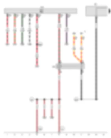
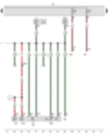
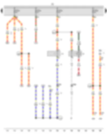
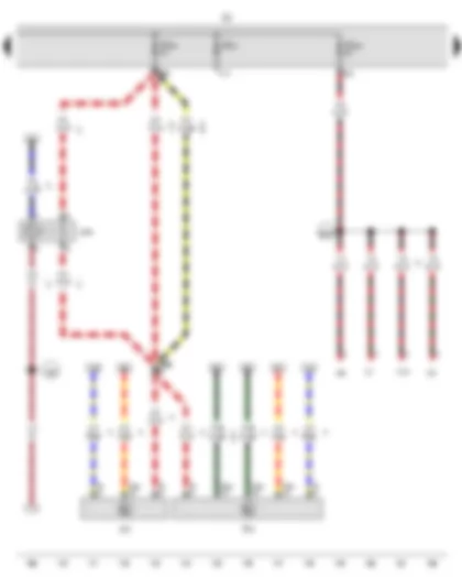
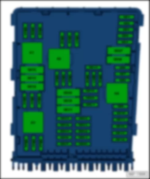
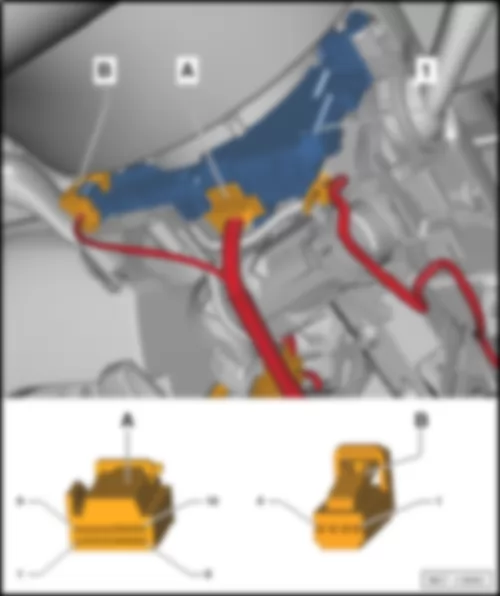
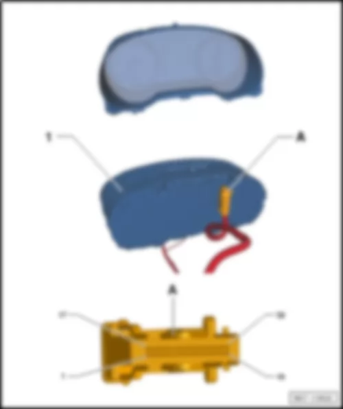
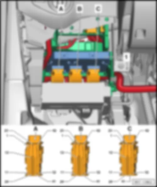
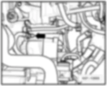
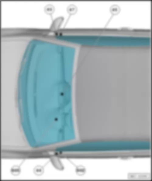
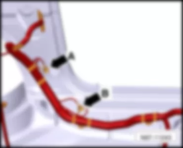
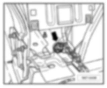
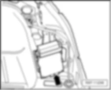
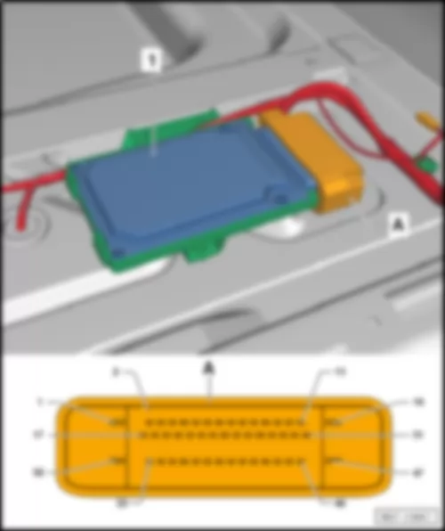
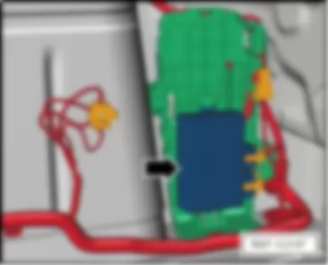
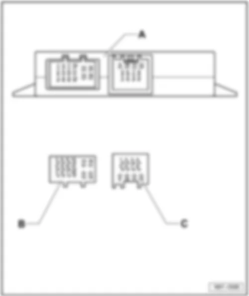
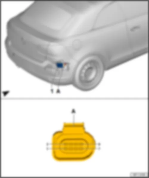
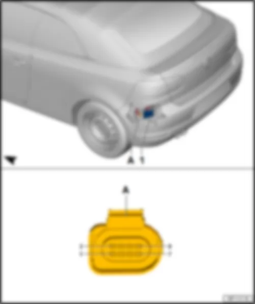
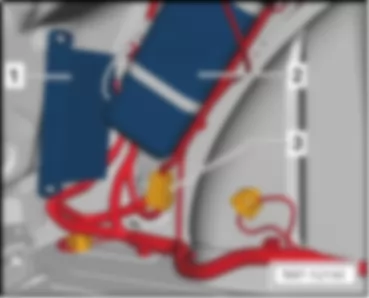
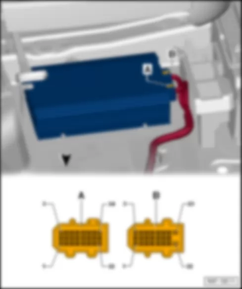
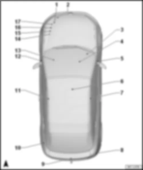
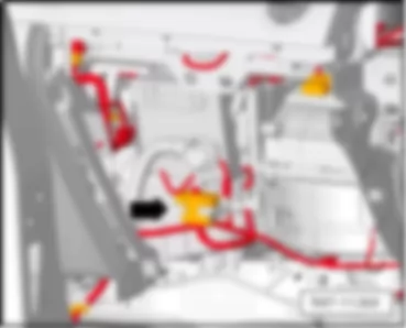
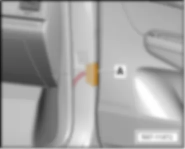
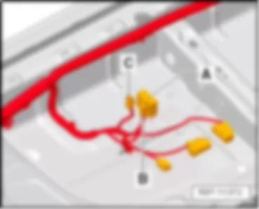
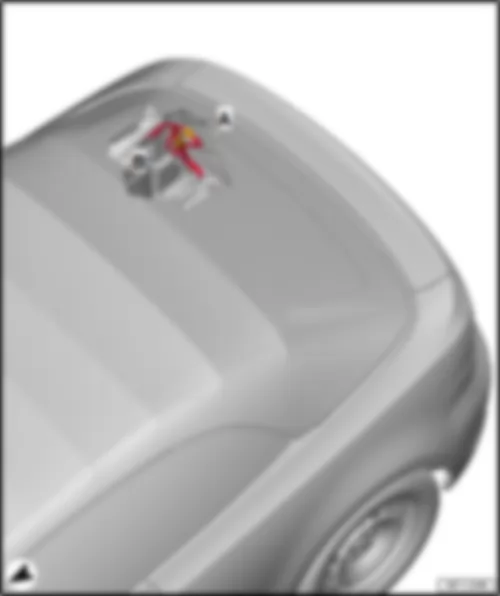
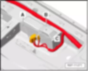
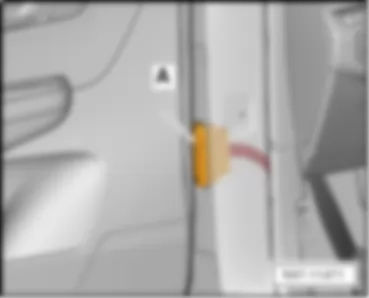
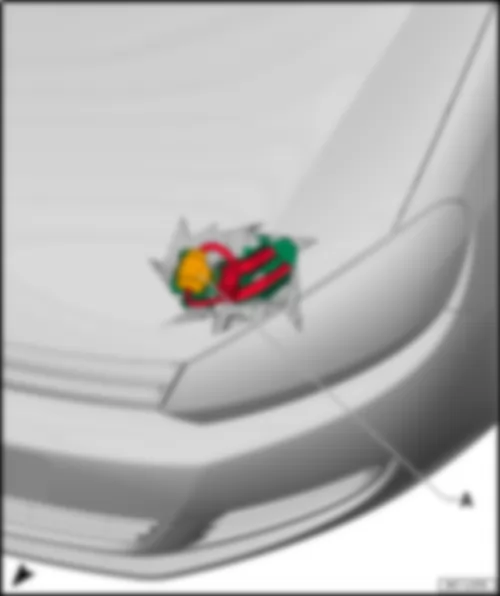
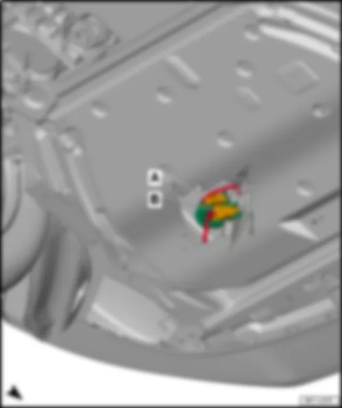
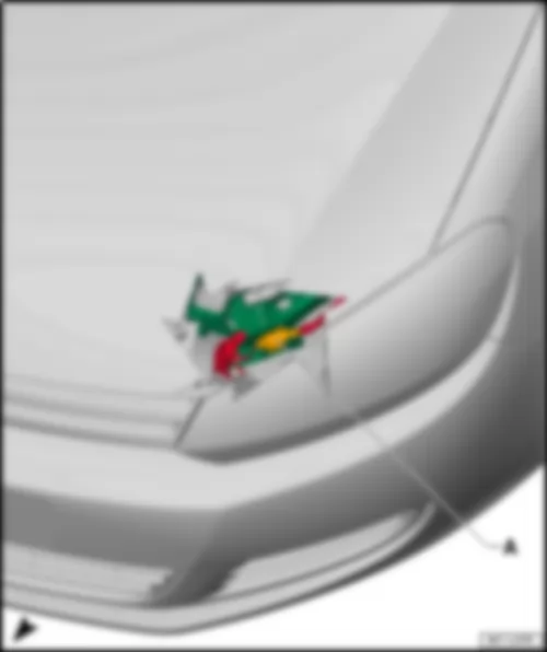
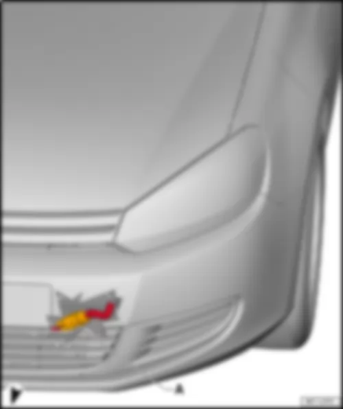
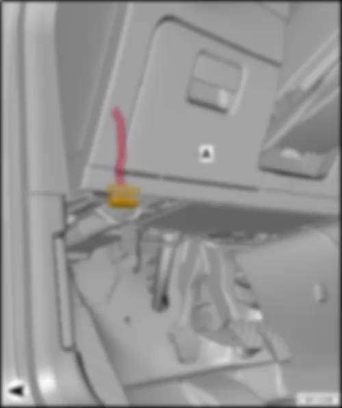
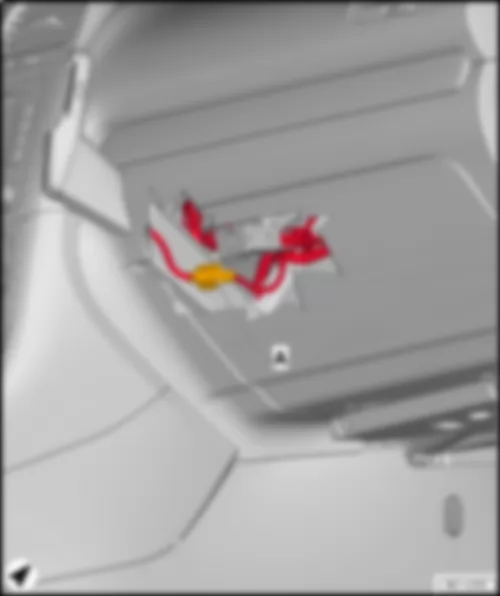
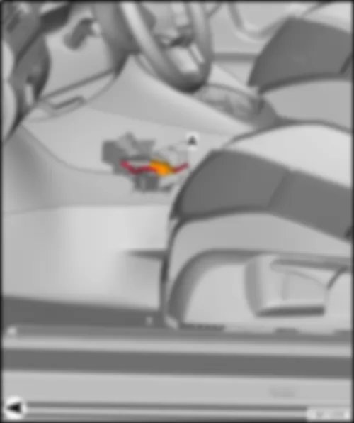
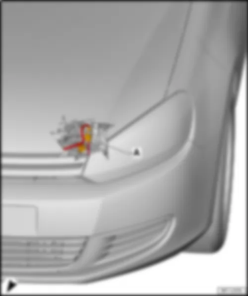
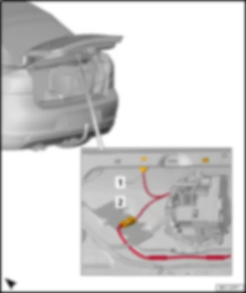
Wiring Diagram VW GOLF CABRIOLET 2014 - Terminal 15 voltage supply relay - Onboard supply control unit - Fuse holder C
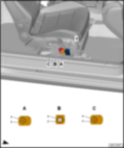
| J329 | Terminal 15 voltage supply relay |
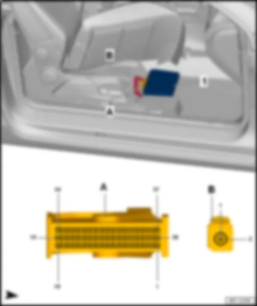
| J519 | Onboard supply control unit |
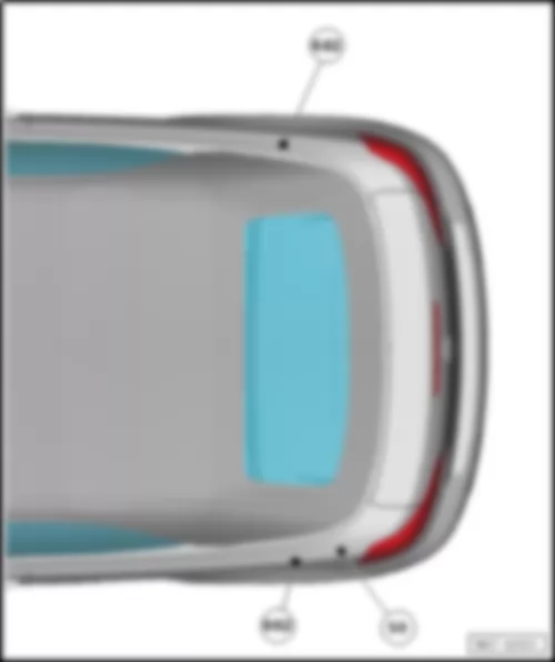
| SB6 | Fuse 6 on fuse holder B |
| SB7 | Fuse 7 on fuse holder B |
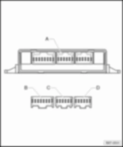
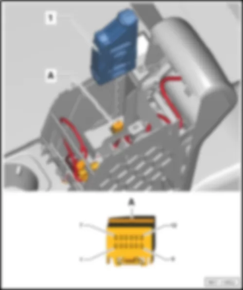
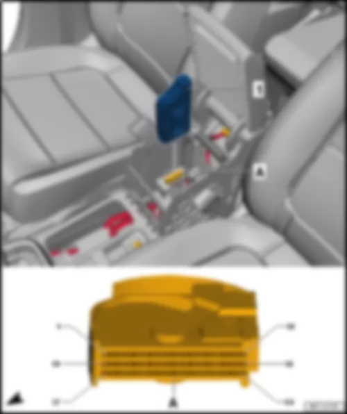
| SC | Fuse holder C |
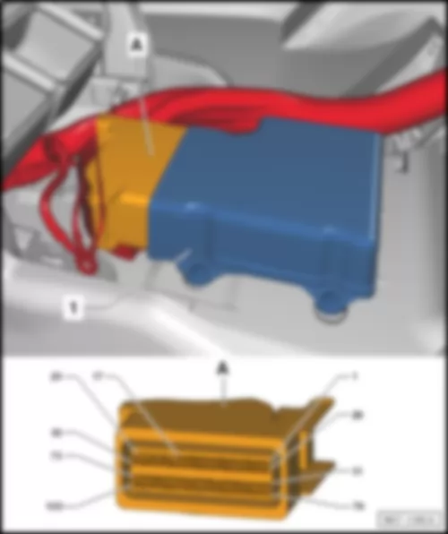
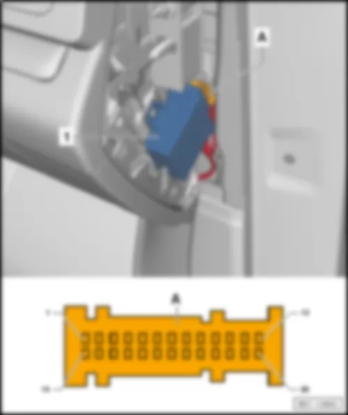
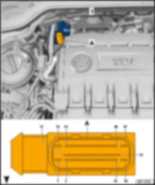
| T40 | 40-pin connector |
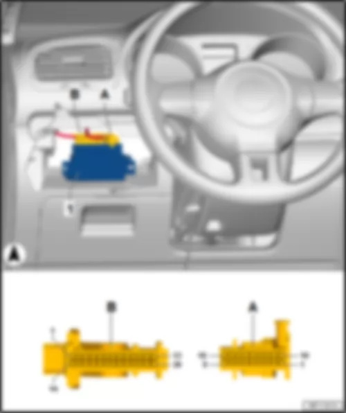
| T52b | 52-pin connector |
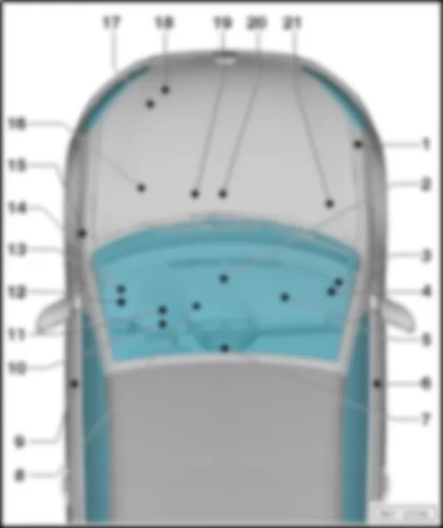
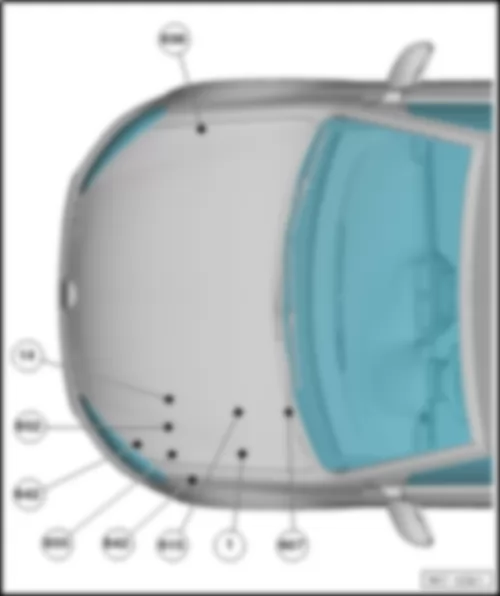
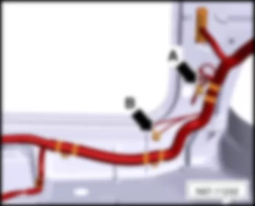
| 44 | Earth point, lower part of left A-pillar |
| 367 | Earth connection 2, in main wiring harness |
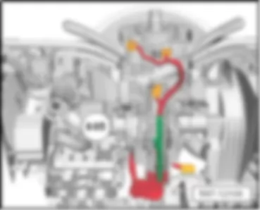
| 605 | Earth point, on top end of steering column |
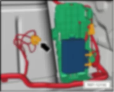
| B163 | Positive connection 1 (15), in interior wiring harness |
| B489 | Connection 25, in main wiring harness |
| * | E-box high |
| *2 | E-box low |
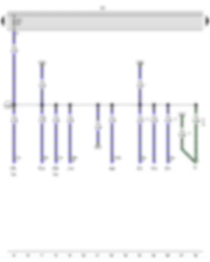
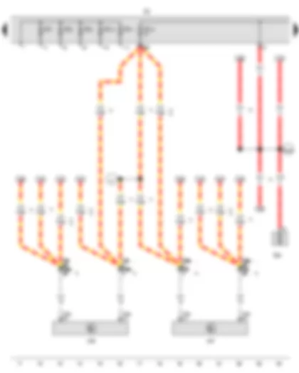
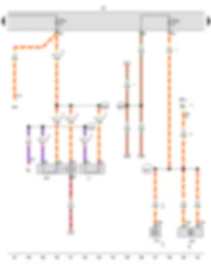
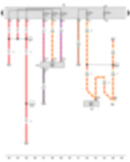
Wiring Diagram VW GOLF CABRIOLET 2014 - Fuse holder C - Fuse 1 on fuse holder C
| E102 | Headlight range control regulator |
| F4 | Reversing light switch |
| G70 | Air mass meter |
| J745 | Control unit for cornering light and headlight range control |
| J869 | Control unit for structure-borne sound |
| MX1 | Front left headlight |
| MX2 | Front right headlight |
| N79 | Heater element for crankcase breather |
| SC | Fuse holder C |
| SC1 | Fuse 1 on fuse holder C |
| T3aj | 3-pin connector |
| T5d | 5-pin connector |
| T8e | 8-pin connector |
| T10i | 10-pin connector |
| T10j | 10-pin connector |
| T12ab | 12-pin connector |
| T26h | 26-pin connector |
| V48 | Left headlight range control motor |
| V49 | Right headlight range control motor |
| A192 | Positive connection 3 (15a) in dash panel wiring harness |
| * | Only models with no Climatronic |
| *2 | see applicable current flow diagram for engine |
| *3 | Not for models with dual clutch gearbox |
| *4 | Only models with 2.0l engine |
| *5 | Only models with petrol engine |
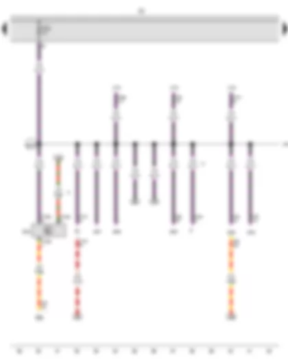
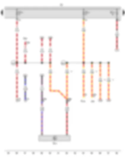
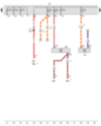
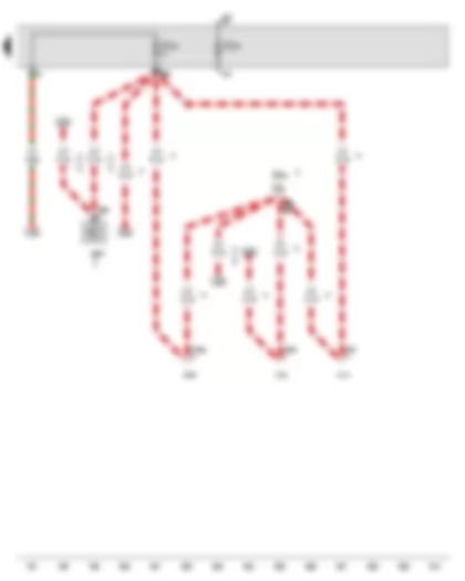
Wiring Diagram VW GOLF CABRIOLET 2014 - Fuse holder C - Fuse 2 on fuse holder C
| E1 | Light switch |
| F | Brake light switch |
| J104 | ABS control unit |
| J285 | Control unit in dash panel insert |
| J532 | Voltage stabiliser |
| J533 | Data bus diagnostic interface |
| J623 | Engine control unit |
| J743 | Mechatronic unit for dual clutch gearbox |
| J906 | Starter relay 1 |
| J907 | Starter relay 2 |
| SB8 | Fuse 8 on fuse holder B |
| SC | Fuse holder C |
| SC2 | Fuse 2 on fuse holder C |
| T4bc | 4-pin connector |
| T10h | 10-pin connector |
| T12ac | 12-pin connector |
| T20 | 20-pin connector |
| T20e | 20-pin connector |
| T25 | 25-pin connector |
| T32 | 32-pin connector |
| T40 | 40-pin connector |
| T47c | 47-pin connector |
| T94 | 94-pin connector |
| B278 | Positive connection 2 (15a) in main wiring harness |
| * | E-box low |
| *2 | Up to October 2011 |
| *3 | Only models with start/stop system |
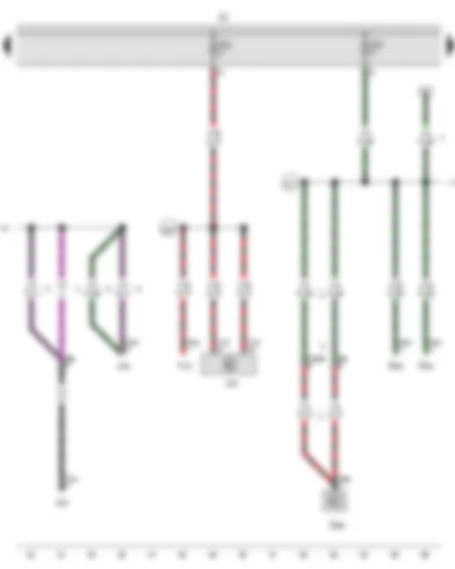
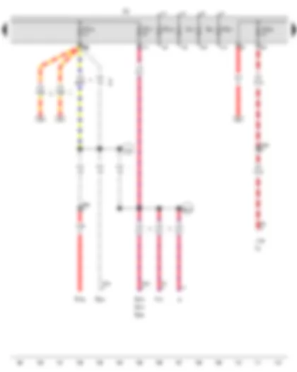
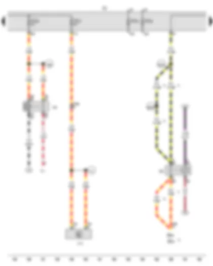
Wiring Diagram VW GOLF CABRIOLET 2014 - Fuse holder C - Fuse 3 on fuse holder C - Fuse 4 on fuse holder C
| E256 | Button for TCS and electronic stabilisation program |
| E492 | Tyre Pressure Loss Indicator button |
| G266 | Oil level and oil temperature sender |
| J234 | Airbag control unit |
| J500 | Power steering control unit |
| J538 | Fuel pump control unit |
| K145 | Front passenger side airbag deactivated warning lamp |
| SC | Fuse holder C |
| SC3 | Fuse 3 on fuse holder C |
| SC4 | Fuse 4 on fuse holder C |
| T2be | 2-pin connector |
| T3bq | 3-pin connector |
| T3by | 3-pin connector, black |
| T6ad | 6-pin connector |
| T6ak | 6-pin connector |
| T6z | 6-pin connector, near left headlight |
| T10am | 10-pin connector, black |
| T10n | 10-pin connector |
| T100 | 100-pin connector |
| A200 | Positive connection 5 (15a) in dash panel wiring harness |
| A217 | Positive connection 8 (15a) in dash panel wiring harness |
| B278 | Positive connection 2 (15a) in main wiring harness |
| * | Only models with diesel engine |
| *2 | From May 2015 |
| *3 | Not for models with dual clutch gearbox |
| *4 | From May 2012 |
| *5 | Up to April 2012 |
| *6 | see applicable current flow diagram for engine |
Wiring Diagram VW GOLF CABRIOLET 2014 - Blind spot monitor control unit - Blind Spot Monitor control unit 2 - Fuse holder C - Fuse 5 on fuse holder C - Fuse 6 on fuse holder C
| E693 | Start/Stop operation button |
| G65 | High-pressure sender |
| G238 | Air quality sensor |
| J446 | Parking aid control unit |
| J791 | Park assist steering control unit |
| J844 | Main beam assist control unit |
| J1086 | Blind spot monitor control unit |
| J1087 | Blind Spot Monitor control unit 2 |
| K259 | Start/Stop operation warning lamp |
| MX1 | Front left headlight |
| MX2 | Front right headlight |
| SC | Fuse holder C |
| SC5 | Fuse 5 on fuse holder C |
| SC6 | Fuse 6 on fuse holder C |
| T3as | 3-pin connector, grey |
| T3c | 3-pin connector |
| T6ax | 6-pin connector |
| T8ak | 8-pin connector |
| T8ao | 8-pin connector, black |
| T8ap | 8-pin connector, black |
| T10am | 10-pin connector, black |
| T14e | 14-pin connector |
| T14f | 14-pin connector |
| T16m | 16-pin connector |
| T26k | 26-pin connector, black |
| Y7 | Automatic anti-dazzle interior mirror |
| A217 | Positive connection 8 (15a) in dash panel wiring harness |
| X171 | Connection (15), rear bumper wiring harness |
| * | From November 2014 |
| *2 | Up to October 2014 |
| *3 | Only models with no air conditioning system |
| *4 | Only models with seat heating |
Wiring Diagram VW GOLF CABRIOLET 2014 - Fuse holder C - Fuse 7 on fuse holder C - Fuse 8 on fuse holder C - Fuse 9 on fuse holder C - Fuse 10 on fuse holder C - Fuse 11 on fuse holder C - Fuse 12 on fuse holder C
| J386 | Driver door control unit |
| J387 | Front passenger door control unit |
| SA5 | Fuse 5 in fuse holder A |
| SC | Fuse holder C |
| SC7 | Fuse 7 on fuse holder C |
| SC8 | Fuse 8 on fuse holder C |
| SC9 | Fuse 9 on fuse holder C |
| SC10 | Fuse 10 on fuse holder C |
| SC11 | Fuse 11 on fuse holder C |
| SC12 | Fuse 12 on fuse holder C |
| T20a | 20-pin connector |
| T20b | 20-pin connector |
| T28 | 28-pin connector, in left A-pillar coupling station |
| T28a | 28-pin connector, in right A-pillar coupling station |
| A1 | Positive connection (30a), in dash panel wiring harness |
| B169 | Positive connection 1 (30), in interior wiring harness |
| * | Only left-hand drive models |
| *2 | Only right-hand drive models |
| *3 | Up to April 2012 |
| *4 | From May 2012 |
| *5 | Up to May 2015 |
| *6 | From May 2015 |
Wiring Diagram VW GOLF CABRIOLET 2014 - Fuse holder C - Fuse 13 on fuse holder C - Fuse 14 on fuse holder C - Fuse 15 on fuse holder C
| E313 | Selector lever |
| G397 | Rain and light sensor |
| J255 | Climatronic control unit |
| R149 | Remote control receiver for auxiliary coolant heater |
| SC | Fuse holder C |
| SC13 | Fuse 13 on fuse holder C |
| SC14 | Fuse 14 on fuse holder C |
| SC15 | Fuse 15 on fuse holder C |
| T3ae | 3-pin connector |
| T6j | 6-pin connector |
| T10s | 10-pin connector, under selector lever |
| T16 | 16-pin connector |
| T20c | 20-pin connector |
| A167 | Positive connection 3 (30a) in dash panel wiring harness |
| B315 | Positive connection 1 (30a) in main wiring harness |
| * | From May 2012 |
| *2 | Up to April 2012 |
| *3 | Only models with Climatronic |
| *4 | Only models with no air conditioning system |
| *5 | Only models with Climatic |
Wiring Diagram VW GOLF CABRIOLET 2014 - Fuse 19 in fuse holder - Fuse 20 in fuse holder - Fuse holder C - Fuse 16 on fuse holder C - Fuse 17 on fuse holder C - Fuse 18 on fuse holder C - Fuse 21 on fuse holder C - Fuse 22 on fuse holder C
| E234 | Rear lid handle release button |
| G273 | Interior monitoring sensor |
| G384 | Vehicle inclination sender |
| G578 | Anti-theft alarm sensor |
| H12 | Alarm horn |
| J4 | Dual tone horn relay |
| J126 | Fresh air blower control unit |
| R189 | Reversing camera |
| S19 | Fuse 19 in fuse holder |
| S20 | Fuse 20 in fuse holder |
| SC | Fuse holder C |
| SC16 | Fuse 16 on fuse holder C |
| SC17 | Fuse 17 on fuse holder C |
| SC18 | Fuse 18 on fuse holder C |
| SC21 | Fuse 21 on fuse holder C |
| SC22 | Fuse 22 on fuse holder C |
| T3f | 3-pin connector |
| T4ap | 4-pin connector |
| T4bs | 4-pin connector |
| T4bt | 4-pin connector, in rear lid |
| T6t | 6-pin connector, brown |
| T10k | 10-pin connector |
| V2 | Fresh air blower |
| B318 | Positive connection 4 (30a) in main wiring harness |
| W9 | Positive connection 1 (30), in rear wiring harness |
| * | From May 2012 |
| *2 | Only left-hand drive models |
| *3 | For models with anti-theft alarm system |
| *4 | Up to October 2011 |
| *5 | From November 2011 |
| *6 | Up to April 2012 |
| *7 | Only right-hand drive models |
Wiring Diagram VW GOLF CABRIOLET 2014 - Fuse holder C - Fuse 23 on fuse holder C - Fuse 24 on fuse holder C - Fuse 25 on fuse holder C - Fuse 26 on fuse holder C
| J9 | Heated rear window relay |
| J13 | Fresh air blower relay |
| J388 | Rear left door control unit |
| J389 | Rear right door control unit |
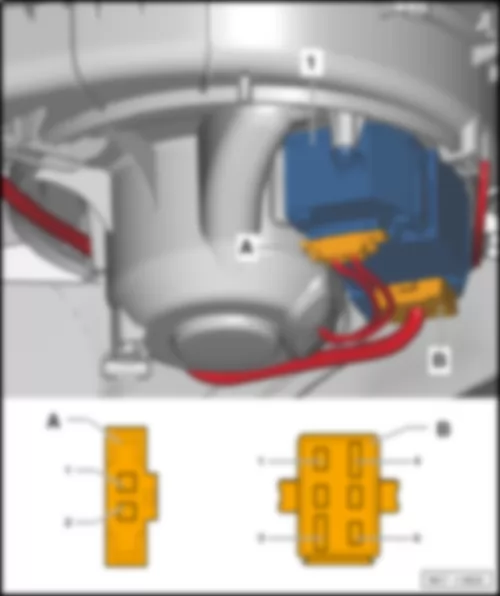
| N24 | Fresh air blower series resistor with overheating fuse |
| SB1 | Fuse 1 on fuse holder B |
| SB3 | Fuse 3 on fuse holder B |
| SC | Fuse holder C |
| SC23 | Fuse 23 on fuse holder C |
| SC24 | Fuse 24 on fuse holder C |
| SC25 | Fuse 25 on fuse holder C |
| SC26 | Fuse 26 on fuse holder C |
| T4f | 4-pin connector |
| T10ak | 10-pin connector, on left in luggage compartment |
| T10k | 10-pin connector |
| T18c | 18-pin connector |
| T18d | 18-pin connector |
| T40 | 40-pin connector |
| Z1 | Heated rear window |
| A168 | Positive connection 4 (30a) in dash panel wiring harness |
| B170 | Positive connection 2 (30), in interior wiring harness |
| L78 | Connection 1, in fresh air blower wiring harness |
| S25 | Positive connection (30a), in central locking wiring harness |
| * | E-box high |
| *2 | E-box low |
| *3 | From May 2012 |
| *4 | Only left-hand drive models |
| *5 | Up to April 2012 |
| *6 | Only models with no Climatronic |
| *7 | Only models with Climatic |
| *8 | Only models with no air conditioning system |
| *9 | Only right-hand drive models |
Wiring Diagram VW GOLF CABRIOLET 2014 - Fuse holder C - Fuse 27 on fuse holder C - Fuse 28 on fuse holder C
| G6 | Fuel system pressurisation pump |
| J17 | Fuel pump relay |
| J503 | Control unit with display for radio and navigation |
| J538 | Fuel pump control unit |
| J643 | Fuel supply relay |
| J794 | Control unit 1 for information electronics |
| R | Radio |
| SB8 | Fuse 8 on fuse holder B |
| SB19 | Fuse 19 on fuse holder B |
| SC | Fuse holder C |
| SC27 | Fuse 27 on fuse holder C |
| SC28 | Fuse 28 on fuse holder C |
| T5b | 5-pin connector |
| T8as | 8-pin connector, black |
| T10n | 10-pin connector |
| T16b | 16-pin connector |
| T40 | 40-pin connector |
| A193 | Connection (87a), in dash panel wiring harness |
| B156 | Positive connection (30a), in interior wiring harness |
| B224 | Connection 1 (radio), in interior wiring harness |
| B320 | Positive connection 6 (30a) in main wiring harness |
| * | E-box high |
| *2 | E-box low |
| *3 | Only models with radio MIB-G Entry |
| *4 | From May 2015 |
| *5 | From May 2012 |
| *6 | Only models with no start/stop system |
| *7 | Only models with start/stop system |
Wiring Diagram VW GOLF CABRIOLET 2014 - Fuse holder C - Fuse 29 on fuse holder C - Fuse 30 on fuse holder C - Fuse 31 on fuse holder C - Fuse 32 on fuse holder C - Fuse 33 on fuse holder C - Fuse 34 on fuse holder C - Fuse 35 on fuse holder C
| J250 | Electronically controlled damping control unit |
| J256 | Convertible roof actuation control unit |
| SB28 | Fuse 28 on fuse holder B |
| SB29 | Fuse 29 on fuse holder B |
| SC | Fuse holder C |
| SC29 | Fuse 29 on fuse holder C |
| SC30 | Fuse 30 on fuse holder C |
| SC31 | Fuse 31 on fuse holder C |
| SC32 | Fuse 32 on fuse holder C |
| SC33 | Fuse 33 on fuse holder C |
| SC34 | Fuse 34 on fuse holder C |
| SC35 | Fuse 35 on fuse holder C |
| SB53 | Fuse 53 on fuse holder B |
| SB54 | Fuse 54 on fuse holder B |
| T10aj | 10-pin connector |
| T40 | 40-pin connector |
| T47d | 47-pin connector |
| B111 | Positive connection 1 (30a), in interior wiring harness |
| * | E-box high |
| *2 | E-box low |
| *3 | From November 2011 |
| *4 | From May 2012 |
| *5 | Only left-hand drive models |
| *6 | Only right-hand drive models |
Wiring Diagram VW GOLF CABRIOLET 2014 - Headlight washer system relay - Fuse holder C - Fuse 36 on fuse holder C - Fuse 37 on fuse holder C - Fuse 38 on fuse holder C - Fuse 39 on fuse holder C
| J39 | Headlight washer system relay |
| J59 | X-contact relief relay |
| J774 | Heated front seats control unit |
| SB30 | Fuse 30 on fuse holder B |
| SC | Fuse holder C |
| SC36 | Fuse 36 on fuse holder C |
| SC37 | Fuse 37 on fuse holder C |
| SC38 | Fuse 38 on fuse holder C |
| SC39 | Fuse 39 on fuse holder C |
| SB52 | Fuse 52 on fuse holder B |
| T8z | 8-pin connector |
| T10a | 10-pin connector, under driver seat |
| T40 | 40-pin connector |
| V11 | Headlight washer system pump |
| A98 | Positive connection 4 (30), in dash panel wiring harness |
| B162 | Connection (75a), in interior wiring harness |
| B349 | Connection 2 (75a), in main wiring harness |
| O1 | Positive connection (30), in seat heating wiring harness |
| * | E-box high |
| *2 | E-box low |
| *3 | Up to April 2013 |
| *4 | Only models with no Climatronic |
| *5 | From May 2013 |
| *6 | Only models with Climatronic |
Wiring Diagram VW GOLF CABRIOLET 2014 - Fuse holder C - Fuse 40 on fuse holder C - Fuse 41 on fuse holder C - Fuse 42 on fuse holder C
| E16 | Heater/heat output switch |
| J29 | Blocking diode |
| J301 | Air conditioning system control unit |
| J485 | Auxiliary heater operation relay |
| SC | Fuse holder C |
| SC40 | Fuse 40 on fuse holder C |
| SC41 | Fuse 41 on fuse holder C |
| SC42 | Fuse 42 on fuse holder C |
| T5 | 5-pin connector |
| T10k | 10-pin connector |
| T20c | 20-pin connector |
| U1 | Cigarette lighter |
| U5 | 12 V socket, on right in luggage compartment |
| U18 | 12 V socket 2, in rear centre console |
| 389 | Earth connection 24, in main wiring harness |
| B348 | Connection 1 (75a), in main wiring harness |
| * | Only models with auxiliary coolant heater |
| *2 | Only models with no Climatronic |
| *3 | Only models with Climatic |
| *4 | Only models with no air conditioning system |
| *5 | Only models with no auxiliary coolant heater |
| *6 | Up to October 2011 |
| *7 | From November 2011 |
| *8 | According to equipment |
| *9 | Only models with seat heating |
Wiring Diagram VW GOLF CABRIOLET 2014 - Fuse holder C - Fuse 43 on fuse holder C - Fuse 44 on fuse holder C - Fuse 45 on fuse holder C - Fuse 46 on fuse holder C - Fuse 47 on fuse holder C
| J345 | Trailer detector control unit, in rear left side panel |
| J527 | Steering column electronics control unit |
| SB6 | Fuse 6 on fuse holder B |
| SC | Fuse holder C |
| SC43 | Fuse 43 on fuse holder C |
| SC44 | Fuse 44 on fuse holder C |
| SC45 | Fuse 45 on fuse holder C |
| SC46 | Fuse 46 on fuse holder C |
| SC47 | Fuse 47 on fuse holder C |
| T12h | 12-pin connector |
| T16r | 16-pin connector |
| T40 | 40-pin connector |
| A32 | Positive connection (30), in dash panel wiring harness |
| B188 | Positive connection 5 (30), in interior wiring harness |
| B504 | Positive connection 8 (30a), in interior wiring harness |
| * | E-box low |
| *2 | From May 2015 |
| *3 | Up to May 2015 |
| *4 | Only models with no start/stop system |
| *5 | Only models with start/stop system |
Wiring Diagram VW GOLF CABRIOLET 2014 - Emergency call module control unit and communication unit - Fuse holder C - Fuse 48 on fuse holder C - Fuse 49 on fuse holder C
| J412 | Mobile telephone operating electronics control unit |
| J794 | Control unit 1 for information electronics |
| J856 | Control unit for navigation system |
| J949 | Emergency call module control unit and communication unit |
| SB9 | Fuse 9 on fuse holder B |
| SB20 | Fuse 20 on fuse holder B |
| SC | Fuse holder C |
| SC48 | Fuse 48 on fuse holder C |
| SC49 | Fuse 49 on fuse holder C |
| T10ko | 10-pin connector |
| T26i | 26-pin connector |
| T40 | 40-pin connector |
| T54 | 54-pin connector |
| T54b | 54-pin connector |
| * | E-box low |
| *2 | E-box high |
| *3 | From May 2014 |
| *4 | Only models with equipment for China |
| *5 | Only models with start/stop system |
| *6 | Only models with no start/stop system |
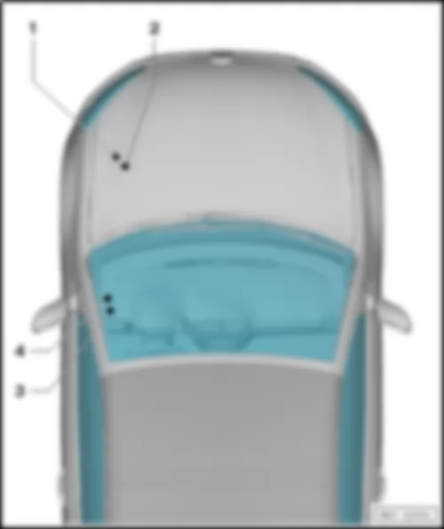
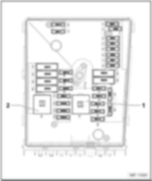
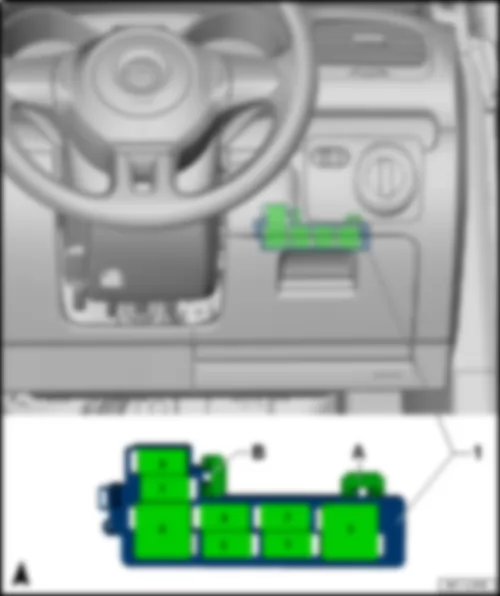
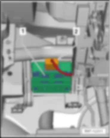
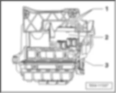
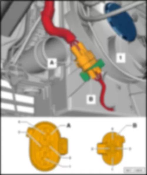
VW GOLF CABRIOLET 2014 Overview of relay carriers
| 1 - | Relay carrier on E-box |
| q | On left in engine compartment |
| q | Relay assignment on E-box low → Chapter |
| q | Relay assignment on E-box high → Chapter |
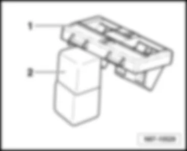
| 2 - | Auxiliary relay carrier under E-box |
| q | On left in engine compartment |
| q | Relay position assignment → Chapter |
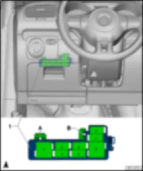
| 3 - | Relay carrier (basic) on top of onboard supply control unit |
| q | Relay assignment for left-hand drive vehicle, to April 2013 → Chapter |
| q | Relay assignment for left-hand drive vehicle, from May 2013 → Chapter |
| q | Relay assignment for right-hand drive vehicle, to April 2013 → Chapter |
| q | Relay assignment for right-hand drive vehicle, from May 2013 → Chapter |
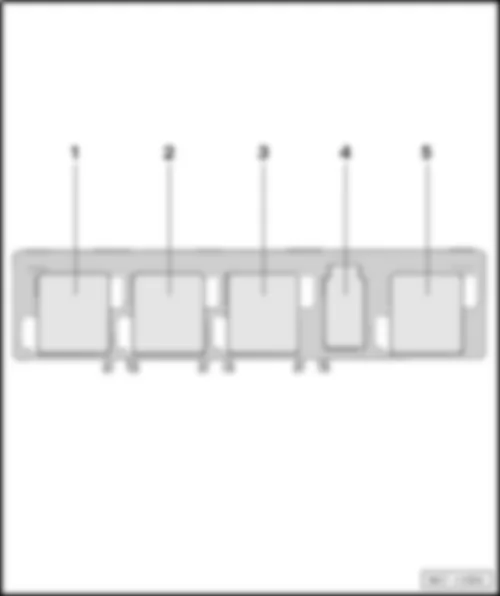
| 4 - | Relay carrier (optional) on bottom of onboard supply control unit |
| q | Relay position assignment → Chapter |
| Relay assignment on E-box low |
| A1 - | Terminal 30 voltage supply relay -J317- (100) |
| - | Motronic current supply relay -J271- (100) |
| A2 - | Secondary air pump relay -J299- (100) |
| - | Connection bridge -TV23- |
| q | Only models with a diesel engine |
| A2 - | Additional coolant pump relay -J496- (100) |
|
| Relay locations on E-box high |
| A1 - | Main relay -J271- (100) |
| A2 - | Additional coolant pump relay -J496- (100) |
| A3 - | Vacant |
| A4 - | Engine component current supply relay -J757- (167) |
|
| Relay position assignment on additional relay carrier under E-box low |
| 1 - | Auxiliary relay carrier, under E-box on left in engine compartment |
| 2 - | Automatic glow period control unit -J179- (457) |
Note
|
| A - | Fuse holder |
| B - | Fuse holder |
| 1 - | Terminal 15 voltage supply relay -J329- (645) |
| 2 / 3 - | X-contact relief relay -J59- (644) |
| 4 - | Dual tone horn relay -J4- (646) |
| 5 - | Headlight washer system relay -J39- (646) |
| 6 - | Heated rear window relay -J9- (645) |
| 7 / 8 - | Terminal 50 voltage supply relay -J682- (645) 1 |
| q | 1 Models with no start/stop system |
| - | Starter relay 1 -J906- (645) 2 |
| q | 2 Models with start/stop system |
Note
|
| A - | Fuse holder |
| B - | Fuse holder |
| 1 - | Terminal 15 voltage supply relay -J329- (645) |
| 2 / 3 - | Terminal 50 voltage supply relay -J682- (645) 1 |
| q | 1 Models with no start/stop system |
| - | Starter relay 1 -J906- (645) 2 |
| q | 2 Models with start/stop system |
| 4 - | Dual tone horn relay -J4- (646) |
| 5 - | Headlight washer system relay -J39- (646) |
| 6 - | Heated rear window relay -J9- (645) |
| 7 / 8 - | X-contact relief relay -J59- (644) 3 / (645) 4 |
| q | 3 Models with no Climatronic |
| q | 4 Models with Climatronic |
|
| Relay carrier (optional) on bottom of onboard supply control unit |
| 1 - | Starter relay 2 -J907- (507) 2 |
| q | 2 Models with start/stop system |
| 2 - | Fuel pump relay -J17- (646) |
| q | Slot 2, top |
| - | Continued coolant circulation relay -J151- (646) |
| q | Slot 2, top |
| - | Fuel supply relay -J643- (646) |
| q | Slot 2, bottom |
| 3 - | Low heat output relay -J359- (645) |
| q | Slot 3 |
| - | Auxiliary heater operation relay -J485- (645) |
| q | Slot 3 |
| 4 - | Electric fuel pump 2 relay -J49- (646) |
| q | Slot 4 |
| - | Heater element relay -J925- (646) |
| q | Slot 4 |
| 5 - | Fresh air blower relay -J13- (646) |
| q | Slot 5, top |
| - | High heat output relay -J360- (644) |
| q | Slot 5 |
|

 Deutsch
 English
 English
 Español
 Français
 Nederlands

