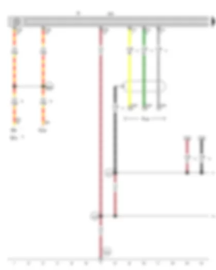
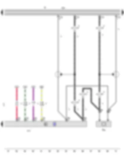
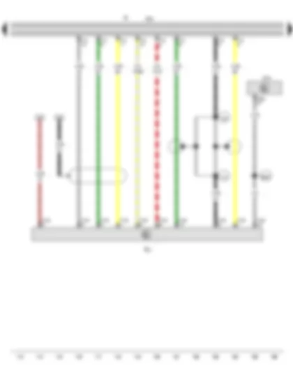
Wiring Diagram VW GOLF CABRIOLET 2014 - Control unit with display for radio and navigation - Radio - Connection for external audio sources
| J503 | Control unit with display for radio and navigation |
| R | Radio |
| R199 | Connection for external audio sources |
| SB8 | Fuse 8 on fuse holder B |
| SB19 | Fuse 19 on fuse holder B |
| SC28 | Fuse 28 on fuse holder C |
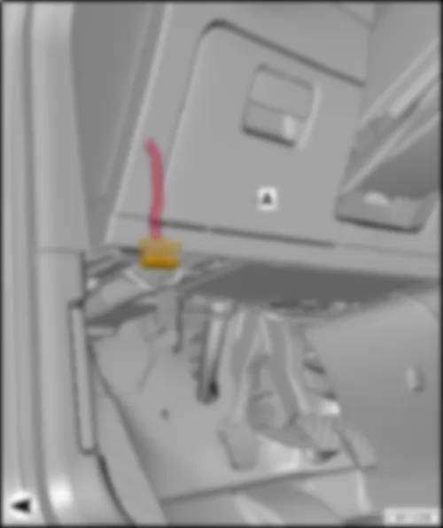
| T4cm | 4-pin connector, in glove compartment |
| T12 | 12-pin connector |
| T16b | 16-pin connector |
| T40 | 40-pin connector |
| 370 | Earth connection 5, in main wiring harness |
| 371 | Earth connection 6, in main wiring harness |
| 610 | Earth point (audio), front below centre console |
| B224 | Connection 1 (radio), in interior wiring harness |
| * | E-box low |
| *2 | E-box high |
| *3 | Only models with CD changer |
| *4 | Only models with connection for external audio sources with no electrical interface |
| *5 | Only models with no start/stop system |
| *6 | Only models with start/stop system |
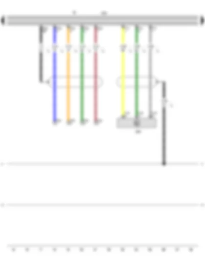
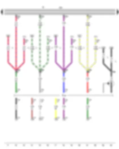
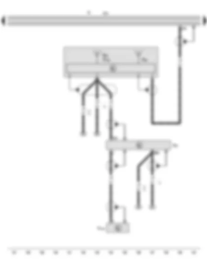
Wiring Diagram VW GOLF CABRIOLET 2014 - Control unit with display for radio and navigation - Multimedia system control unit - Radio
| J503 | Control unit with display for radio and navigation |
| J650 | Multimedia system control unit, under centre armrest, front |
| R | Radio |
| T4cw | 4-pin connector |
| T4cx | 4-pin connector, in front centre armrest, USB connection |
| T12 | 12-pin connector |
| T12t | 12-pin connector |
| 370 | Earth connection 5, in main wiring harness |
| 371 | Earth connection 6, in main wiring harness |
| * | Only models with connection for external multi-media devices with electrical interface |
| *2 | Only models with radio navigation system RNS 315 |
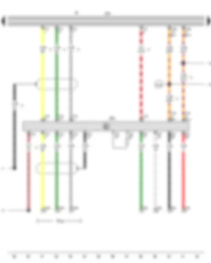
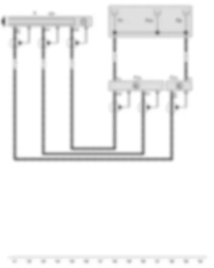
Wiring Diagram VW GOLF CABRIOLET 2014 - Control unit with display for radio and navigation - Multimedia system control unit - Radio - Connection for external audio sources
| J503 | Control unit with display for radio and navigation |
| J650 | Multimedia system control unit |
| R | Radio |
| R199 | Connection for external audio sources |
| T4bj | 4-pin connector, in front centre armrest, USB connection |
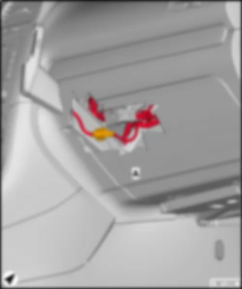
| T4cm | 4-pin connector, in rear centre console |
| T12 | 12-pin connector |
| T12t | 12-pin connector |
| T16b | 16-pin connector |
| T30 | 30-pin connector |
| 370 | Earth connection 5, in main wiring harness |
| 371 | Earth connection 6, in main wiring harness |
| A178 | Connection (infotainment CAN bus, high), in dash panel wiring harness |
| A179 | Connection (infotainment CAN bus, low), in dash panel wiring harness |
| * | Only models with multimedia socket for external audio source |
| *2 | Only models with connection for external multi-media devices with electrical interface |
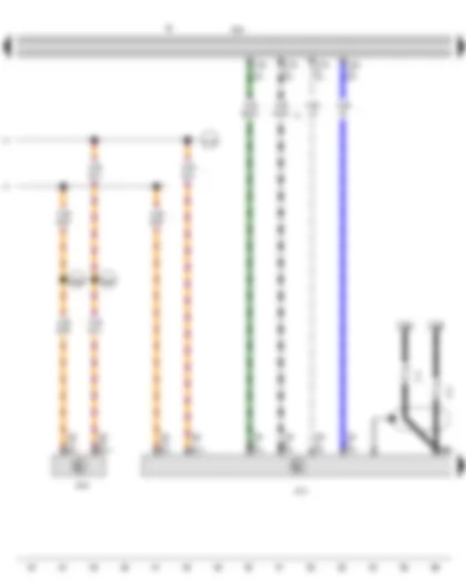
Wiring Diagram VW GOLF CABRIOLET 2014 - Mobile telephone operating electronics control unit - Control unit with display for radio and navigation - Data bus diagnostic interface - Radio
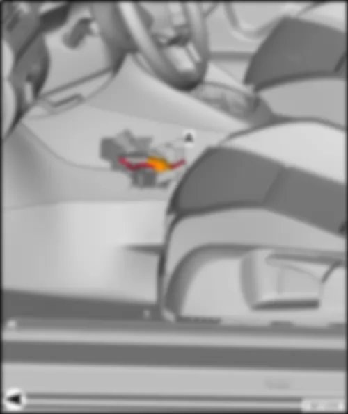
| J412 | Mobile telephone operating electronics control unit, under seat on front right |
| J503 | Control unit with display for radio and navigation |
| J533 | Data bus diagnostic interface |
| R | Radio |
| T12g | 12-pin connector |
| T20 | 20-pin connector |
| T54 | 54-pin connector |
| A178 | Connection (infotainment CAN bus, high), in dash panel wiring harness |
| A179 | Connection (infotainment CAN bus, low), in dash panel wiring harness |
| A225 | Connection 2 (infotainment CAN bus, high) in dash panel wiring harness |
| A226 | Connection 2 (infotainment CAN bus, low) in dash panel wiring harness |
| * | Only models with mobile telephone/telephone |
| *2 | According to equipment |
| *3 | Only models with charger unit for telephone and mobile telephone operating electronics control unit |
| *4 | Only models with no auxiliary coolant heater |
| *5 | Only models with auxiliary coolant heater |
Wiring Diagram VW GOLF CABRIOLET 2014 - Mobile telephone operating electronics control unit - Control unit with display for radio and navigation - Radio - Telephone microphone
| J412 | Mobile telephone operating electronics control unit, under seat on front right |
| J503 | Control unit with display for radio and navigation |
| R | Radio |
| R38 | Telephone microphone |
| T2f | 2-pin connector, near front interior light |
| T12g | 12-pin connector |
| T54 | 54-pin connector |
| * | Only models with mobile telephone/telephone |
| *2 | Only models with charger unit for telephone and mobile telephone operating electronics control unit |
| *3 | Only models with voice control |
| *4 | Only models with no telephone/ preparation for mobile telephone |
| *5 | From May 2013 |
Wiring Diagram VW GOLF CABRIOLET 2014 - Control unit with display for radio and navigation - Radio - Telephone bracket
| J412 | Mobile telephone operating electronics control unit, under centre armrest, front |
| J503 | Control unit with display for radio and navigation |
| R | Radio |
| R126 | Telephone bracket |
| T2ce | 2-pin connector, behind glove compartment |
| T10f | 10-pin connector, behind glove compartment |
| T16t | 16-pin connector |
| T26d | 26-pin connector |
| T54b | 54-pin connector |
| * | Only models with charger unit for telephone |
| *2 | Only models with charger unit for telephone and mobile telephone operating electronics control unit |
| *3 | Only models with no auxiliary coolant heater |
| *4 | Only models with auxiliary coolant heater |
| *5 | According to equipment |
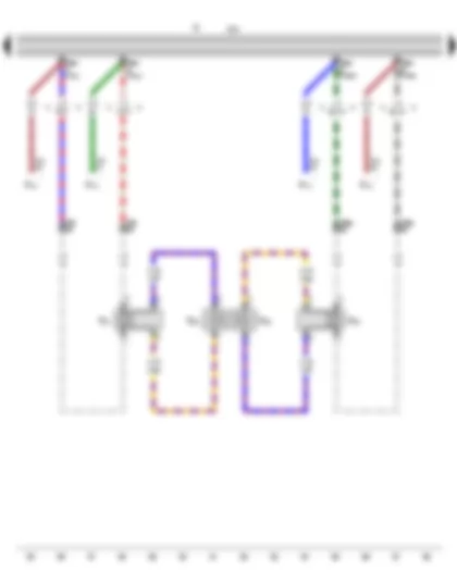
Wiring Diagram VW GOLF CABRIOLET 2014 - Control unit with display for radio and navigation - Radio - Amplifier - Front left treble loudspeaker - Front left bass loudspeaker - Front right treble loudspeaker - Front right bass loudspeaker
| J503 | Control unit with display for radio and navigation |
| R | Radio |
| R12 | Amplifier |
| R20 | Front left treble loudspeaker |
| R21 | Front left bass loudspeaker |
| R22 | Front right treble loudspeaker |
| R23 | Front right bass loudspeaker |
| T8an | 8-pin connector |
| T23 | 23-pin connector |
| T24 | 24-pin connector |
| T28 | 28-pin connector, in left A-pillar coupling station |
| T28a | 28-pin connector, in right A-pillar coupling station |
| * | see applicable current flow diagram for sound system |
| *2 | Only models with no sound system |
| *3 | Only models with sound system |
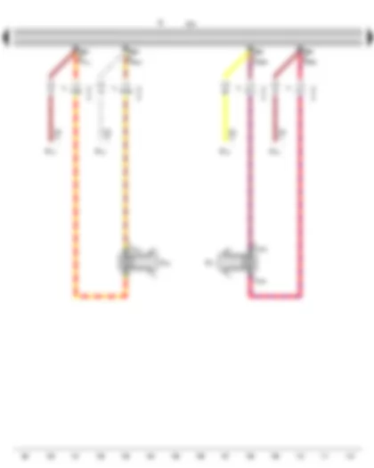
Wiring Diagram VW GOLF CABRIOLET 2014 - Control unit with display for radio and navigation - Radio - Amplifier - Rear left bass loudspeaker - Rear right bass loudspeaker
| J503 | Control unit with display for radio and navigation |
| R | Radio |
| R12 | Amplifier |
| R15 | Rear left bass loudspeaker |
| R17 | Rear right bass loudspeaker |
| T8an | 8-pin connector |
| T24 | 24-pin connector |
| * | see applicable current flow diagram for sound system |
| *2 | Only models with rear loudspeaker |
| *3 | Only models with passive loudspeakers |
| *4 | Only models with no sound system |
| *5 | Only models with sound system |
Wiring Diagram VW GOLF CABRIOLET 2014 - Control unit with display for radio and navigation - Radio - CD changer
| J503 | Control unit with display for radio and navigation |
| J519 | Onboard supply control unit |
| R | Radio |
| R41 | CD changer |
| T12 | 12-pin connector |
| T12d | 12-pin connector |
| T52b | 52-pin connector |
| B340 | Connection 1 (58d), in main wiring harness |
| V14 | Connection (screening), in CD changer wiring harness |
| V45 | Connection 2 (screening), in CD changer wiring harness |
| * | Only models with CD changer |
Wiring Diagram VW GOLF CABRIOLET 2014 - Control unit with display for radio and navigation - Radio - GPS aerial - Telephone aerial - Aerial filter - Remote control receiver for auxiliary coolant heater - Auxiliary heater aerial
| J503 | Control unit with display for radio and navigation |
| R | Radio |
| R50 | GPS aerial |
| R65 | Telephone aerial |
| R87 | Aerial filter |
| R149 | Remote control receiver for auxiliary coolant heater |
| R182 | Auxiliary heater aerial |
| * | Only models with charger unit for telephone |
| *2 | Only models with no auxiliary coolant heater |
| *3 | Only models with charger unit for telephone and mobile telephone operating electronics control unit |
| *4 | Only models with auxiliary coolant heater |
Wiring Diagram VW GOLF CABRIOLET 2014 - Control unit with display for radio and navigation - Radio - Aerial - Radio aerial 2 - Left aerial module - Right aerial module
| J503 | Control unit with display for radio and navigation |
| R | Radio |
| R11 | Aerial |
| R93 | Radio aerial 2 |
| R108 | Left aerial module, near left roof member |
| R109 | Right aerial module, near right roof member |
| R183 | Digital radio aerial |
| T1g | Single connector |
| T1h | Single connector |
| * | Only models with digital radio |
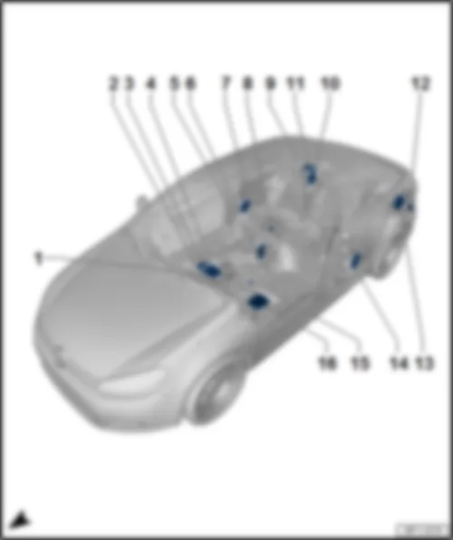
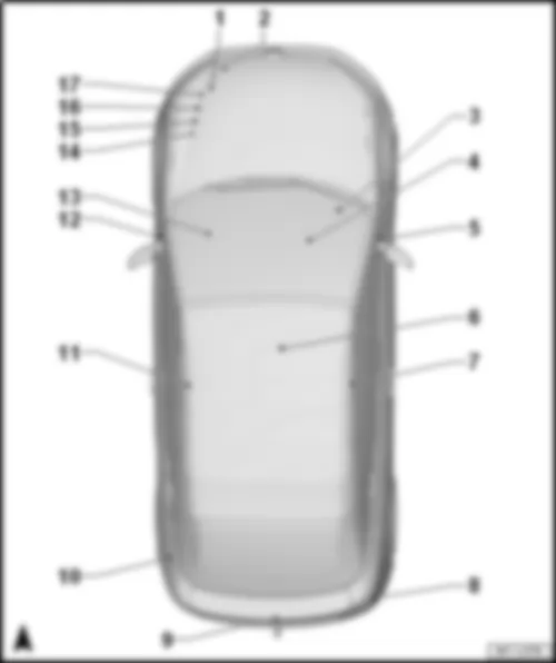
VW GOLF CABRIOLET 2014 Overview of control units
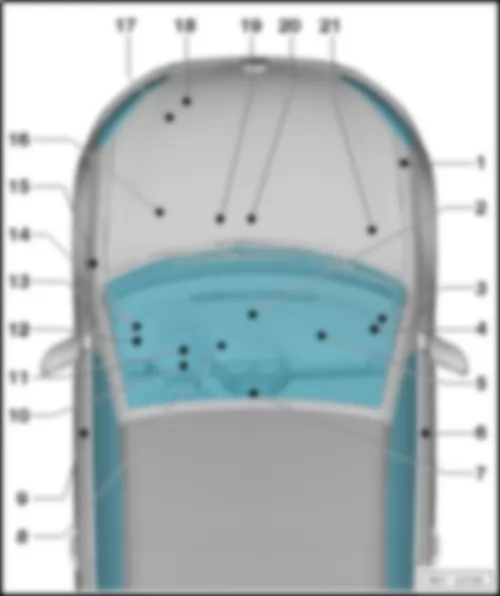
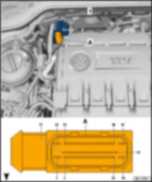
| 1 - | Emergency call module control unit and communication unit -J949- |
| q | Fitting location → Chapter |
| q | Connector assignment → Chapter |
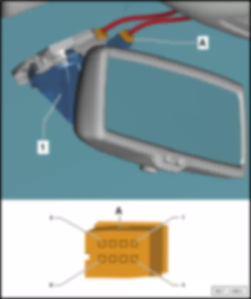
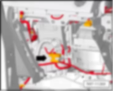
| 2 - | Remote control receiver for auxiliary coolant heater -R149- |
| q | Fitting location → Chapter |
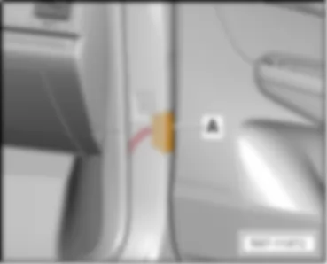
| 3 - | Aerial filter -R87- |
| q | Fitting location → Chapter |
| 4 - | Mobile telephone operating electronics control unit -J412- |
| q | Only models with no multimedia socket MEDIA-IN |
| q | See point 5 for model with multimedia socket MEDIA-IN |
| q | Fitting location → Chapter |
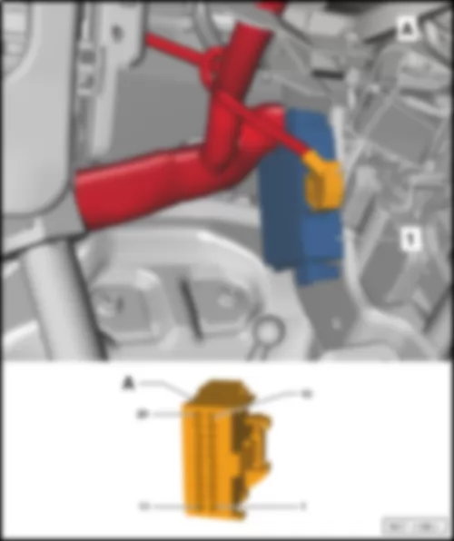
| 5 - | Multimedia system control unit -J650- |
| q | Fitting location → Chapter |
| 6 - | Mobile telephone operating electronics control unit -J412- |
| q | Only models with multimedia socket MEDIA-IN |
| q | Fitting location and / assignment → Chapter |
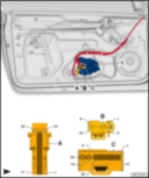
| 7 - | Rear right window regulator motor -V27- |
| q | Connector assignment → Chapter |
| 8 - | Fuel pump control unit -J538- |
| q | Fitting location → Chapter |
| 9 - | Electronically controlled damping control unit -J250- |
| q | Fitting location → Chapter |
| q | Connector assignment → Chapter |
| 10 - | Trailer detector control unit -J345- |
| q | Fitting location → Chapter |
| q | Connector assignment → Chapter |
| 11 - | Blind spot monitor control unit -J1086- |
| q | Fitting location → Chapter |
| q | Connector assignment → Chapter |
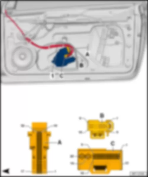
| 12 - | Blind spot monitor control unit 2 -J1087- |
| q | Fitting location → Chapter |
| q | Connector assignment → Chapter |
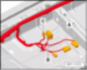
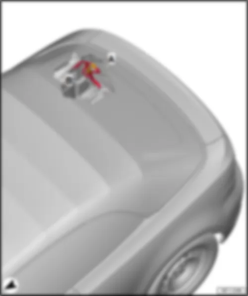
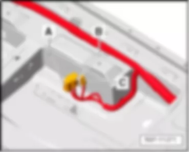
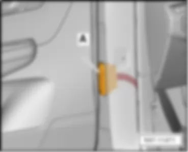
| 13 - | Convertible roof actuation control unit -J256- |
| q | Fitting location → Chapter |
| 14 - | Rear left window regulator motor -V26- |
| q | Connector assignment → Chapter |
| 15 - | Heated front seats control unit -J774- |
| q | Fitting location → Chapter |
| q | Connector assignment → Chapter |
| 16 - | Amplifier -R12- |
| q | Fitting location and / assignment → Chapter |
|
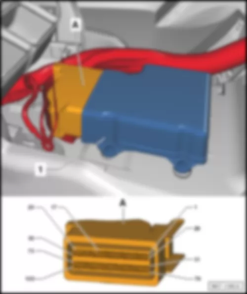
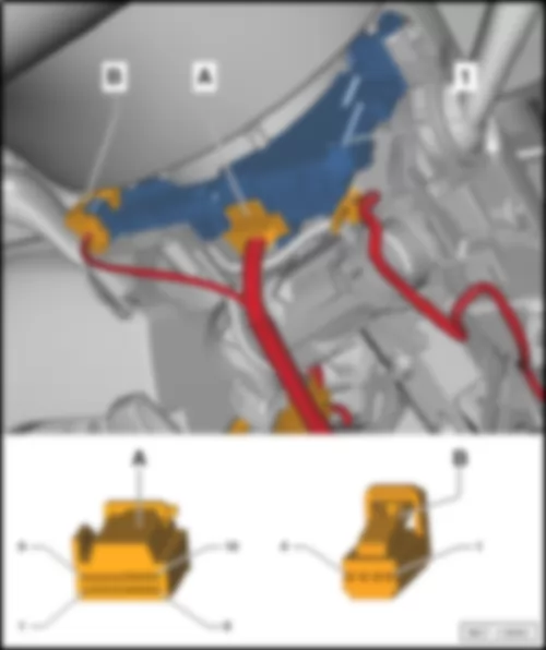
| 1 - | Emergency call module control unit and communication unit -J949- |
| A - | 26-pin connector -T26i, schwarz- |
| B - | Aerial connection |
|
| -T26i- (A) | Designation |
| 1 | Terminal 30 |
| 2 | A179 Connection (infotainment CAN bus, low), in dash panel wiring harness |
| 3 | |
| 4 | Telephone microphone -R38- (+) |
| 5 | Control unit with display for radio and navigation -J503- (microphone +) |
| 6 | Telematics button module -E734- |
| 7 | Telematics button module -E734- |
| 8 | |
| 9 | |
| 10 | Control unit with display for radio and navigation -J503- (out +) |
| 11 | Control unit with display for radio and navigation -J503- (out -) |
| 12 | |
| 13 | |
| 14 | A178 Connection (infotainment CAN bus, high), in dash panel wiring harness |
| 15 | |
| 16 | |
| 17 | Telephone microphone -R38- (shielding) |
| 18 | Control unit with display for radio and navigation -J503- (shielding) |
| 19 | Telematics button module -E734- |
| 20 | Telematics button module -E734- |
| 21 | |
| 22 | |
| 23 | |
| 24 | |
| 25 | |
| 26 | Terminal 31 |
|
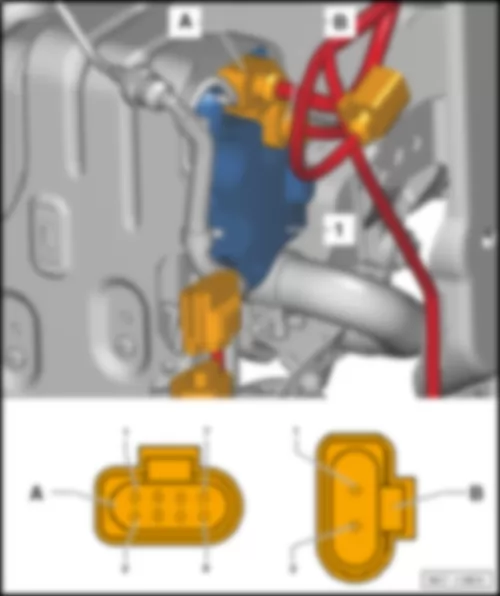
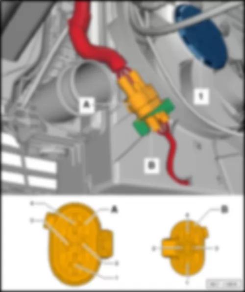
| 1 - | Remote control receiver for auxiliary coolant heater -R149- |
| A - | Connector -Antenne- |
| B - | 6-pin connector -T6j- |
|
| 1 - | Aerial filter -R87- |
| A - | Connector -Antenne- |
| B - | Connector -Antenne- |
| C - | Connector -Antenne- |
Note
|
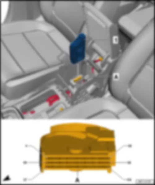
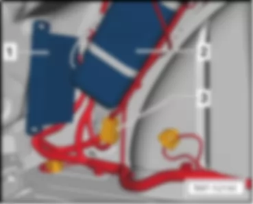
| 1 - | Mobile telephone operating electronics control unit -J412- |
| A - | 54-pin connector -T54- |
| B - | Connector -Antenne- |
|
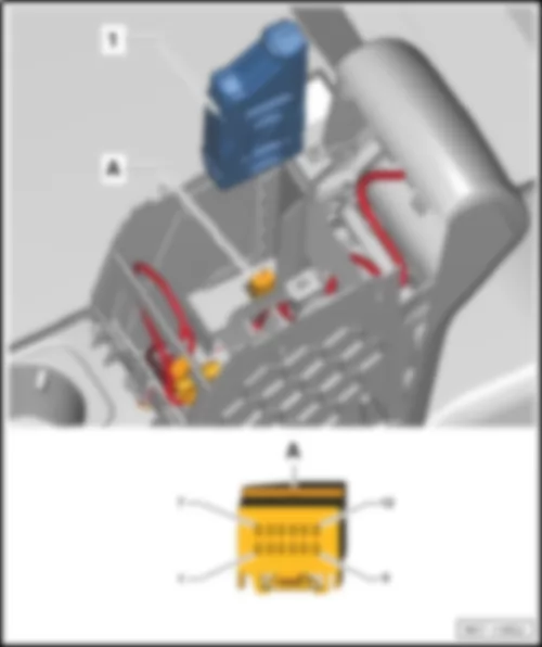
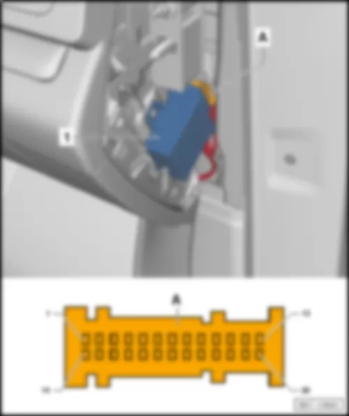
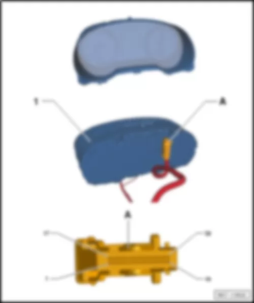
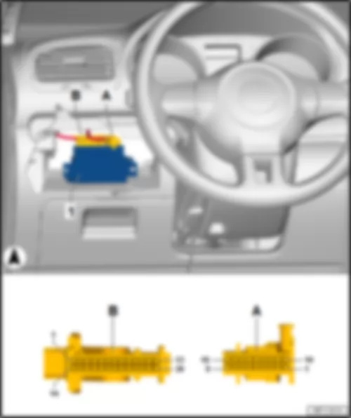
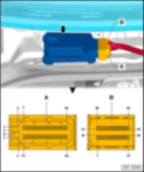
| 1 - | Multimedia system control unit -J650- |
| A - | 12-pin connector -T12t- |
Note
|
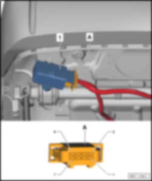
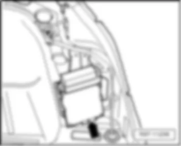
| 1 - | Mobile telephone operating electronics control unit -J412- |
| A - | 54-pin connector -T54b- |
|
| Connector assignment: |
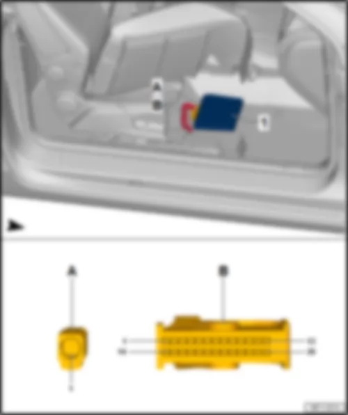
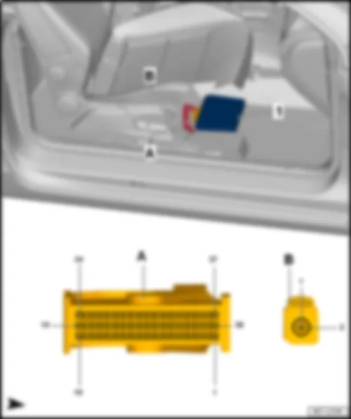
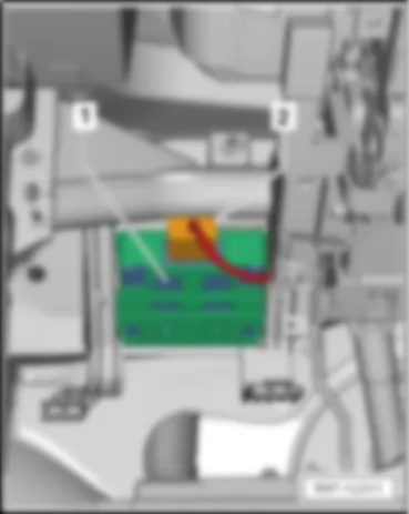
| 1 - | Heated front seats control unit -J774- |
| A - | 8-pin connector -T8z- on wiring harness |
|
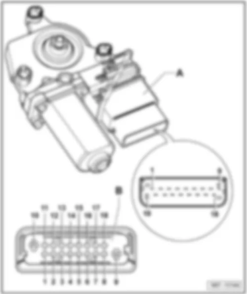
| Rear right window regulator motor -V27- |
| A - | Rear right window regulator motor -V27- |
| Connector: |
| B - | 18-pin connector -T18a- on wiring harness |
|
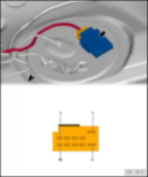
| Fuel pump control unit -J538- |
| - | Under right rear seat, -auf der Kraftstofffördereinheit- |
| - | 10-pin connector -T10n- , on wiring harness |
|
|
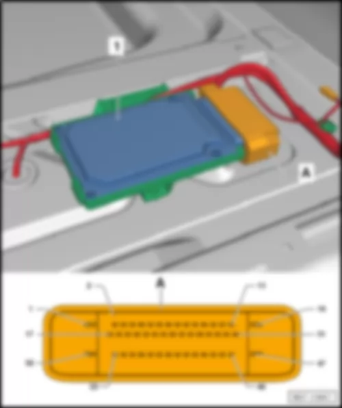
| Electronically controlled damping control unit -J250- |
| 1 - | Electronically controlled damping control unit -J250- |
| A - | 47-pin connector -T47d- , on wiring harness |
|
|
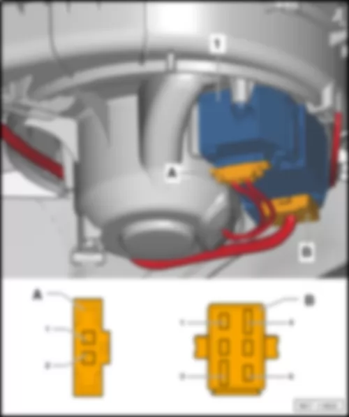
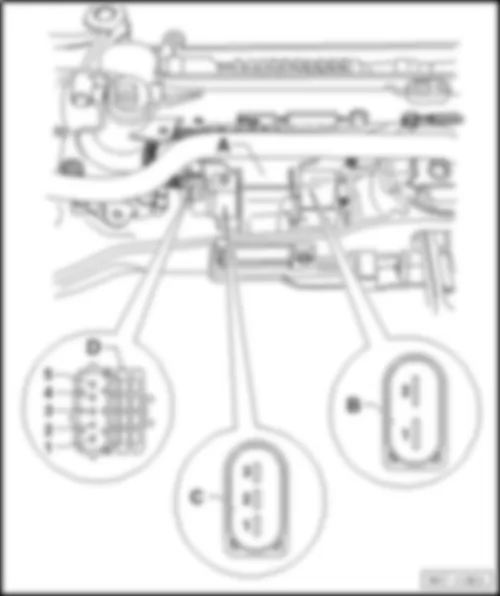
| Connector assignment: |
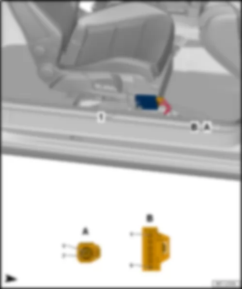
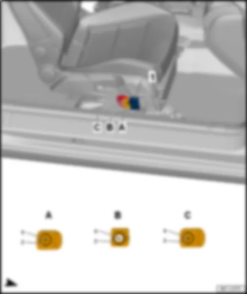
| A - | Trailer detector control unit -J345- |
| Connector: |
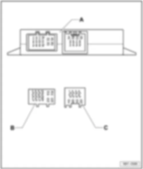
| B - | 16-pin connector -T16i- , on wiring harness |
| C - | 12-pin connector -T12h- , on wiring harness |
|
| 1 - | Blind spot monitor control unit -J1086- |
| A - | 8-pin connector -T8ap, schwarz- |
|
| -T8ap- (A) | Designation |
| 1 | |
| 2 | |
| 3 | Data bus diagnostic interface -J533- (can-h) |
| 4 | Data bus diagnostic interface -J533- (can-l) |
| 5 | Terminal 31 |
| 6 | CAN bus (can-h) |
| 7 | CAN bus (can-l) |
| 8 | Terminal 15 |
|
| 1 - | Blind spot monitor control unit 2 -J1087- |
| A - | 8-pin connector -T8ao, schwarz- |
|
| -T8ao- (A) | Designation |
| 1 | |
| 2 | |
| 3 | Blind Spot Monitor warning lamp in right exterior mirror -K304- (+) |
| 4 | Blind Spot Monitor warning lamp in left exterior mirror -K303- (+) |
| 5 | Terminal 31 |
| 6 | CAN bus (can-h) |
| 7 | CAN bus (can-l) |
| 8 | Terminal 15 |
|
|
| Rear left window regulator motor -V26- |
| A - | Rear left window regulator motor -V26- |
| B - | 18-pin connector -T18- |
|
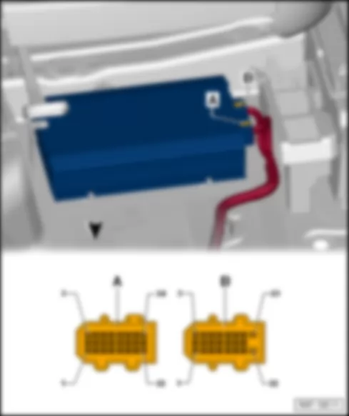
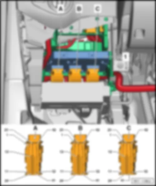
| - | Amplifier -R12- |
| A - | 24-pin connector -T24- |
| B - | 23-pin connector -T23- |
|

 Deutsch
 English
 English
 Español
 Français
 Nederlands

