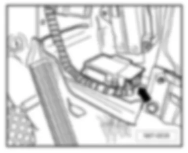
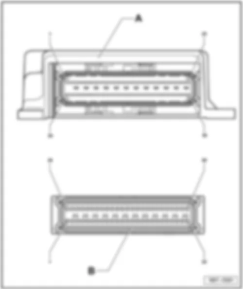
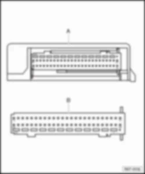
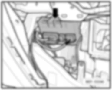
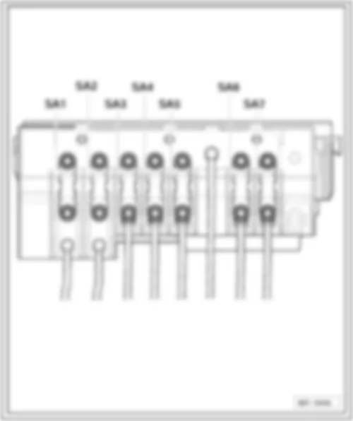
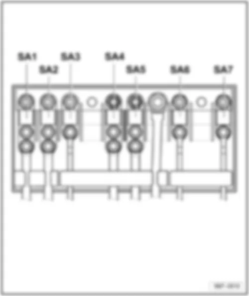
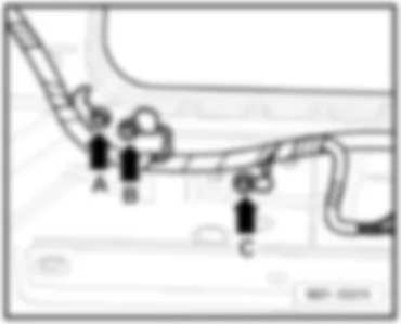
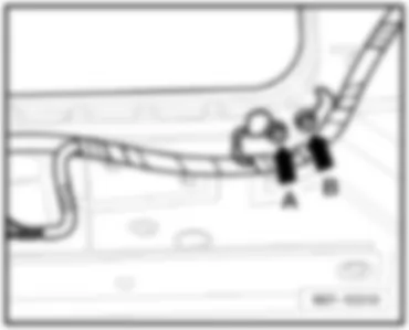
| No. | | Current Flow Diagram designation | Nominal value | | Function/component | Terminal |
| 1 | - | SA1-Fuse 1 on fuse holder A | 150A
200A | - | C-Alternator (90A/120A)
C-Alternator (140A) | 30a |
| 2 | - | SA2-Fuse 2 on fuse holder A | 80A | -
| J500-Power steering control unit
V187-Electromechanical power steering motor | 30a |
| 3 | - | SA3-Fuse 3 on fuse holder A | 50A | - | J293-Radiator fan control unit
V7-Radiator fan
V177-Radiator fan 2 | 30a |
| 4 | - | SA4-Fuse 4 on fuse holder A | - | - | Not assigned | 30a |
| 5 | - | SA5-Fuse 5 on fuse holder A | 80A
100A
| -
-
| -Fuses on fuse holder C, on left under dash panel SC18-SC24, SC42-SC56, (from November 2005)
J604-Auxiliary air heater control unit, (to November 2005)
Z35-Auxiliary air heater element, (to November 2005) | 30a |
| 6 | - | SA6-Fuse 6 on fuse holder A | 80A
100A
| -
-
| -Fuses on fuse holder C, on left under dash panel SC18-SC24, SC42-SC56, (to November 2005)
J604-Auxiliary air heater control unit (from November 2005)
Z35-Auxiliary air heater element (from November 2005) | 30a |
| 7 | - | SA7-Fuse 7 on fuse holder A | 50A | - | J345-Trailer detector control unit / preparation for trailer operation | 30a |
| No. | | Current Flow Diagram designation | Nominal value | | Function/component | Terminal |
| 1 | - | SA1-Fuse 1 on fuse holder A | 150A
200A | -
- | C-Alternator (90A/120A)
C-Alternator (140A) | 30a |
| 2 | - | SA2-Fuse 2 on fuse holder A | 80A | - | J500-Power steering control unit
V187-Electromechanical power steering motor | 30a |
| 3 | - | SA3-Fuse 3 on fuse holder A | 50A | - | J293-Radiator fan control unit
V7-Radiator fan
V177-Radiator fan 2 | 30a |
| 4 | - | SA4-Fuse 4 on fuse holder A | 5A
40A | - | J359-Low heat output relay (from November 2006)
Z35-Auxiliary air heater element (from November 2006) | 30a |
| 5 | - | SA5-Fuse 5 on fuse holder A | 100A | - | -Fuse on fuse holder C, on left under dash panel SC49 | 30a |
| 6 | - | SA6-Fuse 6 on fuse holder A | 5A
40A | - | J360-High heat output relay (from November 2006)
Z35-Auxiliary air heater element (from November 2006)
J604-Auxiliary air heater control unit (from November 2005)
Z35-Auxiliary air heater element (from November 2005) | 30a |
| 7 | -
| SA7-Fuse 7 on fuse holder A | 50A | - | -Special equipment | 30a |
| No. | | Current Flow Diagram designation | Nominal value | | Function/component | Terminal |
| 1 | - | SA1-Fuse 1 on fuse holder A | 150A
200A | - | C-Alternator (90A/110A)
C-Alternator (140A) | 30a |
| 2 | - | SA2-Fuse 2 on fuse holder A | 80A | - | V187-Motor for electromechanical power steering | 30a |
| 3 | - | SA3-Fuse 3 on fuse holder A | 80A | - | V7-Radiator fan | 30a |
| 4 | - | SA4-Fuse 4 on fuse holder A | - | - | Not assigned | - |
| 5 | - | SA5-Fuse 5 on fuse holder A | 100A | - | Z35-Auxiliary heater element | 30a |
| 6 | - | SA6-Fuse 6 on fuse holder A | 80A
100A | - | -Fuses on fuse holder on left of dash panel
-SC18 - SC24, SC42 - SC56
-Optional equipment | 30a |
| 7 | - | SA7-Fuse 7 on fuse holder A | - | - | Not assigned | - |
| No. | | Current Flow Diagram designation | Nominal value | | Function/component | Terminal |
| F1 | - | SB1-Fuse 1 on fuse holder B | 25A | -
| J400-Wiper motor control unit
V217-Front passenger side wiper motor | 30a |
| F2 | - | SB2-Fuse 2 on fuse holder B | 5A | - | J527-Steering column electronics control unit | 30a |
| F3 | - | SB3-Fuse 3 on fuse holder B | 5A | - | J519-Onboard supply control unit | 30a |
| F4 | - | SB4-Fuse 4 on fuse holder B | 30A | - | J104-ABS control unit | 30a |
| F5 | - | SB5-Fuse 5 on fuse holder B | 15A | - | J743-Mechatronics control unit | 30a |
| F6 | - | SB6-Fuse 6 on fuse holder B | 5A | - | J285-Control unit in dash panel insert | 30a |
| F7 | - | SB7-Fuse 7 on fuse holder B | - | - | - | - |
| F8 | - | SB8-Fuse 8 on fuse holder B | 15A | - | J503-Control unit with display for radio and navigation
R-Radio | 30a |
| F9 | - | SB9-Fuse 9 on fuse holder B | 5A | - | J412-Control unit for cellphone operating electronics | 30a |
| F10 | - | SB10-Fuse 10 on fuse holder B | 5A
10A
| -
-
| J317-Terminal 30 voltage supply relay (only vehicles with diesel engine)
J317-Terminal 30 voltage supply relay (vehicles with petrol engine, not engine codes BSE, BSF)
J623-Engine control unit (vehicles with petrol engine, not engine codes BSE, BSF) | 30a |
| F11 | - | SB11-Fuse 11 on fuse holder B | 20A | - | J364-Auxiliary heater control unit | 30a |
| F12 | - | SB12-Fuse 12 on fuse holder B | 5A | - | J533-Data bus diagnosis interface | 30a |
| No. | | Current Flow Diagram designation | Nominal value | | Function/component | Terminal |
| F13 | - | SB13-Fuse 13 on fuse holder B | 30A
25A
| -
-
| J623-Engine control unit (only vehicles with diesel engine)
J623-Petrol engine control unit (only vehicles with petrol engine) | 87a |
| F14 | - | SB14-Fuse 14 on fuse holder B | 20A | - | N152-Ignition transformer
N70-Ignition coil 1 with output stage
N127-Ignition coil 2 with output stage
N291-Ignition coil 3 with output stage
N292-Ignition coil 4 with output stage | 87a |
| F15 | - | SB15-Fuse 15 on fuse holder B | 15A
5A | -
- | G108-Lambda probe 2 before catalytic converter
G130-Lambda probe after catalytic converter
G131-Lambda probe 2 after catalytic converter
G287-Lambda probe 3 after catalytic converter
J17-Fuel pump relay
J179-Automatic glow period control unit | 87a |
| F16 | - | SB16-Fuse 16 on fuse holder B | 30A | - | J104-ABS control unit | 30a |
| F17 | - | SB17-Fuse 17 on fuse holder B | 15A | - | H2-Treble tone horn
H7-Bass tone horn | 30a |
| F18 | - | SB18-Fuse 18 on fuse holder B | 30A | - | J608-Special vehicle control unit
R12-Amplifier | 30a |
| F19 | - | SB19-Fuse 19 on fuse holder B | 30A | - | J400-Wiper motor control unit
V216-Driver side windscreen wiper motor | 30a |
| F20 | - | SB20-Fuse 20 on fuse holder B | - | - | Not assigned | 30a |
| F21 | - | SB21-Fuse 21 on fuse holder B | 15A | - | G39-Lambda probe
G130-Lambda probe after catalytic converter
J583-NOx sensor control unit | 87a |
| No. | | Current Flow Diagram designation | Nominal value | | Function/component | Terminal |
| F22 | - | SB22-Fuse 22 on fuse holder B | 5A | -
| F47-Brake pedal switch
G476-Clutch position sender | 87a |
| F23 | - | SB23-Fuse 23 on fuse holder B | 5A
10A
15A | -
-
- | J299-Secondary air pump relay
N18-Exhaust gas recirculation valve
N75-Charge pressure control solenoid valve
N345-Exhaust gas recirculation cooler changeover valve
N381-Exhaust gas recirculation cooler changeover valve 2
N276-Fuel pressure regulating valve | 87a |
| F24 | - | SB24-Fuse 24 on fuse holder B | 10A | - | F265-Map-controlled engine cooling system thermostat
J293-Radiator fan control unit
N18-Exhaust gas recirculation valve
N80-Activated charcoal filter solenoid valve 1
N156-Variable intake manifold changeover valve
N205-Inlet camshaft control valve 1
N316-Intake manifold flap valve
V157-Intake manifold flap motor | 87a |
| F25 | - | SB25-Fuse 25 on fuse holder B | 40A | - | J519-Onboard supply control unit | 30a |
| F26 | - | SB26-Fuse 26 on fuse holder B | 40A | - | J519-Onboard supply control unit | 30a |
| F27 | - | SB27-Fuse 27 on fuse holder B | 50A | - | J179-Automatic glow period control unit | 30a |
| F28 | - | SB28-Fuse 28 on fuse holder B | 40A | - | J681-Terminal 15 voltage supply relay 2 | 30a |
| F29 | - | SB29-Fuse 29 on fuse holder B | - | - | Not assigned | 30a |
| F30 | - | SB30-Fuse 30 on fuse holder B | 40A | - | J59-X-contact relief relay (SC7, SC8, SC28 - SC35) | 30a |
| No. | | Current Flow Diagram designation | Nominal value | | Function/component | Terminal |
| F1 | - | SB1-Fuse 1 on fuse holder B | 25A
| -
| J400-Wiper motor control unit
V217-Front passenger side wiper motor | 30a |
| F2 | - | SB2-Fuse 2 on fuse holder B | 5A | - | J527-Steering column electronics control unit | 30a |
| F3 | - | SB3-Fuse 3 on fuse holder B | 5A | - | J519-Onboard supply control unit | 30a |
| F4 | - | SB4-Fuse 4 on fuse holder B | 30A | - | J104-ABS control unit | 30a |
| F5 | - | SB5-Fuse 5 on fuse holder B | 15A | - | J743-Mechatronics control unit | 30a |
| F6 | - | SB6-Fuse 6 on fuse holder B | 5A | - | J285-Control unit in dash panel insert | 30a |
| F7 | - | SB7-Fuse 7 on fuse holder B | - | - | -Not assigned | - |
| F8 | - | SB8-Fuse 8 on fuse holder B | 15A
| -
| J503-Control unit with display for radio and navigation
R-Radio | 30a |
| F9 | - | SB9-Fuse 9 on fuse holder B | 5A | - | J412-Control unit for cellphone operating electronics | 30a |
| F10 | - | SB10-Fuse 10 on fuse holder B | 5A
10A
10A | -
- | J317-Terminal 30 voltage supply relay
J317-Terminal 30 voltage supply relay
J623-Engine control unit | 30a |
| F11 | - | SB11-Fuse 11 on fuse holder B | 20A | - | J364-Auxiliary heater control unit | 30a |
| F12 | - | SB12-Fuse 12 on fuse holder B | 5A | - | J533-Data bus diagnosis interface | 30a |
| F13 | - | SB12-Fuse 12 on fuse holder B | 30A
25A
| -
-
| J623-Engine control unit (only vehicles with diesel engine)
J623-Petrol engine control unit (only vehicles with petrol engine) | 87a |
| F14 | - | SB14-Fuse 14 on fuse holder B | 20A
| -
| N152-Ignition transformer
N70-Ignition coil 1 with output stage
N127-Ignition coil 2 with output stage
N291-Ignition coil 3 with output stage
N292-Ignition coil 4 with output stage | 87a |
| No. | | Current Flow Diagram designation | Nominal value | | Function/component | Terminal |
| F15 | - | SB15-Fuse 15 on fuse holder B | 15A
5A
10A
| -
-
-
| G108-Lambda probe 2 before catalytic converter
G130-Lambda probe after catalytic converter
G131-Lambda probe 2 after catalytic converter
G287-Lambda probe 3 after catalytic converter
Z29-Heater for Lambda probe 1 after catalytic converter
J360-High heat output relay
G39-Lambda probe
Z19-Heater for Lambda probe
J17-Fuel pump relay
J179-Automatic glow period control unit
N30-Injector, cylinder 1 (BUD)
N31-Injector, cylinder 2 (BUD)
N32-Injector, cylinder 3 (BUD)
N33-Injector, cylinder 4 (BUD) | 87a |
| F16 | - | SB16-Fuse 16 on fuse holder B | 30A | - | J104-ABS control unit | 30a |
| F17 | - | SB17-Fuse 17 on fuse holder B | 15A
| -
| H2-Treble tone horn
H7-Bass tone horn | 30a |
| F18 | - | SB18-Fuse 18 on fuse holder B | 30A
| -
| J608-Special vehicle control unit
R12-Amplifier | 30a |
| F19 | - | SB19-Fuse 19 on fuse holder B | 30A
| -
| J400-Wiper motor control unit
V216-Driver side windscreen wiper motor | 30a |
| F20 | - | SB20-Fuse 20 on fuse holder B | - | - | -Not assigned | 30a |
| F21 | - | SB21-Fuse 21 on fuse holder B | 15A
| -
| G39-Lambda probe
G130-Lambda probe after catalytic converter
N421-Magnetic clutch for supercharger
Z19-Lambda probe heater
Z28-Lambda probe heater 2 | 87a |
| No. | | Current Flow Diagram designation | Nominal value | | Function/component | Terminal |
F22
| -
| SB22-Fuse 22 on fuse holder B
| 5A
| -
| F47-Brake pedal switch
G476-Clutch position sender | 87a
|
| F23 | - | SB23-Fuse 23 on fuse holder B | 5A
10A
15A | -
-
- | J299-Secondary air pump relay
N18-Exhaust gas recirculation valve
N75-Charge pressure control solenoid valve
N345-Exhaust gas recirculation cooler changeover valve
N381-Exhaust gas recirculation cooler changeover valve 2
N276-Fuel pressure regulating valve | 87a |
| F24 | - | SB24-Fuse 24 on fuse holder B | 10A | - | F265-Map-controlled engine cooling system thermostat
J293-Radiator fan control unit
N18-Exhaust gas recirculation valve
N80-Activated charcoal filter system solenoid valve 1
N156-Variable intake manifold changeover valve
N205-Inlet camshaft control valve 1
N316-Intake manifold flap valve
V157-Intake manifold flap motor
V50-Continued coolant circulation pump
N249-Turbocharger air circulation valve
N745-Charge pressure control solenoid | 87a |
| F25 | - | SB25-Fuse 25 on fuse holder B | 40A | - | J519-Onboard supply control unit | 30a |
| F26 | - | SB26-Fuse 26 on fuse holder B | 40A | - | J519-Onboard supply control unit | 30a |
| F27 | - | SB27-Fuse 27 on fuse holder B | 50A | - | J179-Automatic glow period control unit | 30a |
| F28 | - | SB28-Fuse 28 on fuse holder B | 40A | - | J681-Terminal 15 voltage supply relay 2 | 30a |
| F29 | - | SB29-Fuse 29 on fuse holder B | - | - | - | 30a |
| F30 | - | SB30-Fuse 30 on fuse holder B | 40A | - | J59-X-contact relief relay (SC7, SC8, SC28 - SC35) | 30a |
| No. | | Current Flow Diagram designation | Nominal value | | Function/component | Terminal |
| F1 | - | SB1-Fuse 1 on fuse holder B | 30A | - | J104-ABS with EDL control unit | 30a |
| F2 | - | SB2-Fuse 2 on fuse holder B | 30A | - | J104-ABS with EDL control unit | 30a |
| F3 | - | SB3-Fuse 3 on fuse holder B | 25A | - | V217-Front passenger side windscreen wiper motor | 30a |
| F4 | - | SB4-Fuse 4 on fuse holder B | 5A | - | J519-Onboard supply control unit | 30a |
| F5 | - | SB5-Fuse 5 on fuse holder B | 20A | - | H2-Treble tone horn
H7-Bass tone horn | 30a |
| F6 | - | SB6-Fuse 6 on fuse holder B | 15A
20A | - | N276-Fuel pressure regulating valve (BLF)
N...-Ignition coils 1-4 with output stage (BCA) | 87a |
| F7 | - | SB7-Fuse 7 on fuse holder B | 5A | - | F47-Brake pedal switch
G476-Clutch position sender | 87a |
| F8 | - | SB8-Fuse 8 on fuse holder B | 10A | - | J293-Radiator fan control unit (BCA, BLF)
N80-Activated charcoal filter solenoid valve 1 (BCA, BLF)
N205-Camshaft adjustment valve 1 (BLF)
N316-Intake manifold flap valve (BLF)
V157-Intake manifold flap motor (BKD, BKC, BKD, AZV) | 87a |
| F9 | - | SB9-Fuse 9 on fuse holder B | 10A | - | J17-Fuel pump relay (BKC, BKD)
J179-Automatic glow period control unit (BKC, BKD, AZV)
J317-Relay for voltage supply of term. 30 (BKC, BKD, BCA, AZV, BLF) | 87a |
| F10 | - | SB10-Fuse 10 on fuse holder B | 10A | - | N18-Exhaust gas recirculation valve (BKC, BKD, AZV)
N75-Charge pressure control solenoid valve (BKC, BKD, AZV)
N345-Exhaust gas recirculation cooler changeover valve (BKC, BKD, AZV) | 87a |
| No. | | Current Flow Diagram designation | Nominal value | | Function/component | Terminal |
| F11 | - | SB11-Fuse 11 on fuse holder B | 25A
30A | - | J220-Motronic control unit (BCA, BLF)
J248-Diesel direct injection system control unit (BKC, BKD) | 87a |
| F12 | - | SB12-Fuse 12 on fuse holder B | 15A | - | G39-Lambda probe (BLF, BCA)
G130-Lambda probe after catalytic converter (BLF, BCA) | 87a |
| F13 | - | SB13-Fuse 13 on fuse holder B | 15A | - | J743-Mechatronic unit for double clutch gearbox | 30a |
| F14 | - | SB14-Fuse 14 on fuse holder B | - | - | Not assigned | - |
| F15 | - | SB15-Fuse 15 on fuse holder B | 40A | - | B-Starter (terminal 50) | 50 |
| F16 | - | SB16-Fuse 16 on fuse holder B | 15A | - | J527-Steering column electronics control unit | 30a |
| F17 | - | SB17-Fuse 17 on fuse holder B | 10A | - | J285-Control unit in dash panel insert | 30a |
| F18 | - | SB18-Fuse 18 on fuse holder B | 30A | - | R12-Amplifier | 30a |
| F19 | - | SB19-Fuse 19 on fuse holder B | 15A | - | R-Radio
J503-Control unit with display for radio and navigation system | 30a |
| F20 | - | SB20-Fuse 20 on fuse holder B | 10A | - | J412-Control unit for cellphone operating electronics | 30a |
| F21 | - | SB21-Fuse 21 on fuse holder B | - | - | Not assigned | - |
| F22 | - | SB22-Fuse 22 on fuse holder B | - | - | Not assigned | - |
| F23 | - | SB23-Fuse 23 on fuse holder B | - | - | Not assigned | - |
| F24 | - | SB24-Fuse 24 on fuse holder B | 10A | - | J533-Data bus diagnosis interface | 30a |
| F25 | - | SB25-Fuse 25 on fuse holder B | - | - | Not assigned | - |
| No. | | Current Flow Diagram designation | Nominal value | | Function/component | Terminal |
| F26 | - | SB26-Fuse 26 on fuse holder B | 10A
5A | - | J220-Motronic control unit (BCA, BLF)
J317-Terminal 30 voltage supply relay | 30a |
| F27 | - | SB27-Fuse 27 on fuse holder B | 10A | - | N79-Heater element for crankcase breather | 15a |
| F28 | - | SB28-Fuse 28 on fuse holder B | 20A | - | J217-Automatic gearbox control unit | 15a |
| F29 | - | SB29-Fuse 29 on fuse holder B | 20A
10A | - | N...-Ignition coil 1 - 4 with power output stage
N...-Number 1 - 4 cylinder injector (BCA) | 15a |
| F30 | - | SB30-Fuse 30 on fuse holder B | 20A | - | J364-Auxiliary heater control unit | 30a |
| F31 | - | SB31-Fuse 31 on fuse holder B | 25A | - | V216-Driver side windscreen wiper motor | 30a |
| F32 | - | SB32-Fuse 32 on fuse holder B | - | - | Not assigned | - |
| F33 | - | SB33-Fuse 33 on fuse holder B | 15A | - | G6-Fuel system pressurisation pump (BCA)
J17-Fuel pump relay (BKC, BKD) | 30a |
| F34 | - | SB34-Fuse 34 on fuse holder B | - | - | Not assigned | - |
| F35 | - | SB35-Fuse 35 on fuse holder B | - | - | Not assigned | - |
| F36 | - | SB36-Fuse 36 on fuse holder B | - | - | Not assigned | - |
| F37 | - | SB37-Fuse 37 on fuse holder B | | - | Not assigned | - |
| F38 | - | SB38-Fuse 38 on fuse holder B | 10A | - | V48-Left headlight range control motor
V49-Right headlight range control motor | 15a |
| F39 | - | SB39-Fuse 39 on fuse holder B | 5A | - | G226-Oil level and oil temperature sender | 15a |
| F40 | - | SB40-Fuse 40 on fuse holder B | 20A | - | Fuses on fuse holder C, left (SC1 - SC6, SC9 -SC16, SC25 - SC27) | 15a |
| No. | | Current Flow Diagram designation | Nominal value | | Function/component | Terminal |
| F41 | - | SB41-Fuse 41 on fuse holder B | - | - | Not assigned | - |
| F42 | - | SB42-Fuse 42 on fuse holder B | 10A
5A | - | G70-Air mass meter (BKD, BKC, AZV)
J757-Engine components current supply relay (BCA) | 15a |
| F43 | - | SB43-Fuse 43 on fuse holder B | 20A | - | V192-Vacuum pump for brakes (BLF) | 15a |
| F44 | - | SB44-Fuse 44 on fuse holder B | - | - | Not assigned | - |
| F45 | - | SB45-Fuse 45 on fuse holder B | - | - | Not assigned | - |
| F46 | - | SB46-Fuse 46 on fuse holder B | - | - | Not assigned | - |
| F47 | - | SB47-Fuse 47 on fuse holder B | 40A | - | J519-Onboard supply control unit | 30a |
| F48 | - | SB48-Fuse 48 on fuse holder B | 40A | - | J519-Onboard supply control unit | 30a |
| F49 | - | SB49-Fuse 49 on fuse holder B | - | - | Not assigned | - |
| F50 | - | SB50-Fuse 50 on fuse holder B | - | - | Not assigned | - |
| F51 | - | SB51-Fuse 51 on fuse holder B | 50A | - | J179-Automatic glow period control unit (AZV, BKC, BKD) | 30a |
| F52 | - | SB52-Fuse 52 on fuse holder B | 50A | - | J519-Onboard supply control unit | 30a |
| F53 | - | SB53-Fuse 53 on fuse holder B | 50A | - | SD1-Fuse 1 on fuse holder D (seat adjustment) | 30a |
| F54 | - | SB54-Fuse 54 on fuse holder B | 50A | - | J293-Radiator fan control unit | 30a |
| No. | | Current Flow Diagram designation | Nominal value | | Function/component | Terminal |
| 1 | - | SC1-Fuse 1 on fuse holder C | 5A | - | J412-Control unit for cellphone operating electronics
Y7-Automatic anti-dazzle interior mirror | 15a |
| 2 | - | SC2-Fuse 2 on fuse holder C | 5A | - | J345-Trailer detector control unit/ preparation for tow bar | 15a |
| 3 | - | SC3-Fuse 3 on fuse holder C | 5A | -
| E102-Headlight range control regulator
V48-Left headlight range control motor
V49-Right headlight range control motor | 15A |
| 4 | - | SC4-Fuse 4 on fuse holder C | 5A | - | J530-Garage door operation control unit | 15a |
| 5 | - | SC5-Fuse 5 on fuse holder C | 5A | - | H28-Driving school mode warning buzzer | 15a |
| 6 | - | SC6-Fuse 6 on fuse holder C | 10A | - | G70-Air mass meter
N79-Heater element for crankcase breather | 15a |
| 7 | - | SC7-Fuse 7 on fuse holder C | - | - | -Not assigned | 75a |
| 8 | - | SC8-Fuse 8 on fuse holder C | - | - | -Not assigned | 75a |
| 9 | - | SC9-Fuse 9 on fuse holder C | 5A | - | J234-Airbag control unit
K145-Front passenger side airbag deactivated warning lamp | 15a |
| 10 | - | SC10-Fuse 10 on fuse holder C | 10A | - | N30-Cylinder 1 injector (BSE, BSF)
N31-Cylinder 2 injector (BSE, BSF)
N32-Cylinder 3 injector (BSE, BSF)
N33-Cylinder 4 injector (BSE, BSF) | 15a |
| 11 | - | SC11-Fuse 11 on fuse holder C | 5A | - | F189-Tiptronic switch
J285-Control unit in dash panel insert
J500-Power steering control unit
J533-Data bus diagnosis interface
J587-Selector lever sensors control unit
J743-Mechatronics for double clutch gearbox | 15a |
| No. | | Current Flow Diagram designation | Nominal value | | Function/component | Terminal |
| 12 | - | SC12-Fuse 12 on fuse holder C | 5A | - | J485-Relay for auxiliary heater operation | 15a |
| 13 | - | SC13-Fuse 13 on fuse holder C | 5A | - | E132-Traction control system switch
E256-Button for TCS and ESP
E492-Button for tyre pressure monitor
G65-High pressure sender
G266-Oil level and oil temperature sender
J131-Heated driver seat control unit
J132-Heated front passenger seat control unit
J255-Climatronic control unit
K216-Warning lamp 2 for ESP and TCS | 15a |
| 14 | - | SC14-Fuse 14 on fuse holder C | 5A | - | J104-ABS control unit
F-Brake light switch, from November 2005 | 15a |
| 15 | - | SC15-Fuse 15 on fuse holder C | 10A | - | J17-Fuel pump relay
J317-Terminal 30 voltage supply relay
J538-Fuel pump control unit
J623-Engine control unit
T16-16-pin connector, self-diagnosis connection | 15a |
| 16 | - | SC16-Fuse 16 on fuse holder C | - | - | V319-Right dynamic cornering light control motor | 15a |
| 17 | - | SC17-Fuse 17 on fuse holder C | - | - | -Not assigned | 15a |
| 18 | - | SC18-Fuse 18 on fuse holder C | 5A | - | J104-ABS control unit | 30a |
| 19 | - | SC19-Fuse 19 on fuse holder C | - | - | G396-Accident data memory | - |
| 20 | - | SC20-Fuse 20 on fuse holder C | 5A | - | J217-Automatic gearbox control unit | 30a |
| 21 | - | SC21-Fuse 21 on fuse holder C | 7.5A | - | J519-Onboard supply control unit | 30a |
| No. | | Current Flow Diagram designation | Nominal value | | Function/component | Terminal |
| 22 | - | SC22-Fuse 22 on fuse holder C | 10A | - | E16-Heater/heat output switch
J255-Climatronic control unit
J301-Air conditioning system control unit
R149-Remote control receiver for auxiliary coolant heater | 30a |
| 23 | - | SC23-Fuse 23 on fuse holder C | 10A | - | E1-Light switch
F-Brake light switch, from November 2005
T16-Diagnosis connection | 30a |
| 24 | - | SC24-Fuse 24 on fuse holder C | 10A | - | J386-Driver door control unit (central locking)
J387-Front passenger door control unit (central locking) | 30a |
| 25 | - | SC25-Fuse 25 on fuse holder C | 20A | - | J217-Automatic gearbox control unit | 15a |
| 26 | - | SC26-Fuse 26 on fuse holder C | 20A | - | V192-Vacuum pump for brakes | 15a |
| 27 | - | SC27-Fuse 27 on fuse holder C | 10A | - | V318-Left dynamic cornering light control motor | 15a |
| 28 | - | SC28-Fuse 28 on fuse holder C | 15A | - | V12-Rear window wiper motor | 75a |
| 29 | - | SC29-Fuse 29 on fuse holder C | 15A | - | J519-Onboard supply control unit (dual washer pump) | 75a |
| 30 | - | SC30-Fuse 30 on fuse holder C | 5A | - | E1-Lighting switch | 75a |
| 31 | - | SC31-Fuse 31 on fuse holder C | 5A | - | E94-Heated driver seat regulator
E95-Heated front passenger seat regulator
Z20-Left washer jet heater element
Z21-Right washer jet heater element | 75a |
| 32 | - | SC32-Fuse 32 on fuse holder C | 20A | - | U1-Cigarette lighter (up to May 2006)
U5-12 V socket, in front of centre console (driving school equipment) (up to May 2006)
U9-Rear cigarette lighter (up to May 2006) | 75a |
| 33 | - | SC33-Fuse 33 on fuse holder C | 40A | - | E9-Fresh air blower switch
E16-Heater/heat output switch
J13-Fresh air blower relay
J301-Air conditioning system control unit
J485-Auxiliary heater operation relay | 75a |
| No. | | Current Flow Diagram designation | Nominal value | | Function/component | Terminal |
| 34 | - | SC34-Fuse 34 on fuse holder C | - | - | -Not assigned | 75a |
| 35 | - | SC35-Fuse 35 on fuse holder C | - | - | -Not assigned | 75a |
| 36 | - | SC36-Fuse 36 on fuse holder C | - | - | -Not assigned | - |
| 37 | - | SC37-Fuse 37 on fuse holder C | 30A | - | U13-AC/DC converter with socket, 12 V-230 V | 30a |
| 38 | - | SC38-Fuse 38 on fuse holder | - | - | -Not assigned | - |
| 39 | - | SC39-Fuse 39 on fuse holder C | 15A | -
| J345-Trailer detector control unit/ preparation for tow bar | 30a |
40
| -
| SC40-Fuse 40 on fuse holder C
| 15A
| -
| J345-Trailer detector control unit/ preparation for tow bar | 30a
|
41
| -
| SC41-Fuse 41 on fuse holder C
| 20A
| -
| J345-Trailer detector control unit/ preparation for tow bar | 30a
|
| 42 | - | SC42-Fuse 42 on fuse holder C | 5A | - | G397-Rain and light detection sensor
J515-Aerial selection control unit
G197-Magnetic field sender for compass | 30a |
| 43 | - | SC43-Fuse 43 on fuse holder C | 5A | - | G273-Interior monitoring sensor
G384-Vehicle inclination sender
H12-Alarm horn
R12-Amplifier | 30a |
| 44 | - | SC44-Fuse 44 on fuse holder C | 25A | -
| J13-Fresh air blower relay
J519-Onboard supply control unit (heated rear window) | 30a |
| 45 | - | SC45-Fuse 45 on fuse holder C | 30A | - | J386-Driver door control unit (window regulator)
J387-Front passenger door control unit (window regulator) | 30a |
| 46 | - | SC46-Fuse 46 on fuse holder C | 30A | - | J388-Rear left door control unit (window regulator)
J389-Rear right door control unit (window regulator) | 30a |
| No. | | Current Flow Diagram designation | Nominal value | | Function/component | Terminal |
47
| -
| SC47-Fuse 47 on fuse holder C
| 5A
| -
| G6-Fuel pump
J17-Fuel pump relay
J538-Fuel pump control unit
J643-Fuel supply relay | 30a
|
| 48 | - | SC48-Fuse 48 on fuse holder C | 25A | - | J393-Convenience system central control unit | 30a |
49
| -
| SC49-Fuse 49 on fuse holder C
| 25A
| -
| T4av-4-pin connector, voltage supply of equipment for disabled persons
U1-Cigarette lighter (to November 2005)
U5-12 V socket, in front centre console (driving school equipment) (to November 2005)
U9-Rear cigarette lighter (to November 2005) | 30a
|
50
| -
| SC50-Fuse 50 on fuse holder C
| 30A
| -
| J131-Heated driver seat control unit
J132-Heated front passenger seat control unit | 30a |
| 51 | - | SC51-Fuse 51 on fuse holder C | 25A | - | J245-Sunroof control unit
J650-Multimedia system control unit | 30a |
| 52 | - | SC52-Fuse 52 on fuse holder C | 20A | - | J39-Headlight washer system relay | 30a |
53
| -
| SC53-Fuse 53 on fuse holder C
| 15A
| -
| V125-Driver seat lumbar support longitudinal adjustment motor
V126-Front passenger seat lumbar support longitudinal adjustment motor
V129-Driver seat lumbar support height adjustment motor
V130-Front passenger seat lumbar support height adjustment motor | 30a
|
| 54 | - | SC54-Fuse 54 on fuse holder C | 20A | - | U5-12 V socket, in right luggage compartment | 30a |
55
| -
| SC55-Fuse 55 on fuse holder C
| 5A
| -
| F125-Multifunction switch
F189-Tiptronic switch
J446-Parking aid control unit
J587-Selector lever sensors control unit | 30a
|
| No. | | Current Flow Diagram designation | Nominal value | | Function/component | Terminal |
| 1 | - | SC1-Fuse 1 on fuse holder C | - | - | -Not assigned | 15a |
| 2 | - | SC2-Fuse 2 on fuse holder C | - | - | -Not assigned | 15a |
| 3 | - | SC3-Fuse 3 on fuse holder C | - | - | -Not assigned | 15A |
| 4 | - | SC4-Fuse 4 on fuse holder C | - | - | -Not assigned | 15a |
| 5 | - | SC5-Fuse 5 on fuse holder C | - | - | -Not assigned | 15a |
| 6 | - | SC6-Fuse 6 on fuse holder C | - | - | -Not assigned | 15a |
| 7 | - | SC7-Fuse 7 on fuse holder C | - | - | -Not assigned | 75a |
| 8 | - | SC8-Fuse 8 on fuse holder C | - | - | -Not assigned | 75a |
| 9 | - | SC9-Fuse 9 on fuse holder C | 5A | - | J234-Airbag control unit
K145-Front passenger side airbag deactivated warning lamp | 15a |
| 10 | - | SC10-Fuse 10 on fuse holder C | - | - | -Not assigned | 15a |
| 11 | - | SC11-Fuse 11 on fuse holder C | - | - | -Not assigned | 15a |
| 12 | - | SC12-Fuse 12 on fuse holder C | 5A | - | V318-Left dynamic cornering light control motor | 15a |
| No. | | Current Flow Diagram designation | Nominal value | | Function/component | Terminal |
| 14 | - | SC14-Fuse 14 on fuse holder C | 10A | - | E313-Selector lever
E1-Light switch
E256-TCS and ESP button
E492-Tyre pressure monitor display button
F-Brake light switch, from November 2005
F125-Multifunction switch
F189-Tiptronic switch
J17-Fuel pump relay
J104-ABS control unit
J217-Automatic gearbox control unit
J317-Terminal 30 voltage supply relay
J345-Trailer detector control unit/ towing mode preparation
J500-Power steering control unit
J538-Fuel pump control unit
J623-Engine control unit
J743-Mechatronic unit for dual clutch gearbox
L13-Left gas discharge (xenon) bulb
L14-Right gas discharge (xenon) bulb | 15a |
15
|
-
|
SC15-Fuse 15 on fuse holder C
| 10A |
-
| E102-Headlight range control regulator
G70-Air mass meter
N79-Heater element for crankcase breather
J13-Fresh air blower relay
J587-Selector lever sensors control unit
J745-Cornering light and headlight range control unit
T16-Diagnostic connection | 15a |
| 16 | - | SC16-Fuse 16 on fuse holder C | 10A | - | V319-Right dynamic cornering light control motor | 15a |
| 17 | - | SC17-Fuse 17 on fuse holder C | - | - | -Not assigned | 15a |
| 18 | - | SC18-Fuse 18 on fuse holder C | 5A | - | -Not assigned | 30a |
| 19 | - | SC19-Fuse 19 on fuse holder C | 5A | - | G396-Accident data memory | 30a |
| No. | | Current Flow Diagram designation | Nominal value | | Function/component | Terminal |
| 20 | - | SC20-Fuse 20 on fuse holder C | 10A | - | E16-Heater/heat output switch
E313-Selector lever
J217-Automatic gearbox control unit
J255-Climatronic control unit
J301-Air conditioning system control unit
J446-Parking aid control unit
R149-Remote control receiver for auxiliary coolant heater
J104-ABS control unit, on right in engine compartment | 30a |
| 21 | - | SC21-Fuse 21 on fuse holder C | 7.5A | - | J519-Onboard supply control unit | 30a |
| 22 | - | SC22-Fuse 22 on fuse holder C | 5A | - | G273-Interior monitoring sensor
G384-Vehicle inclination sender
H12-Alarm horn | 30a |
| 23 | - | SC23-Fuse 23 on fuse holder C | 10A | - | E1-Light switch
G197-Magnetic field sender for compass
G397-Rain and light detector sensor
T16-Diagnostic connection | 30a |
| 24 | - | SC24-Fuse 24 on fuse holder C | 10A | - | J386-Driver door control unit (central locking)
J387-Front passenger door control unit (central locking) | 30a |
| 25 | - | SC25-Fuse 25 on fuse holder C | 20A | - | J217-Automatic gearbox control unit | 15a |
| 26 | - | SC26-Fuse 26 on fuse holder C | 20A | - | V192-Vacuum pump for brakes | 15a |
| 27 | - | SC27-Fuse 27 on fuse holder C | - | - | -Not assigned | 15a |
| 28 | - | SC28-Fuse 28 on fuse holder C | 20A | - | V12-Rear window wiper motor | 75a |
| No. | | Current Flow Diagram designation | Nominal value | | Function/component | Terminal |
| 29 | - | SC29-Fuse 29 on fuse holder C | 15A | - | J519-Onboard supply control unit (dual washer pump) | 75a |
| 30 | - | SC30-Fuse 30 on fuse holder C | 20A | - | U5-12 V socket, right in luggage compartment
U1-Cigarette lighter (up to November 2005)
U5-12 V socket, in front of centre console (driving school equipment) (up to November 2005)
U9-Rear cigarette lighter (up to November 2005) | 75a |
| 31 | - | SC31-Fuse 31 on fuse holder C | - | - | -Not assigned | 75a |
| 32 | - | SC32-Fuse 32 on fuse holder C | - | - | -Not assigned | 75a |
| 33 | - | SC33-Fuse 33 on fuse holder C | 40A | - | J13-Fresh air blower relay
E9-Fresh air blower switch | 75a |
| 34 | - | SC34-Fuse 34 on fuse holder C | - | - | -Not assigned | 75a |
| 35 | - | SC35-Fuse 35 on fuse holder C | - | - | -Not assigned | 75a |
| 36 | - | SC36-Fuse 36 on fuse holder C | - | - | -Not assigned | - |
| 37 | - | SC37-Fuse 37 on fuse holder C | - | - | -Not assigned | 30a |
| 38 | - | SC38-Fuse 38 on fuse holder | - | - | -Not assigned | - |
39
| -
| SC39-Fuse 39 on fuse holder C
| 15A
| -
| J345-Trailer detector control unit/ preparation for tow bar | 30a |
40
| -
| SC40-Fuse 40 on fuse holder C
| 15A
| -
| J345-Trailer detector control unit/ preparation for tow bar | 30a |
41
| -
| SC41-Fuse 41 on fuse holder C
| 20A
| -
| J345-Trailer detector control unit/ preparation for tow bar | 30a |
| No. | | Current Flow Diagram designation | Nominal value | | Function/component | Terminal |
| 42 | - | SC42-Fuse 42 on fuse holder C | 15A | - | V125-Driver seat lumbar support longitudinal adjustment motor
V126-Front passenger seat lumbar support longitudinal adjustment motor
V129-Driver seat lumbar support height adjustment motor
V130-Front passenger seat lumbar support height adjustment motor | 30a |
| 43 | - | SC43-Fuse 43 on fuse holder C | 30A | - | U13-AC/DC converter with socket, 12 V-230 V | 30a |
| 44 | - | SC44-Fuse 44 on fuse holder C | 25A | - | J13-Fresh air blower relay
J519-Onboard supply control unit (heated rear window) | 30a |
| 45 | - | SC45-Fuse 45 on fuse holder C | 30A | - | J386-Driver door control unit (window regulator)
J387-Front passenger door control unit (window regulator) | 30a |
| 46 | - | SC46-Fuse 46 on fuse holder C | 30A | - | J388-Rear left door control unit (window regulator)
J389-Rear right door control unit (window regulator) | 30a |
| 47 | - | SC47-Fuse 47 on fuse holder C | 15A | - | G6-Fuel pump
J17-Fuel pump relay
J538-Fuel pump control unit
J643-Fuel supply relay | 30a |
| 48 | - | SC48-Fuse 48 on fuse holder C | 20A | - | J393-Convenience system central control unit
J388-Rear left door control unit (central locking)
J389-Rear right door control unit (central locking) | 30a |
| 49 | - | SC49-Fuse 49 on fuse holder C | 25A | - | V2-Fresh air blower
E9-Fresh air blower switch
T4av-4-pin connector, voltage supply | 30a |
50
| -
| SC50-Fuse 50 on fuse holder C
| 30A
| - | J131-Heated driver seat control unit
J132-Heated front passenger seat control unit | 30a |
| No. | | Current Flow Diagram designation | Nominal value | | Function/component | Terminal |
| 51 | - | SC51-Fuse 51 on fuse holder C | 7.5A
25A | -
- | J245-Sliding sunroof adjustment control unit
J650-Multimedia control unit
R12-Amplifier | 30a |
| 52 | - | SC52-Fuse 52 on fuse holder C | 20A | - | J39-Headlight washer system relay | 30a |
| 53 | - | SC53-Fuse 53 on fuse holder C | 25A | - | -Special vehicles socket | 30a |
| 54 | - | SC54-Fuse 54 on fuse holder C | 5A
15A | - | -Driving school vehicle (PDA)
-Driving aids (additional) | 30a |
| 55 | - | SC55-Fuse 55 on fuse holder C | 5A- | - | -Accident data recorder | 30a |
| 56 | - | SC56-Fuse 56 on fuse holder C | - | - | -Not assigned | 30a |
| 57 | - | SC57-Fuse 57 on fuse holder C | - | - | -Not assigned | 30a |
| 58 | - | SC58-Fuse 58 on fuse holder C | - | - | -Not assigned | 30a |
| No. | | Current Flow Diagram designation | Nominal value | | Function/component | Terminal |
| 1 | - | SC1-Fuse 1 on fuse holder C | 5A | - | Y7-Automatic anti-dazzle interior mirror | 15a |
| 2 | - | SC2-Fuse 2 on fuse holder C | 5A | - | J345-Trailer detector control unit | 15a |
| 3 | - | SC3-Fuse 3 on fuse holder C | - | - | -Not assigned | - |
| 4 | - | SC4-Fuse 4 on fuse holder C | 5A | - | J530-Garage door operation control unit | 15a |
| 5 | - | SC5-Fuse 5 on fuse holder C | - | - | -Not assigned | - |
| 6 | - | SC6-Fuse 6 on fuse holder C | 5A | - | J412-Control unit for cellphone operating electronics | 15a |
| 7 | - | SC7-Fuse 7 on fuse holder C | 5A | - | E94-Heated driver seat regulator
E95-Heated front passenger seat regulator
Z20-Left washer jet heater element
Z21-Right washer jet heater element | 75a |
| 8 | - | SC8-Fuse 8 on fuse holder C | 15A | - | J485-Relay for auxiliary heater operation | 75a |
| 9 | - | SC9-Fuse 9 on fuse holder C | 5A | - | J234-Airbag control unit
K145-Front passenger side airbag deactivated warning lamp | 75a |
| 10 | - | SC10-Fuse 10 on fuse holder C | 10A | - | J220-Motronic control unit (BCA, BLF)
J248-Diesel direct injection system control unit (BKC, BKD, AZV) | 15a |
| No. | | Current Flow Diagram designation | Nominal value | | Function/component | Terminal |
| 11 | - | SC11-Fuse 11 on fuse holder C | 10A | - | J285-Control unit in dash panel insert
J533-Data bus diagnosis interface
J538-Fuel pump control unit (BLF)
J587-Selector lever sensors control unit
J743-Mechatronics for double clutch gearbox | 15a |
| 12 | - | SC12-Fuse 12 on fuse holder C | 5A | - | F-Brake light switch | 75a |
| 13 | - | SC13-Fuse 13 on fuse holder C | 5A | - | J131-Heated driver seat control unit
J132-Heated front passenger seat control unit
G65-High-pressure sender | 15a |
| 14 | - | SC14-Fuse 14 on fuse holder C | 5A | - | E256-Button for TCS and ESP
E492-Button for tyre pressure monitor
J104-ABS contorl unit
K216-Warning lamp 2 for ESP and TCS | 30a |
| 15 | - | SC15-Fuse 15 on fuse holder C | 10A | - | T16-Diagnostic connection | 15a |
| 16 | - | SC16-Fuse 16 on fuse holder C | 10A | - | E16-Heater/heat output switch
J500-Power steering control unit | 15a |
| 17 | - | SC17-Fuse 17 on fuse holder C | - | - | -Not assigned | - |
| 18 | - | SC18-Fuse 18 on fuse holder C | 5A | - | J104-ABS control unit
J519-Onboard supply control unit | 30a |
| 19 | - | SC19-Fuse 19 on fuse holder C | - | - | -Not assigned | - |
| 20 | - | SC20-Fuse 20 on fuse holder C | 5A | - | F-Brake light switch | 30a |
| No. | | Current Flow Diagram designation | Nominal value | | Function/component | Terminal |
| 21 | - | SC21-Fuse 21 on fuse holder C | 7.5A | - | J503-Control unit with display for radio and navigation system | 30a |
| 22 | - | SC22-Fuse 22 on fuse holder C | 10A | - | J255-Climatronic control unit
J301-Air conditioning system control unit
R149-Remote control receiver for auxiliary coolant heater | 30a |
| 23 | - | SC23-Fuse 23 on fuse holder C | 10A | - | E1-Light switch
T16-Diagnosis connection | 30a |
| 24 | - | SC24-Fuse 24 on fuse holder C | 10A | - | J386-Driver door control unit
J387-Front passenger door control unit | 30a |
| 25 | - | SC25-Fuse 25 on fuse holder C | - | - | -Not assigned | - |
| 26 | - | SC26-Fuse 26 on fuse holder C | - | - | -Not assigned | - |
| 27 | - | SC27-Fuse 27 on fuse holder C | 15A | - | J13-Fresh air blower relay (not for Climatronic) | 30a |
| 28 | - | SC28-Fuse 28 on fuse holder C | 15A | - | V12-Rear window wiper motor | 75a |
| 29 | - | SC29-Fuse 29 on fuse holder C | 10A | - | J519-Onboard supply control unit | 75a |
| 30 | - | SC30-Fuse 30 on fuse holder C | 5A | - | E1-Lighting switch | 75a |
| 31 | - | SC31-Fuse 31 on fuse holder C | - | - | -Not assigned | - |
| 32 | - | SC32-Fuse 32 on fuse holder C | - | - | -Not assigned | - |
| 33 | - | SC33-Fuse 33 on fuse holder C | 40A | - | E16-Heater/heat output switch
J13-Fresh air blower relay
J301-Air conditioning system control unit | 30a |
| 34 | - | SC34-Fuse 34 on fuse holder C | - | - | -Not assigned | - |
| 35 | - | SC35-Fuse 35 on fuse holder C | - | - | -Not assigned | - |
| No. | | Current Flow Diagram designation | Nominal value | | Function/component | Terminal |
| 36 | - | SC36-Fuse 36 on fuse holder C | - | - | -Not assigned | - |
| 37 | - | SC37-Fuse 37 on fuse holder C | - | - | -Not assigned | - |
| 38 | - | SC38-Fuse 38 on fuse holder | - | - | -Not assigned | - |
| 39 | - | SC39-Fuse 39 on fuse holder C | 15A | - | J345-Trailer detector control unit | 30a |
| 40 | - | SC40-Fuse 40 on fuse holder C | 15A | - | J345-Trailer detector control unit | 30a |
| 41 | - | SC41-Fuse 41 on fuse holder C | 20A | - | J345-Trailer detector control unit | 30a |
| 42 | - | SC42-Fuse 42 on fuse holder C | 5A | - | G397-Rain and light detector sensor
J515-Aerial selection control unit | 30a |
| 43 | - | SC43-Fuse 43 on fuse holder C | 5A | - | G273-Interior monitoring sensor
G384-Vehicle inclination sender
H12-Alarm horn | 30a |
| 44 | - | SC44-Fuse 44 on fuse holder C | 25A | - | J485-Auxiliary heater operation relay
J519-Onboard supply control unit | 30a |
| 45 | - | SC45-Fuse 45 on fuse holder C | 30A | - | J386-Driver door control unit
J387-Front passenger door control unit | 30a |
| 46 | - | SC46-Fuse 46 on fuse holder C | 30A | - | J388-Rear left door control unit
J389-Rear right door control unit | 30a |
| 47 | - | SC47-Fuse 47 on fuse holder C | 5A | - | J17-Fuel pump relay (BKC, BKD, AZV)
J538-Fuel pump control unit (BLF) | 30a |
| No. | | Current Flow Diagram designation | Nominal value | | Function/component | Terminal |
| 48 | - | SC48-Fuse 48 on fuse holder C | 25A | - | J393-Convenience system central control unit | 30a |
| 49 | - | SC49-Fuse 49 on fuse holder C | 25A | - | U1-Cigarette lighter
U9-Rear cigarette lighter | 30a |
| 50 | - | SC50-Fuse 50 on fuse holder C | 30 | - | J131-Heated driver seat control unit
J132-Heated front passenger seat control unit | 30a |
| 51 | - | SC51-Fuse 51 on fuse holder C | 25A | - | J245-Sunroof control unit | 30a |
| 52 | - | SC52-Fuse 52 on fuse holder C | 20A | - | J39-Headlight washer system relay | 30a |
53
| -
| SC53-Fuse 53 on fuse holder C
| 15A
| -
| V125-Driver seat lumbar support longitudinal adjustment motor
V126-Front passenger seat lumbar support longitudinal adjustment motor
V129-Driver seat lumbar support height adjustment motor
V130-Front passenger seat lumbar support height adjustment motor | 30a
|
| 54 | - | SC54-Fuse 54 on fuse holder C | 20A | - | U5-12 V socket | 30a |
| 55 | - | SC55-Fuse 55 on fuse holder C | 5A | - | F125-Multifunction switch
J446-Parking aid control unit | 30a |
| 56 | - | SC56-Fuse 56 on fuse holder C | 40A | - | V2-Fresh air blower | 30a |
| 57 | - | SC57-Fuse 57 on fuse holder C | - | - | -Not assigned | - |
| 58 | - | SC58-Fuse 58 on fuse holder C | - | - | -Not assigned | - |

