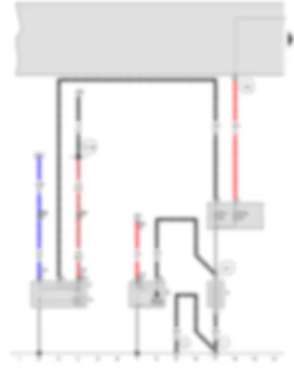
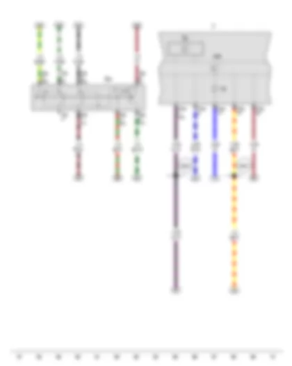
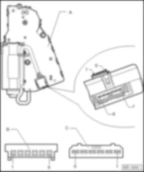
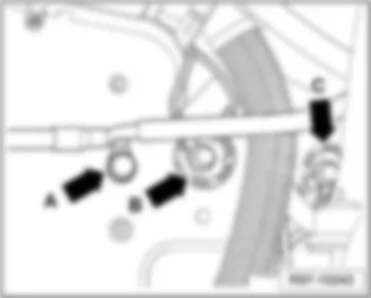
Wiring Diagram VW GOLF CITY 2010 - Battery - Starter - Alternator - Voltage regulator
| A | Battery |
| B | Starter |
| C | Alternator |
| C1 | Voltage regulator |
| J207 | Starter inhibitor relay |
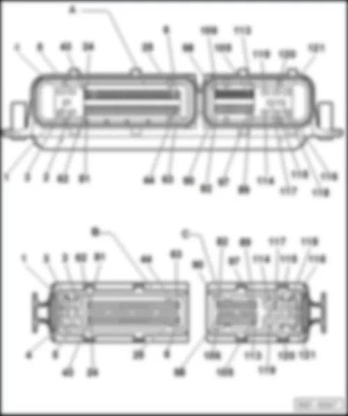
| J623 | Engine control unit |
| S176 | Fuse 4 (30), in battery fuse holder |
| S177 | Fuse 5 (30), in battery fuse holder |
| T1a | Single connector |
| T2h | 2-pin connector |
| T4a | 4-pin connector |
| T9d | 9-pin connector |
| 1 | Earth strap, battery - body |
| 2 | Earth strap, gearbox - body |
| 500 | Threaded connection 1 (30), on relay plate |
| 507 | Threaded connection (30), on battery fuse holder |
| D109 | Connection 7 in engine compartment wiring harness |
| * | Only models with manual gearbox |
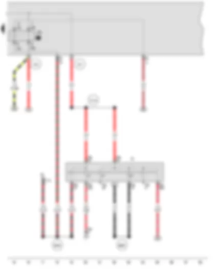
Wiring Diagram VW GOLF CITY 2010 - Ignition/starter switch - X-contact relief relay
| D | Ignition/starter switch |
| E1 | Light switch |
| J59 | X-contact relief relay |
| J207 | Starter inhibitor relay |
| T8a | 8-pin connector |
| T9d | 9-pin connector |
| T17a | 17-pin connector |
| 501 | Threaded connection 2 (30), on relay plate |
| 503 | Threaded connection (75x), on relay plate |
| B485 | Connection 21, in main wiring harness |
| B626 | Positive connection 2 (15), in main wiring harness |
| D144 | Positive connection 5 (30), in engine compartment wiring harness |
| * | Only models with manual gearbox |
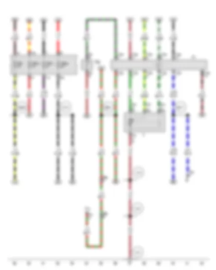
Wiring Diagram VW GOLF CITY 2010 - Intermittent wiper regulator - Automatic intermittent wash and wipe relay - Windscreen wiper motor
| E38 | Intermittent wiper regulator |
| J31 | Automatic intermittent wash and wipe relay |
| R | Radio |
| SA1 | Fuse 1 in fuse holder A |
| SA10 | Fuse 10 in fuse holder A |
| SA11 | Fuse 11 in fuse holder A |
| SA24 | Fuse 24 in fuse holder A |
| T4q | 4-pin connector |
| T4x | 4-pin connector |
| T5a | 5-pin connector |
| T5p | 5-pin connector |
| T6f | 6-pin connector |
| T8d | 8-pin connector |
| T18a | 18-pin connector |
| V | Windscreen wiper motor |
| V12 | Rear window wiper motor |
| 372 | Earth connection 7, in main wiring harness |
| 375 | Earth connection 10, in main wiring harness |
| 376 | Earth connection 11, in main wiring harness |
| B477 | Connection 13, in main wiring harness |
| B488 | Connection 24, in main wiring harness |
| B621 | Connection 1 (53c), in main wiring harness |
| D70 | Connection (53a), in engine compartment wiring harness |
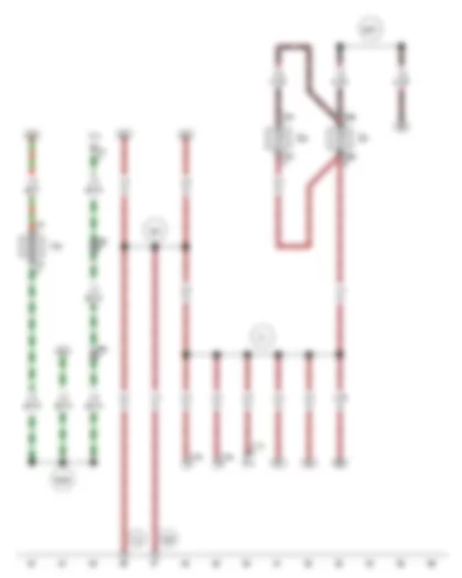
Wiring Diagram VW GOLF CITY 2010 - Windscreen and rear window washer pump - Left washer jet heater element - Right washer jet heater element
| E15 | Heated rear window switch |
| T2ca | 2-pin connector |
| T2cb | 2-pin connector |
| T2n | 2-pin connector |
| T4x | 4-pin connector |
| T5b | 5-pin connector |
| T5p | 5-pin connector |
| T16a | 16-pin connector |
| T17a | 17-pin connector |
| V12 | Rear window wiper motor |
| V59 | Windscreen and rear window washer pump |
| Z20 | Left washer jet heater element |
| Z21 | Right washer jet heater element |
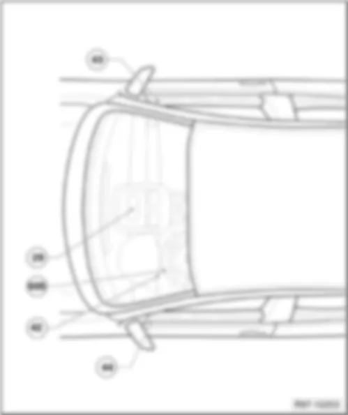
| 42 | Earth point, next to steering column |
| 369 | Earth connection 4, in main wiring harness |
| 371 | Earth connection 6, in main wiring harness |
| 605 | Earth point, on top end of steering column |
| B487 | Connection 23, in main wiring harness |
| B489 | Connection 25, in main wiring harness |
| * | Diagnostic connection |
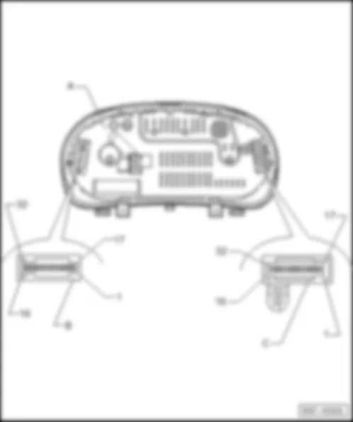
Wiring Diagram VW GOLF CITY 2010 - Intermittent wiper switch - Rev. counter - Control unit in dash panel insert - Dash panel insert - Alternator warning lamp
| E22 | Intermittent wiper switch |
| G5 | Rev. counter |
| J285 | Control unit in dash panel insert |
| K | Dash panel insert |
| K2 | Alternator warning lamp |
| T8e | 8-pin connector |
| T32a | 32-pin connector |
| B280 | Positive connection 4 (15a) in main wiring harness |
| B484 | Connection 20, in main wiring harness |
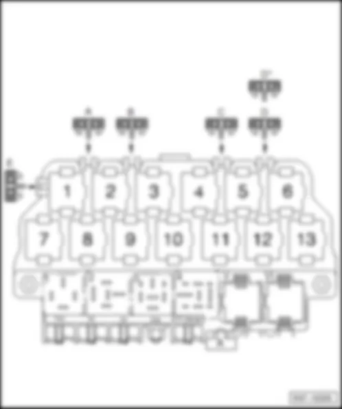
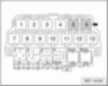
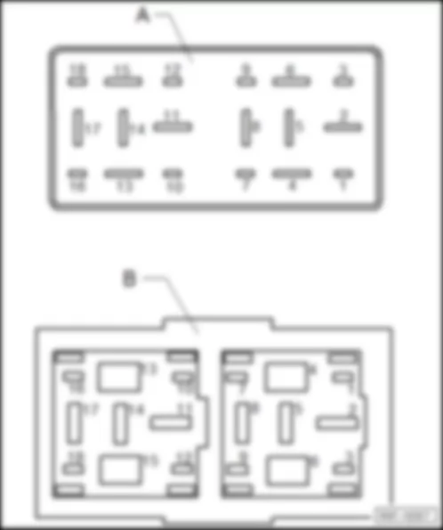
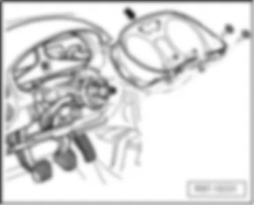
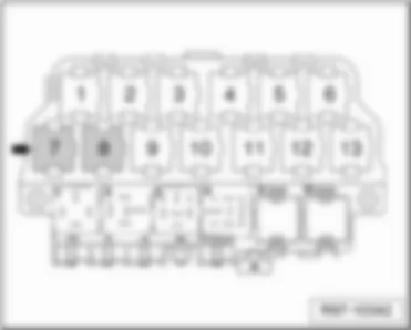
VW GOLF CITY 2010 Relay plate, behind left dash panel
| Relay plate, behind left dash panel |
| Relay description: |
| 1 - | vacant |
| q | Colour: - |
| 2 - | Cold start device relay -J41- |
| q | Colour: Black 1) |
| 3 - | Starter inhibitor relay -J207- |
| q | Colour: grey |
| 4 - | Fog light relay -J5- |
| q | Colour: grey |
| 5 - | Multifunction steering wheel control unit -J453- |
| q | Colour: black |
| 6 - | Multifunction steering wheel control unit -J453- |
| q | Colour: black |
| 7 - | Mirror memory control unit -J267- |
| q | Colour: black |
| 8 - | Mirror memory control unit -J267- |
| q | Colour: black |
| 9 - | vacant |
| q | Colour: - |
| 10 - | Secondary air pump relay -J299- |
| q | Colour: Black 2) |
| 11 - | Starter inhibitor and reversing light relay -J226- |
| q | Colour: Grey 3) |
| q |
| 11 - | Starter inhibitor relay 2 -J864- |
| q | Colour: Grey 4) |
| 12 - | Terminal 30 voltage supply relay -J317- |
| q | Colour: Grey 5) |
| 13 - | Ignition cut-off delay relay -J64- |
| q | Colour: Grey 6) |
| 13 - | Electric drive main relay -J437- |
| q | Colour: Grey 7) |
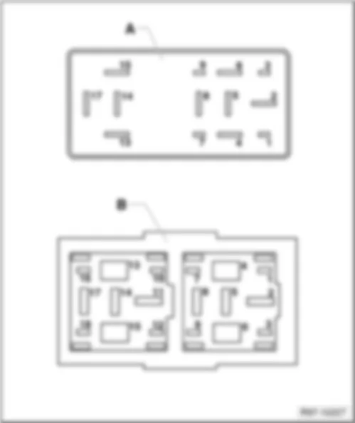
| Note
|
| Relay on additional support under relay plate |
| Relay description: |
| 1 - | Dual tone horn relay -J4- |
| q | Colour: grey |
| 2 - | X-contact relief relay -J59- |
| q | Colour: black |
| 3 - | vacant |
| q | Colour: - |
| 4 - | Glow plug relay -J52- |
| q | Colour: Black 1) |
| 4 - | Fuel pump relay -J17- |
| q | Colour: Black 2) |
| q | For vehicles with TotalFlex or petrol engines only |
| V - | Automatic intermittent wash and wipe relay -J31- |
| q | Colour: black |
| VI - | Automatic intermittent wash and wipe relay -J31- |
| q | Colour: black |
| Note
|

 Deutsch
 English
 English
 Español
 Français
 Nederlands

