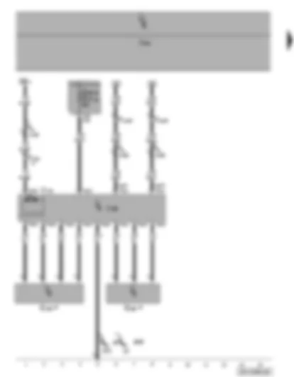
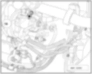
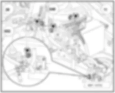
Wiring Diagram VW POLO 2004 - Steering hydraulics pump - power steering control unit - power steering sensor
| G250 | Power steering sensor |
| J500 | Power steering control unit |
| J519 | Onboard supply control unit |
| S164 | Fuse 3 (30), in fuse holder on battery |
| S177 | Fuse 5 (30), in fuse holder on battery |
| SB7 | Fuse 7 on fuse holder |
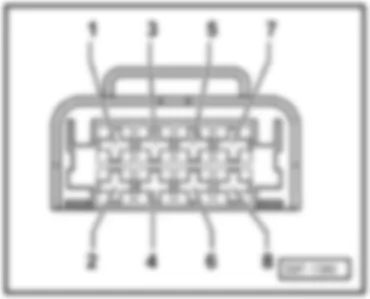
| T2a | 2-pin connector |
| T3s | 3-pin connector |
| T4r | 4-pin connector |
| T4s | 4-pin connector |
| T11a | 11-pin connector, white, on left of bulkhead |
| T11b | 11-pin connector, red, on left of bulkhead |
| V119 | Steering hydraulics pump |
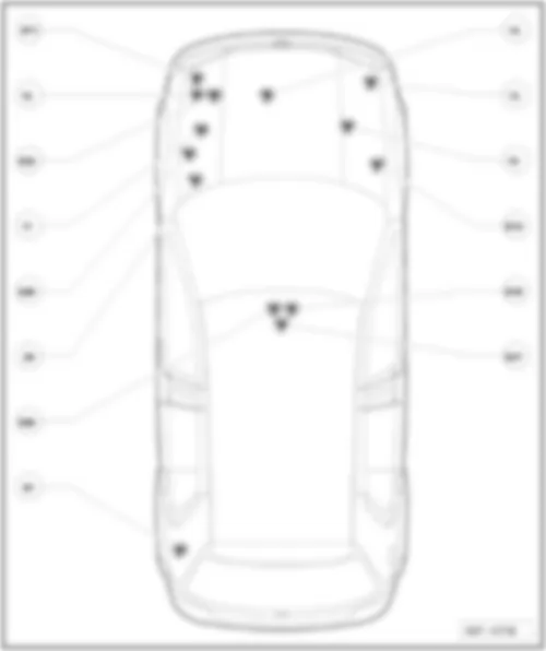
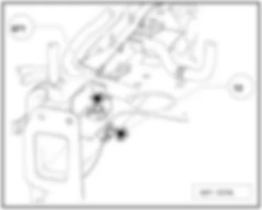
| 12 | Earth point, on left in engine compartment |
| 671 | Earth point 1, on front of left longitudinal member |
| A139 | Connection 3 (15), in dash panel wiring harness |
| D159 | Connection (high bus), in engine compartment wiring harness |
| D160 | Connection (low bus), in engine compartment wiring harness |
| * | depends on equipment |
| # | up to November 2006 |
| ## | from November 2006 |
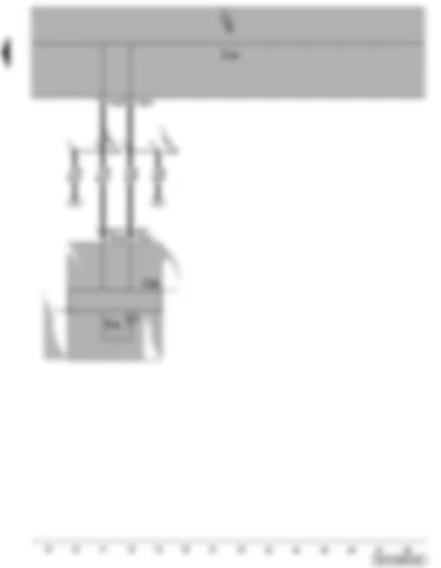
Wiring Diagram VW POLO 2004 - Display control unit in dash panel insert - servotronic warning lamp
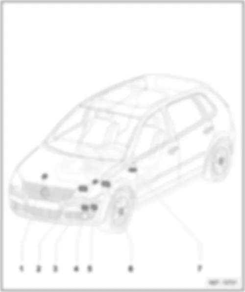
VW POLO 2004 Overview of all control units
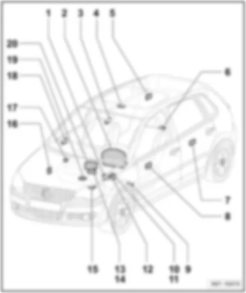
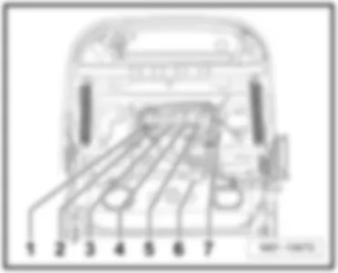
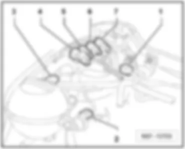
Overview of all control units | | | | 1 - | ABS control unit with EDL -J104- |
| 2 - | Automatic gearbox control unit -J217- |
| 3 - | Glow plug activation control unit -J370- |
| 3 - | Automatic glow period control unit -J179- |
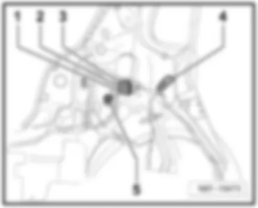
| 4 - | Power steering control unit -J500- |
| 5 - | Radiator fan control unit -J293- |
| 6 - | Engine control units -J248- , -J623- , -J361- , -J220- , -J687- , -J537- |
| 7 - | NOx sensor control unit -J583- |
| Polo | Fitting Locations | No. 805 / 2 |
|
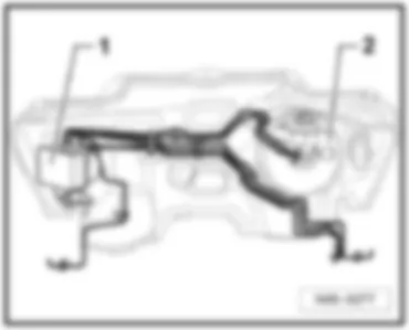
| On right of bulkhead in engine compartment ⇒ -1- | | | |
| Polo | Fitting Locations | No. 805 / 3 |
|
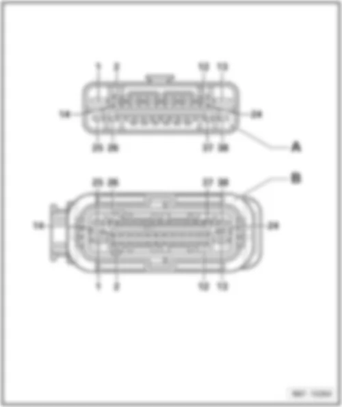
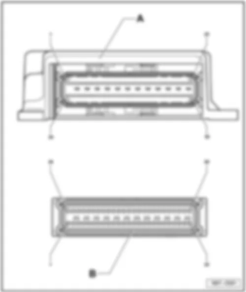
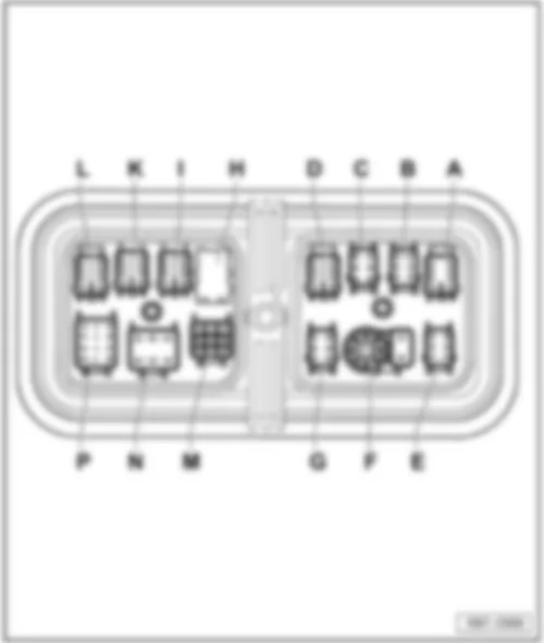
| Connectors for ABS control unit -J104- |
| Polo | Fitting Locations | No. 805 / 4 |
|
| Connectors for ABS control unit -J104- |
| Polo | Fitting Locations | No. 805 / 5 |
|
VW POLO 2004 Glow plug activation control unit -J370- / automatic glow period control unit -J179- |
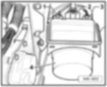
| front left in engine compartment | | | |
| Polo | Fitting Locations | No. 805 / 6 |
|
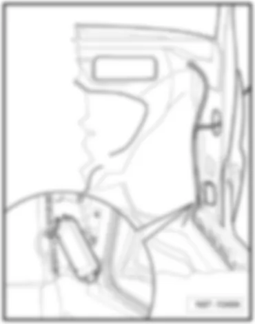
VW POLO 2004 Automatic gearbox control unit -J217-Automatic gearbox control unit -J217- |
| in engine compartment before battery | | | |
| Polo | Fitting Locations | No. 805 / 7 |
|
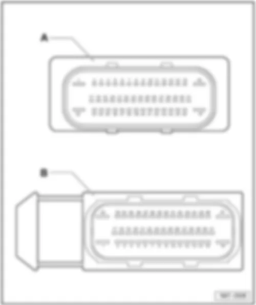
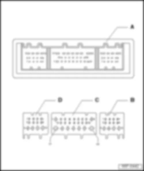
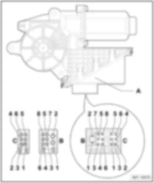
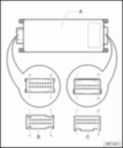
| Connectors for automatic gearbox control unit -J217- |
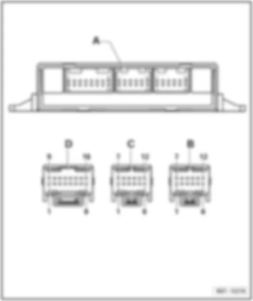
| A - | Automatic gearbox control unit -J217- |
| Polo | Fitting Locations | No. 805 / 8 |
|
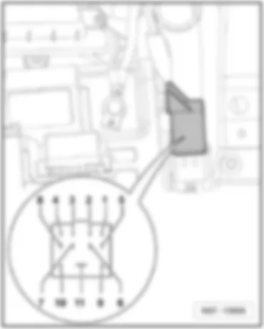
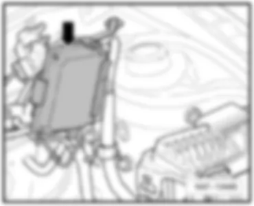
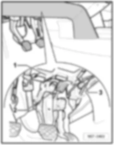
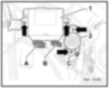
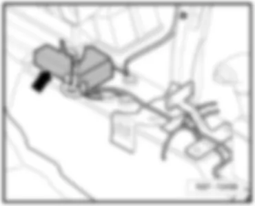
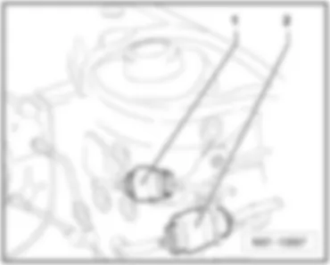
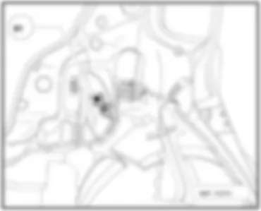
VW POLO 2004 Power steering control unit -J500-Power steering control unit -J500- |
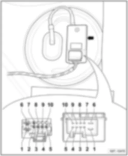
| In engine compartment, on front of left longitudinal member | | 3 - | Connector, depends on equipment -T3s- or -T4s- | | | |
| Polo | Fitting Locations | No. 805 / 9 |
|
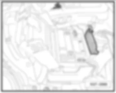
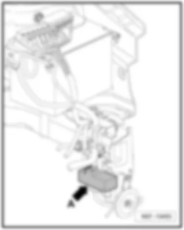
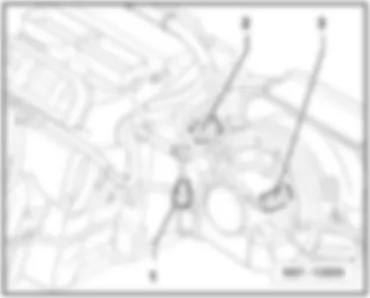
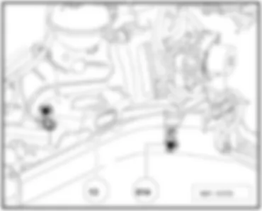
VW POLO 2004 Radiator fan control unit -J293-Radiator fan control unit -J293- |
| Front left in engine compartment ⇒ -arrow A- | | | |
| Polo | Fitting Locations | No. 805 / 10 |
|
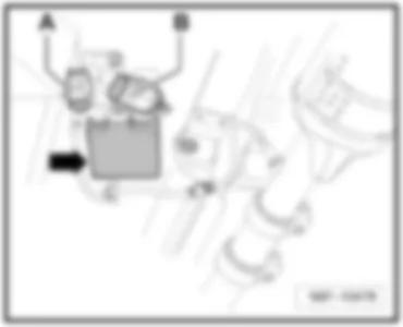
VW POLO 2004 NOx sensor control unit -J583-NOx sensor control unit -J583- |
| Under vehicle, near catalytic converter ⇒ -arrow- | | A - | 10-pin connector, black (T10) | | B - | 14-pin connector, black (T14x) | | | |
| Polo | Fitting Locations | No. 805 / 11 |
|
VW POLO 2004 Engine control unit - J...Engine control unit - J... |
| On left of bulkhead ⇒ -arrow- | | | |
| Polo | Fitting Locations | No. 805 / 12 |
|
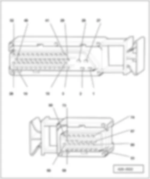
| Engine control unit - J... | Note: | Note: see respective current flow diagram for engine control unit. | | | |
Note:
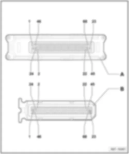
| t | Note Connector T80 comprises a 52-pin and a 28-pin connector. |
| t | * Depending on equipment |
| t | Connector 121, see 207/12 |
| t | Connector T94 and T60, see 207/13 |
| Polo | Fitting Locations | No. 805 / 13 |
|
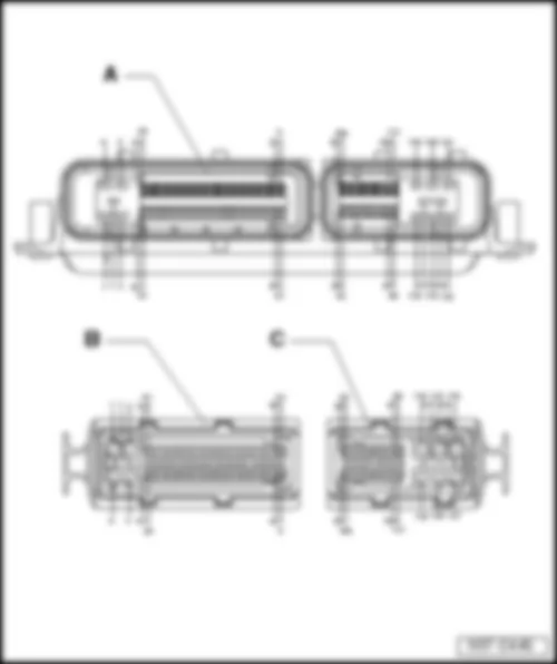
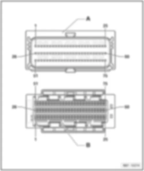
| Engine control unit - J... | Note: | Note: see respective current flow diagram for engine control unit. | | | |
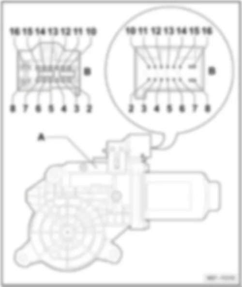
| A - | Engine control unit, 121-pin |
Note:
| Note Connector T121 comprises an 81-pin connector and a 40-pin connector. |
| Polo | Fitting Locations | No. 805 / 14 |
|
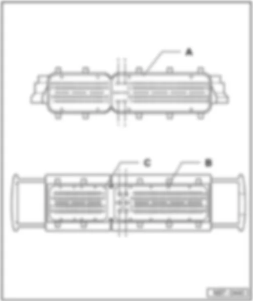
| Engine control unit - J... | Note: | Note: see respective current flow diagram for engine control unit. | | | |
| A - | Engine control unit, 154-pin |
Note:
| Note Connector T154 comprises a 94-pin and a 60-pin connector. |

 Deutsch
 English
 English
 Español
 Français
 Nederlands

