AUTOMOTIVE ELECTRICIANS PORTAL

VW AMAROK 2014 — Auxiliary lights, (2Y1),(E5W) . Wiring diagrams, Pin Connector, Location

Wiring Diagram VW AMAROK 2014 - Steering column combination switch - Headlight main beam relay - Fuse 5 on fuse holder B


Wiring Diagram  VW AMAROK 2014 - Steering column combination switch - Headlight main beam relay - Fuse 5 on fuse holder B https://portal-diagnostov.com/license.html
https://portal-diagnostov.com/license.html Automotive Electricians Portal FZCO Automotive Electricians Portal FZCO
Download PDF file
E595 Steering column combination switch
J12 Headlight main beam relay
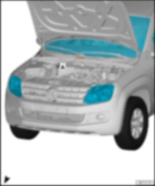
M67 Left additional main beam bulb
M68 Right additional main beam bulb
M113 Centre left additional main beam bulb
M114 Centre right additional main beam bulb
SB5 Fuse 5 on fuse holder B
T2cm 2-pin connector, black
T41 41-pin connector, grey
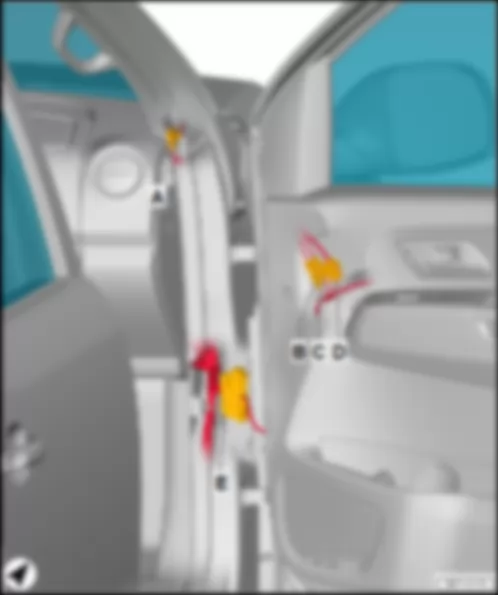
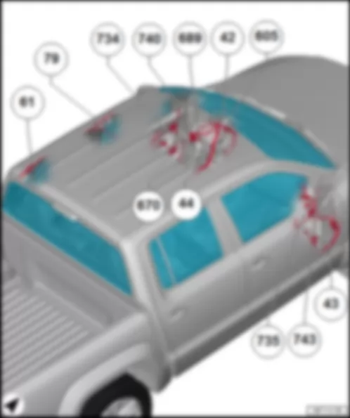
  42 Earth point, next to steering column
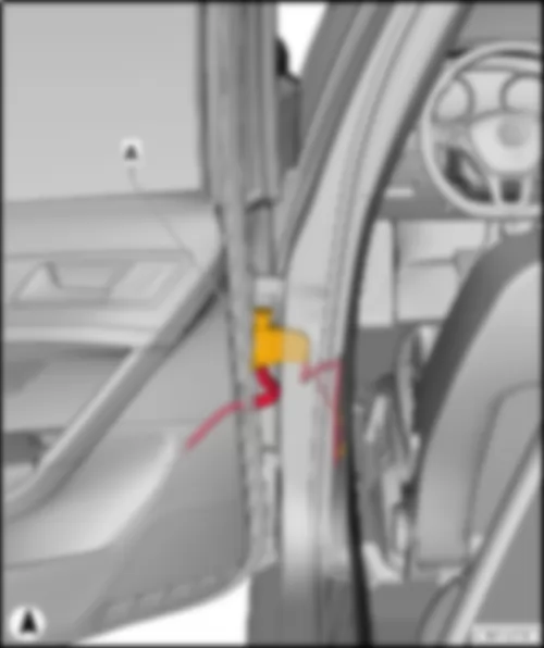
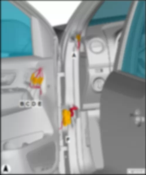
  44 Earth point, lower part of left A-pillar
  61 Earth point, left C-pillar
  79 Earth point on left B-pillar
  119 Earth connection 1, in headlight wiring harness
  366 Earth connection 1, in main wiring harness
  370 Earth connection 5, in main wiring harness
  371 Earth connection 6, in main wiring harness
  B475 Connection 11, in main wiring harness
  C12 Positive connection 1, in headlight wiring harness
*Only models with double cab
*2see applicable current flow diagram for exterior lighting
*3Only models with single cab


VW AMAROK 2014


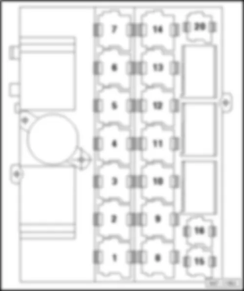
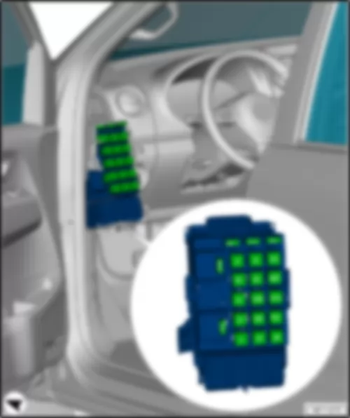
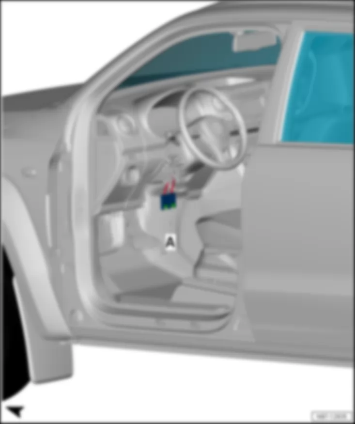
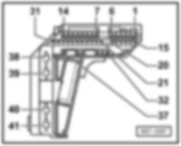
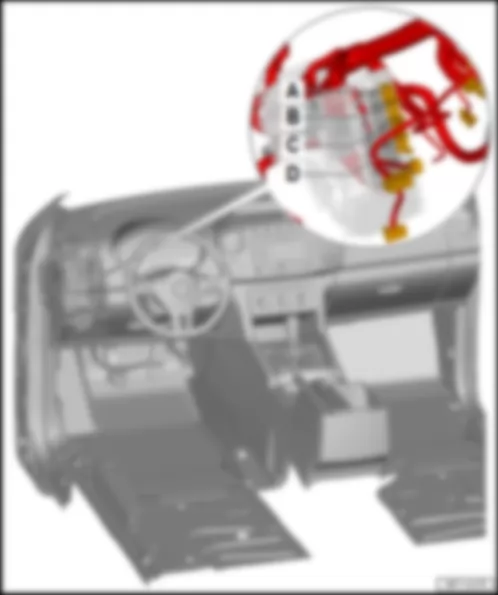
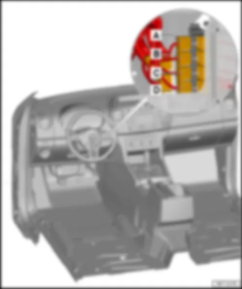
VW AMAROK 2014 Relay carrier under the dash panel on left (left-hand drive), up to May 2012

Relay carrier under the dash panel on left (left-hand drive), up to May 2012
Relay assignment
VW AMAROK 2014 Relay carrier under the dash panel on left (left-hand drive), up to May 2012 https://portal-diagnostov.com/license.html
https://portal-diagnostov.com/license.html Automotive Electricians Portal FZCO Automotive Electricians Portal FZCO
Получить доступ ко всем электросхемам автомобиляDownload PDF file
1 -  Auxiliary coolant heater relay -J493- (404)
2 -  Voltage supply relay 1 -J701- (53)
3a -  Fuel pump relay -J17- (404)
3b -  Terminal 30 voltage supply relay -J317- (404)
4 -  Starter motor relay -J53- (53) 3)
5 -  Not assigned
6 -  Not assigned
7 -  Starter motor relay -J53- (53) 4)
8 -  Coolant pump relay -J235- (404)
9 -  Voltage supply relay 2 -J710- (53)
10 -  Terminal 15 voltage supply relay -J329- (100)
11 -  Main relay -J271- (643) 2)
12 -  Starter relay 2 -J907- (433) 4)
13 -  Starter relay 1 -J906- (643) 4)
14 -  Headlight relay -J25- (53) 4)
15 -  Current supply relay -J16- (100)
16 -  Terminal 58b relief relay -J374- (449)
20 -  Main relay -J271- (643) 1)

  Note:
t  1) Valid until July 2010
t  2) Valid from July 2010
t  3) Only models with no start/stop system
t  4) Only models with start/stop system
–  Back to overview → Chapter


VW AMAROK 2014 Relay carrier under the dash panel on left (left-hand drive), from June 2012

Relay carrier under the dash panel on left (left-hand drive), from June 2012
Relay assignment
VW AMAROK 2014 Relay carrier under the dash panel on left (left-hand drive), from June 2012 https://portal-diagnostov.com/license.html
https://portal-diagnostov.com/license.html Automotive Electricians Portal FZCO Automotive Electricians Portal FZCO
Получить доступ ко всем электросхемам автомобиляDownload PDF file
I a -  Coolant pump relay -J235- (646) 1)
I b -  Auxiliary coolant heater relay -J493- (646)
II -  Main relay -J271- (645)
III a -  Terminal 30 voltage supply relay -J317- (646) 1)
III b -  Not assigned
IV -  Not assigned
V -  Not assigned
VI -  Voltage supply relay 2 -J710- (645)
VII -  Terminal 15 voltage supply relay -J329- (644)
VIII -  Starter motor relay -J53- (645)
IX -  Headlight relay -J25- (645)
X a -  Electric fuel pump 2 relay -J49- (646)
X b -  Fresh air blower relay -J13- (646)
XI -  Current supply relay -J16- (644)
XII -  Not assigned
XIII a -  Fuel pump relay -J17- (646) 1)
XIII a -  Terminal 30 voltage supply relay -J317- (646) 2)
XIII b -  Terminal 58b relief relay -J374- (646)
XIV -  Starter relay 2 -J907- (507) 3)
XV -  Starter relay 1 -J906- (645) 3)
XVI -  Not assigned
XVII -  Not assigned
XVIII -  Not assigned
XIX -  Not assigned
XX -  Not assigned

  Note:
t  1) Only models with petrol engine
t  2) Only models with diesel engine
t  3) Only models with start/stop system
–  Back to overview → Chapter


VW AMAROK 2014 Relay carrier under the dash panel on left (left-hand drive), from January 2013

Relay carrier under the dash panel on left (left-hand drive), from January 2013
Relay assignment
VW AMAROK 2014 Relay carrier under the dash panel on left (left-hand drive), from January 2013 https://portal-diagnostov.com/license.html
https://portal-diagnostov.com/license.html Automotive Electricians Portal FZCO Automotive Electricians Portal FZCO
Получить доступ ко всем электросхемам автомобиляDownload PDF file
I a -  Coolant pump relay -J235- (646) 1)
I b -  Auxiliary coolant heater relay -J493- (646)
II -  Main relay -J271- (645)
III -  Not assigned
IV -  Not assigned
V -  Not assigned
VI -  Voltage supply relay 2 -J710- (644)
VII a -  Electric fuel pump 2 relay -J49- (646)
VII b -  Fresh air blower relay -J13- (646)
VIII -  Starter motor relay -J53- (645)
IX -  Fresh air blower isolation relay -J487- (645)
X -  Terminal 15 voltage supply relay -J329- (644)
XI a -  Headlight relay -J25- (645)
XI b -  Terminal 30 voltage supply relay -J317- (646) 1)
XII -  Current supply relay -J16- (644)
XIII a -  Not assigned
XIII b -  Relay for headlight main beam -J12- (646)
XIV -  Starter relay 2 -J907- (507) 3)
XV -  Starter relay 1 -J906- (645) 3)
XVI -  Not assigned
XVII -  Not assigned
XVIII -  Not assigned
XIX -  Fuel pump relay -J17- (646) 1)
XIX -  Terminal 30 voltage supply relay -J317- (646) 2)
XX -  Terminal 58b relief relay -J374- (646)

  Note:
t  1) Only models with petrol engine
t  2) Only models with diesel engine
t  3) Only models with start/stop system
–  Back to overview → Chapter


VW AMAROK 2014 Relay carrier under the dash panel on left (left-hand drive), from July 2013

Relay carrier under the dash panel on left (left-hand drive), from July 2013
Relay assignment
  Note:
t  only models with model key S1A/S1B up to April 2014
t  only models with model key 2HA/SHB up to July 2014
   
VW AMAROK 2014 Relay carrier under the dash panel on left (left-hand drive), from July 2013 https://portal-diagnostov.com/license.html
https://portal-diagnostov.com/license.html Automotive Electricians Portal FZCO Automotive Electricians Portal FZCO
Получить доступ ко всем электросхемам автомобиляDownload PDF file
I a -  Coolant pump relay -J235- (646) 1)
I a -  Terminal 30 voltage supply relay -J317- (646) 2)
I b -  Auxiliary coolant heater relay -J493- (646)
II -  Main relay -J271- (645)
III -  Not assigned
IV -  Not assigned
V -  Not assigned
VI -  Voltage supply relay 2 -J710- (644)
VII a -  Fresh air blower relay -J13- (646)
VII b -  Electric fuel pump 2 relay -J49- (646)
VIII -  Starter motor relay -J53- (645)
IX -  Fresh air blower isolation relay -J487- (645)
X -  Terminal 15 voltage supply relay -J329- (644)
XI a -  Headlight relay -J25- (646)
XI b -  Terminal 30 voltage supply relay -J317- (646) 1)
XII -  Current supply relay -J16- (644)
XIII a -  Not assigned
XIII b -  Relay for headlight main beam -J12- (646)
XIV -  Starter relay 2 -J907- (507) 3)
XV -  Starter relay 1 -J906- (645) 3)
XVI -  Not assigned
XVII -  Not assigned
XVIII -  Not assigned
XIX -  Fuel pump relay -J17- (646)
XX -  Terminal 58b relief relay -J374- (646)

  Note:
t  1) Only models with petrol engine
t  2) Only models with diesel engine
t  3) Only models with start/stop system
–  Back to overview → Chapter


VW AMAROK 2014 Relay carrier under the dash panel on left (left-hand drive), from April 2014

Relay carrier under the dash panel on left (left-hand drive), from April 2014
Relay assignment
  Note:
t  only models with model key S1A/S1B from April 2014
t  only models with model key 2HA/SHB from July 2014
   
VW AMAROK 2014 Relay carrier under the dash panel on left (left-hand drive), from April 2014 https://portal-diagnostov.com/license.html
https://portal-diagnostov.com/license.html Automotive Electricians Portal FZCO Automotive Electricians Portal FZCO
Получить доступ ко всем электросхемам автомобиляDownload PDF file
I -  Fresh air blower isolation relay -J487- (645) 6)
II -  Not assigned
III -  Not assigned
IV -  Not assigned
V -  Not assigned
VI -  Starter relay 2 -J907- (507) 3)
VII -  Starter relay 1 -J906- (645) 3)
VIII -  Starter motor relay -J53- (645) 3), 4), 6) or 4), 7)
IX a -  Auxiliary coolant heater relay -J493- (646)
IX b -  Coolant pump relay -J235- (646) 1)
IX b -  Terminal 30 voltage supply relay -J317- (646) 2)
X a  -  Alarm system relay 1 -J460- (646) 5)
X b -  Relay for headlight main beam -J12- (646)
XI -  Main relay -J271- (645)
XII -  Terminal 15 voltage supply relay -J329- (644)
XIII -  Current supply relay -J16- (644)
XIV -  Voltage supply relay 2 -J710- (644)
XV a -  Electric fuel pump 2 relay -J49- (646)
XV b -  Terminal 30 voltage supply relay -J317- (646) 1)
XV b -  Fresh air blower relay -J13- (646) 6)
XVI -  Not assigned
XVII -  Not assigned
XVIII -  Not assigned
XIX -  Fuel pump relay -J17- (646)
XX -  Terminal 58b relief relay -J374- (646)
XX -  Headlight relay -J25- (646)

  Note:
t  1) Only models with petrol engine
t  2) Only models with diesel engine
t  3) Only models with start/stop system
t  4) Only models with no start/stop system
t  5) Only models with anti-theft alarm system and alarm system horn -H18-
t  6) Valid until January 2015
t  7) Valid from January 2015
–  Back to overview → Chapter


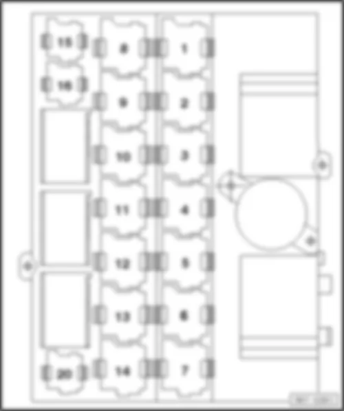
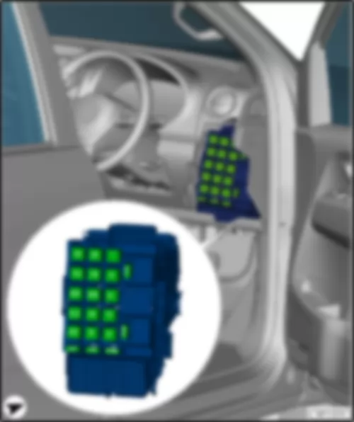
VW AMAROK 2014 Relay carrier under the dash panel on right (right-hand drive), up to May 2012

Relay carrier under the dash panel on right (right-hand drive), up to May 2012
Relay assignment
VW AMAROK 2014 Relay carrier under the dash panel on right (right-hand drive), up to May 2012 https://portal-diagnostov.com/license.html
https://portal-diagnostov.com/license.html Automotive Electricians Portal FZCO Automotive Electricians Portal FZCO
Получить доступ ко всем электросхемам автомобиляDownload PDF file
1 -  Auxiliary coolant heater relay -J493- (404)
2 -  Starter motor relay -J53- (53) 6)
3 -  Not assigned
4 -  Not assigned
5 -  Main relay -J271- (643) 2), 3)
5 -  Starter relay 2 -J907- (433) 6)
6 -  Voltage supply relay 2 -J710- (53)
7 -  Terminal 15 voltage supply relay -J329- (100)
8 -  Coolant pump relay -J235- (404)
9 -  Headlight relay -J25- (53) 6)
10 -  Starter relay 1 -J906- (643) 6)
11 -  Current supply relay -J16- (100) 4)
12 -  Voltage supply relay 1 -J701- (53)
13 -  Starter motor relay -J53- (53) 5)
14a -  Fuel pump relay -J17- (404)
14b -  Terminal 30 voltage supply relay -J317- (404)
15 -  Current supply relay -J16- (100) 3)
16 -  Terminal 58b relief relay -J374- (449)
20 -  Main relay -J271- (643) 1), 4)

  Note:
t  1) Valid until July 2010
t  2) Valid from July 2010
t  3) Valid until January 2011
t  4) Valid from February 2011
t  5) Only models with no start/stop system
t  6) Only models with start/stop system
–  Back to overview → Chapter


VW AMAROK 2014 Relay carrier under the dash panel on right (right-hand drive), from June 2012

Relay carrier under the dash panel on right (right-hand drive), from June 2012
Relay assignment
VW AMAROK 2014 Relay carrier under the dash panel on right (right-hand drive), from June 2012 https://portal-diagnostov.com/license.html
https://portal-diagnostov.com/license.html Automotive Electricians Portal FZCO Automotive Electricians Portal FZCO
Получить доступ ко всем электросхемам автомобиляDownload PDF file
I -  Not assigned
II -  Not assigned
III -  Terminal 30 voltage supply relay -J317- (646) 1)
IV -  Voltage supply relay 2 -J710- (645)
V -  Terminal 15 voltage supply relay -J329- (644)
VI -  Not assigned
VII a -  Electric fuel pump 2 relay -J49- (646)
VII b -  Fresh air blower relay -J13- (646)
VIII -  Not assigned
IX -  Starter motor relay -J53- (645)
X a -  Fuel pump relay -J17- (646)
X a -  Terminal 30 voltage supply relay -J317- (646) 2)
X b -  Not assigned
XI -  Headlight relay -J25- (645)
XII -  Starter relay 1 -J906- (645) 3)
XIII -  Current supply relay -J16- (644)
XIV -  Starter relay 2 -J907- (507) 3)
XV -  Main relay -J271- (645)
XVI -  Not assigned
XVII -  Not assigned
XVIII -  Auxiliary coolant heater relay -J493- (646)
XIX -  Coolant pump relay -J235- (646)
XX -  Terminal 58b relief relay -J374- (646)

  Note:
t  1) Only models with petrol engine
t  2) Only models with diesel engine
t  3) Only models with start/stop system
–  Back to overview → Chapter


VW AMAROK 2014 Relay carrier under the dash panel on right (right-hand drive), from January 2013

Relay carrier under the dash panel on right (right-hand drive), from January 2013
Relay assignment
VW AMAROK 2014 Relay carrier under the dash panel on right (right-hand drive), from January 2013 https://portal-diagnostov.com/license.html
https://portal-diagnostov.com/license.html Automotive Electricians Portal FZCO Automotive Electricians Portal FZCO
Получить доступ ко всем электросхемам автомобиляDownload PDF file
I -  Not assigned
II -  Not assigned
III -  Not assigned
IV -  Terminal 15 voltage supply relay -J329- (644)
V -  Voltage supply relay 2 -J710- (644)
VI a -  Relay for headlight main beam -J12- (646)
VI b -  Not assigned
VII a -  Electric fuel pump 2 relay -J49- (646)
VII b -  Fresh air blower relay -J13- (646)
VIII a -  Headlight relay -J25- (646)
VIII b -  Terminal 30 voltage supply relay -J317- (646) 1)
IX -  Starter motor relay -J53- (645)
X a -  Fuel pump relay -J17- (646)
X a -  Terminal 30 voltage supply relay -J317- (646) 2)
X b -  Coolant pump relay -J235- (646) 1)
XI -  Fresh air blower isolation relay -J487- (645)
XII -  Starter relay 1 -J906- (645) 3)
XIII -  Current supply relay -J16- (644)
XIV -  Starter relay 2 -J907- (507) 3)
XV -  Main relay -J271- (645)
XVI -  Not assigned
XVII -  Not assigned
XVIII -  Not assigned
XIX -  Auxiliary coolant heater relay -J493- (646)
XX -  Terminal 58b relief relay -J374- (646)

  Note:
t  1) Only models with petrol engine
t  2) Only models with diesel engine
t  3) Only models with start/stop system
–  Back to overview → Chapter


VW AMAROK 2014 Relay carrier under the dash panel on right (right-hand drive), from July 2013

Relay carrier under the dash panel on right (right-hand drive), from July 2013
  Note:
t  only models with model key S1A/S1B up to April 2014
t  only models with model key 2HA/SHB up to July 2014
   
Relay assignment
VW AMAROK 2014 Relay carrier under the dash panel on right (right-hand drive), from July 2013 https://portal-diagnostov.com/license.html
https://portal-diagnostov.com/license.html Automotive Electricians Portal FZCO Automotive Electricians Portal FZCO
Получить доступ ко всем электросхемам автомобиляDownload PDF file
I -  Not assigned
II -  Not assigned
III -  Not assigned
IV -  Terminal 15 voltage supply relay -J329- (644)
V -  Voltage supply relay 2 -J710- (644)
VI a -  Relay for headlight main beam -J12- (646)
VI b -  Not assigned
VII -  Starter relay 1 -J906- (645) 3)
VIII a -  Headlight relay -J25- (646)
VIII b -  Terminal 30 voltage supply relay -J317- (646) 1)
IX -  Starter motor relay -J53- (645)
X a -  Fuel pump relay -J17- (646)
X b -  Coolant pump relay -J235- (646) 1)
X b -  Terminal 30 voltage supply relay -J317- (646) 2)
XI -  Fresh air blower isolation relay -J487- (645)
XII a -  Electric fuel pump 2 relay -J49- (646)
XII b -  Fresh air blower relay -J13- (646)
XIII -  Current supply relay -J16- (644)
XIV -  Starter relay 2 -J907- (507) 3)
XV -  Main relay -J271- (645)
XVI -  Not assigned
XVII -  Not assigned
XVIII -  Not assigned
XIX -  Auxiliary coolant heater relay -J493- (646)
XX -  Terminal 58b relief relay -J374- (646)

  Note:
t  1) Only models with petrol engine
t  2) Only models with diesel engine
t  3) Only models with start/stop system
–  Back to overview → Chapter


VW AMAROK 2014 Relay carrier under the dash panel on right (right-hand drive), from April 2014

Relay carrier under the dash panel on right (right-hand drive), from April 2014
  Note:
t  only models with model key S1A/S1B from April 2014
t  only models with model key 2HA/SHB from July 2014
   
Relay assignment
VW AMAROK 2014 Relay carrier under the dash panel on right (right-hand drive), from April 2014 https://portal-diagnostov.com/license.html
https://portal-diagnostov.com/license.html Automotive Electricians Portal FZCO Automotive Electricians Portal FZCO
Получить доступ ко всем электросхемам автомобиляDownload PDF file
I -  Not assigned
II -  Not assigned
III -  Not assigned
IV -  Not assigned
V -  Fresh air blower isolation relay -J487- (645) 6)
VI a -  Auxiliary coolant heater relay -J493- (646)
VI b -  Coolant pump relay -J235- (646) 1)
VI b -  Terminal 30 voltage supply relay -J317- (646) 2)
VII -  Starter relay 1 -J906- (645) 3)
VIII -  Starter motor relay -J53- (645) 3), 4), 6) or 4), 7)
IX -  Starter relay 2 -J907- (507) 3)
X a -  Alarm system relay 1 -J460- (646) 5)
X b -  Relay for headlight main beam -J12- (646)
XI -  Main relay -J271- (645)
XII -  Terminal 15 voltage supply relay -J329- (644)
XIII -  Current supply relay -J16- (644)
XIV -  Voltage supply relay 2 -J710- (644)
XV a -  Electric fuel pump 2 relay -J49- (646)
XV b -  Terminal 30 voltage supply relay -J317- (646) 1)
XV b -  Fresh air blower relay -J13- (646) 6)
XVI -  Not assigned
XVII -  Not assigned
XVIII -  Not assigned
XIX -  Fuel pump relay -J17- (646)
XX -  Headlight relay -J25- (646)
XX -  Terminal 58b relief relay -J374- (646)

  Note:
t  1) Only models with petrol engine
t  2) Only models with diesel engine
t  3) Only models with start/stop system
t  4) Only models with no start/stop system
t  5) Only models with anti-theft alarm system and alarm system horn -H18-
t  6) Valid until January 2015
t  7) Valid from January 2015
–  Back to overview → Chapter


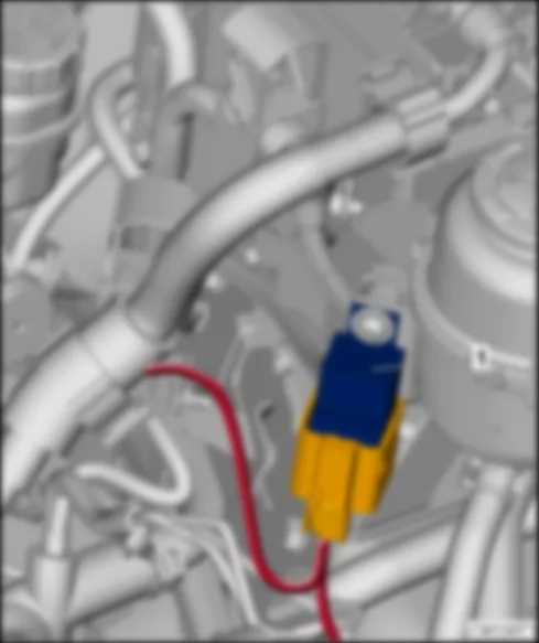
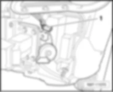
VW AMAROK 2014 Relay holder for engine dust kit, on steering fluid container

Relay holder for engine dust kit, on steering fluid container
Relay location
VW AMAROK 2014 Relay holder for engine dust kit, on steering fluid container https://portal-diagnostov.com/license.html
https://portal-diagnostov.com/license.html Automotive Electricians Portal FZCO Automotive Electricians Portal FZCO
Получить доступ ко всем электросхемам автомобиляDownload PDF file
1 -  Blower relay -J323-

–  Back to overview → Chapter


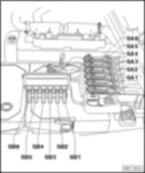
VW AMAROK 2014 Fuse holder A SA

Fuse holder A -SA-
Fitting location
t  Position of fuses on fuse holder, on the battery
   
Fuse colours
VW AMAROK 2014 Fuse holder A SA https://portal-diagnostov.com/license.html
https://portal-diagnostov.com/license.html Automotive Electricians Portal FZCO Automotive Electricians Portal FZCO
Получить доступ ко всем электросхемам автомобиляDownload PDF file
200 A -  purple
150 A -  grey
125 A -  pink
100 A -  blue
80 A -  white
70 A -  brown
60 A -  yellow
50 A -  red
40 A -  green
30 A -  orange

Fuse assignment, from November 2009
   
No. Current Flow Diagram designation Nominal value Function/component
1   Fuse 1 on fuse holder A -SA1- 175A -
Alternator -C-
2   Fuse 2 on fuse holder A -SA2- 175A -
-
-
-
-
-
-
-
-
-
-
-
-
-
-
-
-
-
-
-
-
Current supply relay -J16-
Fuel pump relay -J17-1)
Starter motor relay -J53-
Main relay -J271-
Terminal 15 voltage supply relay -J329-
Terminal 58b relief relay -J374-3)
Voltage supply relay 1 -J701-
Voltage supply relay 2 -J710-
Fuse 3 on fuse holder C -SC3-
Fuse 4 on fuse holder C -SC4-
Fuse 8 on fuse holder C -SC8-
Fuse 11 on fuse holder C -SC11-
Fuse 15 on fuse holder C -SC15-
Fuse 19 on fuse holder C -SC19- to
Fuse 24 on fuse holder C -SC24-
Fuse 43 on fuse holder C -SC43- to
Fuse 51 on fuse holder C -SC51-
Fuse 62 on fuse holder C -SC62- to
Fuse 64 on fuse holder C -SC64-
Fuse 66 on fuse holder C -SC66-
Fuse 67 on fuse holder C -SC67-
3   Fuse 3 on fuse holder A -SA3- 50A -
Interface for external use (T6h/4)
4   Fuse 4 on fuse holder A -SA4- 80/110A -
-
Radiator fan control unit -J293-
Radiator fan -V7-
5   Fuse 5 on fuse holder A -SA5- 50A -
Automatic glow period control unit -J179-2)
6   Fuse 6 on fuse holder A -SA6- 80A -
-
Fuse 39 on fuse holder C -SC39- to
Fuse 41 on fuse holder C -SC41-

  Note:
t  1) Only models with petrol engine
t  2) Only models with diesel engine
t  3) Only models with connector, 17-pin -T17- on light switch -E1- (external lighting 8K0/8K1)
–  Back to overview → Chapter
Fuse assignment, from May 2011
   
No. Current Flow Diagram designation Nominal value Function/component
1 - Fuse 1 on fuse holder A -SA1- 175A -
Alternator -C-
2 - Fuse 2 on fuse holder A -SA2- 175A -
-
-
-
-
-
-
-
-
-
-
-
-
-
-
-
-
-
-
-
-
-
-
Fuse 1 on fuse holder C -SC1- to
Fuse 15 on fuse holder C -SC15-
Fuse 16 on fuse holder C -SC16-1)
Fuse 19 on fuse holder C -SC19- to
Fuse 25 on fuse holder C -SC25-
Fuse 28 on fuse holder C -SC28-1) to
Fuse 30 on fuse holder C -SC30-1)
Fuse 33 on fuse holder C -SC33-2)
Fuse 34 on fuse holder C -SC34-2)
Fuse 35 on fuse holder C -SC35-
Fuse 36 on fuse holder C -SC36-
Fuse 37 on fuse holder C -SC37-2)
Fuse 38 on fuse holder C -SC38-
Fuse 42 on fuse holder C -SC42- to
Fuse 52 on fuse holder C -SC52-
Fuse 53 on fuse holder C -SC53-1)
Fuse 54 on fuse holder C -SC54-
Fuse 55 on fuse holder C -SC55-1)
Fuse 56 on fuse holder C -SC56-2)
Fuse 57 on fuse holder C -SC57-
Fuse 59 on fuse holder C -SC59-
Fuse 62 on fuse holder C -SC62- to
Fuse 72 on fuse holder C -SC72-
3 - Fuse 3 on fuse holder A -SA3- 40A -
Interface for external use
4 - Fuse 4 on fuse holder A -SA4- 80/110A -
-
Radiator fan control unit -J293-
Radiator fan -V7-
5 - Fuse 5 on fuse holder A -SA5- 50A -
Automatic glow period control unit -J179-
6 - Fuse 6 on fuse holder A -SA6- 80A -
-
-
Fuse 39 on fuse holder C -SC39-
Fuse 40 on fuse holder C -SC40-
Fuse 41 on fuse holder C -SC41-

  Note:
t  1) Only models with start/stop system (7L6)
t  2) Only models with no start/stop system (7L3)
–  Back to overview → Chapter
Fuse assignment, from June 2012
   
No. Current Flow Diagram designation Nominal value Function/component
1 - Fuse 1 on fuse holder A -SA1- 175A -
Alternator -C-
2 - Fuse 2 on fuse holder A -SA2- 175A -
-
-
-
-
-
-
-
-
Fuse 1 on fuse holder C -SC1-
Fuse 6 on fuse holder C -SC6-
Fuse 10 on fuse holder C -SC10-
Fuse 16 on fuse holder C -SC16-
Fuse 25 on fuse holder C -SC25-
Fuse 31 on fuse holder C -SC31-
Fuse 42 on fuse holder C -SC42-
Fuse 63 on fuse holder C -SC63-
Fuse 70 on fuse holder C -SC70-1)
3 - Fuse 3 on fuse holder A -SA3- 50A -
-
-
-
-
-
-
-
-
-
-
-
Fuse 9 on fuse holder C -SC9-
Fuse 11 on fuse holder C -SC11-
Fuse 28 on fuse holder C -SC28-1)
Fuse 29 on fuse holder C -SC29-1)
Fuse 44 on fuse holder C -SC44-
Fuse 45 on fuse holder C -SC45-
Fuse 46 on fuse holder C -SC46-
Fuse 53 on fuse holder C -SC53-
Fuse 55 on fuse holder C -SC55-1)
Fuse 64 on fuse holder C -SC64-
Fuse 66 on fuse holder C -SC66-
Fuse 67 on fuse holder C -SC67-
4 - Fuse 4 on fuse holder A -SA4- 80/110A -
-
Radiator fan control unit -J293-
Radiator fan -V7-
5 - Fuse 5 on fuse holder A -SA5- 50A -
Automatic glow period control unit -J179-
6 - Fuse 6 on fuse holder A -SA6- 80A -
-
-
-
-
-
-
-
-
-
-
-
-
-
-
-
-
-
-
-
-
-
Fuse 3 on fuse holder C -SC3-2)
Fuse 8 on fuse holder C -SC8-
Fuse 13 on fuse holder C -SC13-
Fuse 15 on fuse holder C -SC15-
Fuse 19 on fuse holder C -SC19- to
Fuse 21 on fuse holder C -SC21-
Fuse 23 on fuse holder C -SC23-
Fuse 24 on fuse holder C -SC24-
Fuse 33 on fuse holder C -SC33-
Fuse 37 on fuse holder C -SC37- to
Fuse 41 on fuse holder C -SC41-
Fuse 43 on fuse holder C -SC43-
Fuse 47 on fuse holder C -SC47- to
Fuse 52 on fuse holder C -SC52-
Fuse 54 on fuse holder C -SC54-
Fuse 56 on fuse holder C -SC56- to
Fuse 59 on fuse holder C -SC59-
Fuse 61 on fuse holder C -SC61-2)
Fuse 62 on fuse holder C -SC62-
Fuse 65 on fuse holder C -SC65-
Fuse 68 on fuse holder C -SC68-
Fuse 69 on fuse holder C -SC69-

  Note:
t  1) Only models with start/stop system (7L6)
t  2) Only models with no start/stop system (7L3)
–  Back to overview → Chapter
Fuse assignment, from July 2013
   
No. Current Flow Diagram designation Nominal value Function/component
1 - Fuse 1 on fuse holder A -SA1- 175A -
Alternator -C-
2 - Fuse 2 on fuse holder A -SA2- 110A -


-
Terminal 15 voltage supply relay -J329-
t  Fuse 38 on fuse holder C -SC38- to Fuse 42 on fuse holder C -SC42-
t  Fuse 49 on fuse holder C -SC49- to Fuse 51 on fuse holder C -SC51-
Voltage supply relay 2 -J710-
t  Fuse 37 on fuse holder C -SC37-
t  Fuse 44 on fuse holder C -SC44- to Fuse 46 on fuse holder C -SC46-
3 - Fuse 3 on fuse holder A -SA3- 110A -


-
-
-
-
Current supply relay -J16-
t  Fresh air blower isolation relay -J487-
t  Voltage supply relay 2 -J710-
t  Fresh air blower fuse 1 -S97-
t  Fuse 35 on fuse holder C -SC35-
t  Fuse 36 on fuse holder C -SC36-
t  Fuse 43 on fuse holder C -SC43-
Fresh air blower fuse 1 -S97-
ABS control unit fuse 1 -S123-
Fuse 29 on fuse holder C -SC29-1)
Fuse 60 on fuse holder C -SC60-
t  Fuse 53 on fuse holder C -SC53- to Fuse 59 on fuse holder C -SC59-
t  Fuse 61 on fuse holder C -SC61- to Fuse 68 on fuse holder C -SC68-
4 - Fuse 4 on fuse holder A -SA4- 110A -
Radiator fan control unit -J293-
t  Radiator fan -V7-
5 - Fuse 5 on fuse holder A -SA5- 50A -
-
Automatic glow period control unit -J179-
Main relay -J271-
t  Fuse 23 on fuse holder C -SC23- to Fuse 25 on fuse holder C -SC25-
t  Fuse 32 on fuse holder C -SC32- to Fuse 34 on fuse holder C -SC34-
6 - Fuse 6 on fuse holder A -SA6- 110A -
Fuse 9 on fuse holder C -SC9-
t  Fuse 2 on fuse holder C -SC2- to Fuse 8 on fuse holder C -SC8-
t  Fuse 10 on fuse holder C -SC10- to Fuse 17 on fuse holder C -SC17-

  Note:
1) Valid from January 2015
–  Back to overview → Chapter
Fuse holder B -SB-
Fitting location
t  Position of fuses on fuse holder, on the battery
   
Fuse colours
VW AMAROK 2014 Fuse holder A SA https://portal-diagnostov.com/license.html
https://portal-diagnostov.com/license.html Automotive Electricians Portal FZCO Automotive Electricians Portal FZCO
Получить доступ ко всем электросхемам автомобиляDownload PDF file
40 A -  orange
30 A -  green
25 A -  white
20 A -  yellow
15 A -  blue
10 A -  red
7,5 A -  brown
5 A -  beige
3 A -  purple

Fuse assignment, from November 2009
   
No. Current Flow Diagram designation Nominal value Function/component
1 - Fuse 1 on fuse holder B -SB1- 40A -
ABS control unit -J104-
2 - Fuse 2 on fuse holder B -SB2- 30A -
-
Fuel pump relay -J17-1)
Fuel system pressurisation pump -G6-1)
3 - Fuse 3 on fuse holder B -SB3- 30A -
ABS control unit -J104-
4 - Fuse 4 on fuse holder B -SB4- 5A -
-
Battery monitoring control unit -J367-2)
Onboard supply control unit -J519- , reference voltage
5 - Fuse 5 on fuse holder B -SB5- - -
Not assigned3)
25A -
Heated rear window relay -J9-4), 5)
t  Heated rear window for hardtop -Z129-4), 5)
6 - Fuse 6 on fuse holder B -SB6- - -
Not assigned

  Note:
  Note:
t  1) Only models with diesel engine
t  2) Only models with start/stop system (7L6)
t  3) Valid until April 2011
t  4) Valid from May 2011
t  5) Only models with hardtop option
–  Back to overview → Chapter
Fuse assignment, from June 2012
   
No. Current Flow Diagram designation Nominal value Function/component
1 - Fuse 1 on fuse holder B -SB1- 40A -
ABS control unit -J104-
2 - Fuse 2 on fuse holder B -SB2- 30A -
-
-
-
Fuel pump relay -J17-
Electric fuel pump 2 relay -J49-
Fuel delivery unit -GX1-
Fuse 14 on fuse holder C -SC14-
3 - Fuse 3 on fuse holder B -SB3- 30A -
ABS control unit -J104-
4 - Fuse 4 on fuse holder B -SB4- 5A -
-
Battery monitoring control unit -J367-4)
Onboard supply control unit -J519- , reference voltage
5 - Fuse 5 on fuse holder B -SB5- 7.5A - Blower relay -J323-1)
t  Air supply blower -V547-1)
25A -
Heated rear window relay -J9-2)
t  Heated rear window for hardtop -Z129-2)
6 - Fuse 6 on fuse holder B -SB6- 40A -
6-pin connector -T6h-3)

  Note:
t  1) Only models with air supply for toothed belt drive (engine dust kit)
t  2) Only models with hardtop option
t  3) Only models with interface for external use
t  4) Only models with start/stop system (7L6)
–  Back to overview → Chapter
Fuse assignment, from July 2013
   
No. Current Flow Diagram designation Nominal value Function/component
1 - Fuse 1 on fuse holder B -SB1- 25A -
Main relay -J271-
t  Fuse 23 on fuse holder C -SC23- to Fuse 25 on fuse holder C -SC25-
t  Fuse 32 on fuse holder C -SC32- to Fuse 34 on fuse holder C -SC34-
2 - Fuse 2 on fuse holder B -SB2- 30A -


-
Fuel pump relay -J17-
t  Fuel delivery unit -GX1-
t  Fuel pressure regulating valve -N276-
Electric fuel pump 2 relay -J49-
t  Fuel delivery unit -GX1-
3 - Fuse 3 on fuse holder B -SB3- 30A -
ABS control unit -J104-
4 - Fuse 4 on fuse holder B -SB4- 5A -
-
Battery monitoring control unit -J367-4)
Onboard supply control unit -J519- , reference voltage
5 - Fuse 5 on fuse holder B -SB5- 7.5A -
Blower relay -J323-1)
t  Air supply blower -V547-1)
30A -
Relay for headlight main beam -J12-2)
t  Left additional main beam bulb -M67-2)
t  Right additional main beam bulb -M68-2)
t  Centre left additional main beam bulb -M113-2)
t  Centre right additional main beam bulb -M114-2)
40A -
Heated rear window relay -J9-3)
t  Heated rear window for hardtop -Z129-3)
6 - Fuse 6 on fuse holder B -SB6- 40A -
-
Interface for external use (T6h/4) 5)
Interface for external use (T17j/16) 6)

  Note:
t  1) Only models with air supply for toothed belt drive (engine dust kit)
t  2) Only models with auxiliary headlamps option
t  3) Only models with hardtop option
t  4) Only models with start/stop system (7L6)
t  5) Valid until January 2015
t  6) Valid from January 2015
–  Back to overview → Chapter
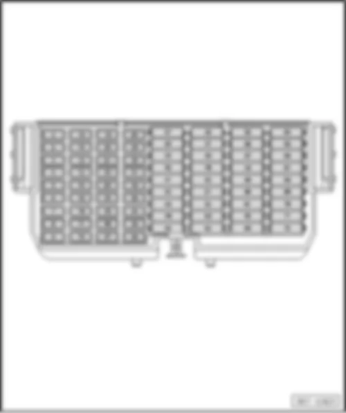
Fuse holder C -SC-(72)
Fitting location
t  driver side dash panel
   
Fuse colours
VW AMAROK 2014 Fuse holder A SA https://portal-diagnostov.com/license.html
https://portal-diagnostov.com/license.html Automotive Electricians Portal FZCO Automotive Electricians Portal FZCO
Получить доступ ко всем электросхемам автомобиляDownload PDF file
40 A -  orange
30 A -  green
25 A -  white
20 A -  yellow
15 A -  blue
10 A -  red
7,5 A -  brown
5 A -  beige
3 A -  purple

Fuse assignment on fuse holder C (from November 2009)
   
No. Current Flow Diagram designation Nominal value Function/component
1 - Fuse 1 on fuse holder C -SC1- 10A -
-
-
ABS control unit -J104-
TCS and ESP button -E256-
Driving program button -E598-
2 - Fuse 2 on fuse holder C -SC2- 10A -
-
-
Left washer jet heater element -Z20-
Right washer jet heater element -Z21-
Steering column combination switch -E595-
t  Windscreen wiper switch -E-
t  Intermittent wiper switch -E22-
t  Washer pump switch (automatic wash/wipe and headlight washer system) -E44-
3 - Fuse 3 on fuse holder C -SC3- 10A -
-
Reversing light switch -F4-4)
Parking aid control unit -J446-4), 8)
15A -
Onboard supply control unit -J519- (T73b/11) 5), 8)
t  Right reversing light bulb -M17- (RFL) 5), 8)
t  Left reversing light bulb -M16- (RFL) 5), 8)
t  Interface for external use (T10h/2) 5), 8)
4 - Fuse 4 on fuse holder C -SC4- 15A -
Onboard supply control unit -J519- (T73b/13)
t  Signal bulb (terminal 49)
t  Brake light bulb (terminal 54)
5 - Fuse 5 on fuse holder C -SC5- 5A -
Air mass meter -G70-
6 - Fuse 6 on fuse holder C -SC6- 5A -
Trailer detector control unit -J345-
7 - Fuse 7 on fuse holder C -SC7- 5A -
Interface for external use (T10h/6)
8 - Fuse 8 on fuse holder C -SC8- 5A -
Ignition/starter switch -D-6)
15A -
Ignition/starter switch -D-7)
9 - Fuse 9 on fuse holder C -SC9- 10A -
-
Airbag control unit -J234-
Front passenger side airbag deactivated warning lamp -K145-
10 - Fuse 10 on fuse holder C -SC10- 5A -
Engine control unit -J623-
11 - Fuse 11 on fuse holder C -SC11- 15A -
Differential lock control unit -J187-
12 - Fuse 12 on fuse holder C -SC12- 10A -
-
Fuel pressure regulating valve -N276-
Fuel metering valve -N290-
10A -
-
-
-
-
Turbocharger air recirculation valve -N249-
Charge pressure control solenoid valve -N75-
Activated charcoal filter solenoid valve 1 -N80-
Camshaft control valve 1 -N205-
Intake manifold flap valve -N316-
13 - Fuse 13 on fuse holder C -SC13- 5A -
-
-
Exhaust flap valve -N220-
Exhaust gas recirculation cooler changeover valve -N345-
Charge pressure control solenoid valve -N75-
14 - Fuse 14 on fuse holder C -SC14- 15A -
-
Continued coolant circulation pump -V51-
Fuel pressure regulating valve -N276-
15 - Fuse 15 on fuse holder C -SC15- 5A -
-
Terminal 30 voltage supply relay -J317-
Circulation pump -V55-
16 - Fuse 16 on fuse holder C -SC16- 10A -
-
-
Rear fog light warning lamp -K13-1)
Rear left fog light bulb -L46-1)
Rear right fog light bulb -L47-1)
5A -
-
Voltage stabiliser -J532-9)
Data bus diagnostic interface -J533-9)
17 - Fuse 17 on fuse holder C -SC17- 5A -
Onboard supply control unit -J519- (T73a/45)
18 - Fuse 18 on fuse holder C -SC18- 7.5A -
Washer pump -V5-
19 - Fuse 19 on fuse holder C -SC19- 15A -
Onboard supply control unit -J519- (T73a/64)
t  Heated exterior mirror on driver side -Z4-
t  Heated exterior mirror on front passenger side -Z5-
20 - Fuse 20 on fuse holder C -SC20- 15A -
Onboard supply control unit -J519- (T73b/39)
t  Internal supply
21 - Fuse 21 on fuse holder C -SC21- 10A -
Onboard supply control unit -J519- (T73a/66)
t  Interior monitoring switch -E183- (30G)
t  Front interior light -W1- (30G)
t  Centre interior light -W7- (30G)
t  Left side light (58L)
t  Right side light (58R)
22 - Fuse 22 on fuse holder C -SC22- 5A -
Control unit for vehicle location system -J895-3)
23 - Fuse 23 on fuse holder C -SC23- 10A -
Engine control unit -J623-
24 - Fuse 24 on fuse holder C -SC24- 10A -
Alarm horn -H12-
25 - Fuse 25 on fuse holder C -SC25- 10A -
Heater element for crankcase breather -N79-
26 - Fuse 26 on fuse holder C -SC26- 5A -
Right daytime running light bulb -L175-1)
27 - Fuse 27 on fuse holder C -SC27- 5A -
Left daytime running light bulb -L174-1)
28 - Fuse 28 on fuse holder C -SC28- 5A -
-
-
-
Light switch -E1-1)
Left number plate light -X4-1)
Right number plate light -X5-1)
B472 Connection 8 in main wiring harness 1)
15A -
Onboard supply control unit -J519- (T73b/11) 5), 9)
t  Left fog light bulb -L22- (NL) 5), 9)
t  Right fog light bulb -L23- (NL) 5), 9)
t  Right reversing light bulb -M17- (RFL) 5), 9)
t  Left reversing light bulb -M16- (RFL) 5), 9)
t  Interface for external use (T10h/2) 5), 9)
29 - Fuse 29 on fuse holder C -SC29- 10A -
-
-
Left headlight range control motor -V48-1)
Left headlight dipped beam bulb -M29-1)
Interface for external use (T10h/4) 1)
5A -
Light switch -E1-2), 9)
30 - Fuse 30 on fuse holder C -SC30- 10A -
-
-
Left headlight main beam bulb -M30-1)
Control unit in dash panel insert -J285-1)
Interface for external use (T10h/8) 1)
5A -
-
Starter relay 1 -J906-9)
Starter relay 2 -J907-9)
31 - Fuse 31 on fuse holder C -SC31- 5A -
-
Tiptronic switch -F189-5)
Automatic gearbox control unit -J217-5)
32 - Fuse 32 on fuse holder C -SC32- 10A -
Right headlight main beam bulb -M32-
33 - Fuse 33 on fuse holder C -SC33- 5A -
Mirror adjustment switch -E43-
34 - Fuse 34 on fuse holder C -SC34- 15A -
Engine control unit -J623-
35 - Fuse 35 on fuse holder C -SC35- 15A -
-
Lambda probe heater -Z19-
Lambda probe 1 heater after catalytic converter -Z29-
36 - Fuse 36 on fuse holder C -SC36- 5A -
-
-
-
-
Fuel pump relay -J17-
Terminal 30 voltage supply relay -J317-
Clutch pedal switch -F36-
Radiator fan control unit -J293-
Automatic glow period control unit -J179-
37 - Fuse 37 on fuse holder C -SC37- 20A -
-
-
-
Ignition coil 1 with output stage -N70-
Ignition coil 2 with output stage -N127-
Ignition coil 3 with output stage -N291-
Ignition coil 4 with output stage -N292-
38 - Fuse 38 on fuse holder C -SC38- 15A -
12 V socket -U5-
39 - Fuse 39 on fuse holder C -SC39- 25A -
Trailer detector control unit -J345-
40 - Fuse 40 on fuse holder C -SC40- 25A -
Trailer detector control unit -J345-
41 - Fuse 41 on fuse holder C -SC41- 25A -
Trailer detector control unit -J345-
42 - Fuse 42 on fuse holder C -SC42- 15A -
-
-
-
-
-
-
-
-
-
-
-
-
-
-
-
Brake light switch -F-
High-pressure sender -G65-
Air quality sensor -G238-
Oil level and oil temperature sender -G266-
Differential lock control unit -J187-
Control unit in dash panel insert -J285-10)
Parking aid control unit -J446-5), 9)
Transfer box control unit -J646-
Control unit for vehicle location system -J895-3)
Normal operation warning lamp in transfer box operating unit -K181-
Reduction gearing warning lamp in transfer box operating unit -K182-
Inter-axle lock-up warning lamp in transfer box operating unit -K183-
High-level brake light bulb -M25-
Fuse 16 on fuse holder C -SC16-9)
Diagnostic connection -U31-
Steering column combination switch -E595-
t  Steering angle sender -G85-
t  Cruise control system switch -E45-
t  Cruise control system (CCS) SET button -E227-
43 - Fuse 43 on fuse holder C -SC43- 25A -
Onboard supply control unit -J519- (T73a/68)
t  Wiper motor control unit -J400-
t  Windscreen wiper motor -V-
44 - Fuse 44 on fuse holder C -SC44- 30A -
Onboard supply control unit -J519- (T73b/67)
t  heated rear window -Z1-
45 - Fuse 45 on fuse holder C -SC45- 15A -
-
-
-
-
-
Diagnostic connection -U31-
Control unit in dash panel insert -J285-
Air conditioning system control unit -J301-
Climatronic control unit -J255-
Heater/heat output switch -E16-
Steering column combination switch -E595-
t  Coil connector -F350-
t  Multifunction steering wheel control unit -J453-
46 - Fuse 46 on fuse holder C -SC46- 25A -
Transfer box control unit -J646-
47 - Fuse 47 on fuse holder C -SC47- 20A -
Onboard supply control unit -J519- (T73a/73)
t  Treble horn -H2-
t  Bass horn -H7-
48 - Fuse 48 on fuse holder C -SC48- 20A -
Driver door control unit -J386-
49 - Fuse 49 on fuse holder C -SC49- 20A -
Front passenger door control unit -J387-
50 - Fuse 50 on fuse holder C -SC50- 20A -
Rear left door control unit -J388-
51 - Fuse 51 on fuse holder C -SC51- 20A -
Rear right door control unit -J389-
52 - Fuse 52 on fuse holder C -SC52- 15A -
Electric socket -U-
53 - Fuse 53 on fuse holder C -SC53- 20A -
-
Left fog light bulb -L22-1)
Right fog light bulb -L23-1)
25A -
Onboard supply control unit -J519- (T73a/63) 2)
54 - Fuse 54 on fuse holder C -SC54- 15A -
Cigarette lighter -U1-
55 - Fuse 55 on fuse holder C -SC55- 15A -
-
-
-
Right headlight range control motor -V49-1)
Headlight range control regulator -E102-1)
Right headlight dipped beam bulb -M31-1)
Interface for external use (T10h/5) 1)
25A -
Onboard supply control unit -J519- (T73b/68) 2)
t  Right daytime running light bulb -L175-2)
t  Right headlight dipped beam bulb -M31-2)
t  Interface for external use (T10h/5) 2)
56 - Fuse 56 on fuse holder C -SC56- 25A -
Fuel pump control unit -J538-
57 - Fuse 57 on fuse holder C -SC57- 30A -
-
-
Button for left seat heating -E653-
Button for right seat heating -E654-
Seat heating control unit -J882-
58 - Fuse 58 on fuse holder C -SC58- 15A -
-
-
Tiptronic switch -F189-5)
Automatic gearbox control unit -J217-5)
Ignition key withdrawal lock solenoid -N376-5)
59 - Fuse 59 on fuse holder C -SC59- 20A -
12 V socket 2 -U18-
60 - Fuse 60 on fuse holder C -SC60- 5A -
Trailer detector control unit -J345-11)
61 - Fuse 61 on fuse holder C -SC61- 5A -
Trailer detector control unit -J345-11)
62 - Fuse 62 on fuse holder C -SC62- 20A -
-
-
Auxiliary heater control unit -J364-
Coolant pump relay -J235-
Auxiliary coolant heater relay -J493-
t  Circulation pump -V55-
63 - Fuse 63 on fuse holder C -SC63- 10A -
Load area illumination bulb -M53-
64 - Fuse 64 on fuse holder C -SC64- 40A -
-
-
Heater/heat output switch -E16-
Climatronic control unit -J255-
Air conditioning system control unit -J301-
65 - Fuse 65 on fuse holder C -SC65- 15A -
Engine control unit -J623-
66 - Fuse 66 on fuse holder C -SC66- 30A -
Onboard supply control unit -J519- (T73a/16)
t  Fuel tank filler flap central locking actuator -F219-
t  Driver side central locking lock unit -F220-
t  Front passenger side central locking lock unit -F221-
t  Rear left central locking lock unit -F222-
t  Rear right central locking lock unit -F223-
67 - Fuse 67 on fuse holder C -SC67- 30A -
-
Radio -R-8)
Control unit with display for radio and navigation -J503-8)
30A -
-
Voltage stabiliser -J532-9)
Data bus diagnostic interface -J533-9)
68 - Fuse 68 on fuse holder C -SC68- 7.5A -
Telephone controls control unit -J738-
69 - Fuse 69 on fuse holder C -SC69- 15A -
Interface for external use (T10h/1)
70 - Fuse 70 on fuse holder C -SC70- 5A -
Interface for external use (T10h/9)
71 - Fuse 71 on fuse holder C -SC71- 25A -
Interface for external use (T6h/3)
72 - Fuse 72 on fuse holder C -SC72- 10A -
Interface for external use (T6h/5)

  Note:
t  1) Only models with connector, 17-pin -T17- on light switch -E1- (external lighting 7L3/8K0/8K1)
t  2) Only models with connector, 10-pin -T10j- on light switch -E1- (external lighting 7L3/8K3/8K8 or 7L6/8K0/8K1/8K3/8K8)
t  3) Only models with Control unit for vehicle location system -J895-
t  4) Only models with manual gearbox
t  5) Only models with automatic gearbox
t  6) Valid until April 2011
t  7) Valid from May 2011
t  8) Only models with no start/stop system (7L3)
t  9) Only models with start/stop system (7L6)
t  10) Only models with no Control unit for vehicle location system -J895-
t  11) only vehicles with trailer towing coupling
–  Back to overview → Chapter
Fuse assignment, from June 2012
   
No. Current Flow Diagram designation Nominal value -
Function/component
1 - Fuse 1 on fuse holder C -SC1- 10A -
-
-
-
-
-
ABS control unit -J104-
TCS and ESP button -E256-
Driving program button -E598-
Airbag control unit -J234-
Front passenger side airbag deactivated warning lamp -K145-
Light switch -E1-10)
2 - Fuse 2 on fuse holder C -SC2- 10A -
Steering column combination switch -E595-
t  Windscreen wiper switch -E-
t  Intermittent wiper switch -E22-
t  Washer pump switch (automatic wash/wipe and headlight washer system) -E44-
3 - Fuse 3 on fuse holder C -SC3- 15A -
-
-
-
-
-
-
Light switch -E1-1), 9)
Automatic gearbox control unit -J217-2)
Heater/heat output switch -E16-2), 5)
Air conditioning system control unit -J301-2), 5)
Potentiometer for front air distribution flap control motor -G642-2), 4)
Climatronic control unit -J255-2), 4)
Auxiliary coolant heater relay -J493-2), 4)
t  Circulation pump -V55-2), 4)
4 - Fuse 4 on fuse holder C -SC4- 15A -
-
Engine control unit -J623-8)
Air mass meter -G70-2), 8)
5 - Fuse 5 on fuse holder C -SC5- 5A -
Air mass meter -G70-1), 8)
15A -
-
-
-
Ignition coil 1 with output stage -N70-2), 7)
Ignition coil 2 with output stage -N127-2), 7)
Ignition coil 3 with output stage -N291-2), 7)
Ignition coil 4 with output stage -N292-2), 7)
6 - Fuse 6 on fuse holder C -SC6- 5A -
Trailer detector control unit -J345-
7 - Fuse 7 on fuse holder C -SC7- 5A -
Interface for external use (T10h/6)
8 - Fuse 8 on fuse holder C -SC8- 15A -
-
-
Ignition/starter switch -D-
Alarm horn -H12-
Control unit for vehicle location system -J895-2), 13)
9 - Fuse 9 on fuse holder C -SC9- 5A -
Load area illumination bulb -M53-
10 - Fuse 10 on fuse holder C -SC10- 5A -
-
-
-
Tiptronic switch -F189-
Automatic gearbox control unit -J217-
Air mass meter -G70-7)
Engine control unit -J623-8)
11 - Fuse 11 on fuse holder C -SC11- 15A -
Differential lock control unit -J187-
12 - Fuse 12 on fuse holder C -SC12- 10A -
-
-
-
-
-
-
Charge pressure control solenoid valve -N75-7)
Activated charcoal filter solenoid valve 1 -N80-7)
Camshaft control valve 1 -N205-7)
Turbocharger air recirculation valve -N249-7)
Intake manifold flap valve -N316-7)
Fuel pressure regulating valve -N276-8)
Fuel metering valve -N290-8)
13 - Fuse 13 on fuse holder C -SC13- 7.5A -
-
-
-
Button for left seat heating -E653-
Button for right seat heating -E654-
Left washer jet heater element -Z20-
Right washer jet heater element -Z21-
14 - Fuse 14 on fuse holder C -SC14- 15A -
Fuel pressure regulating valve -N276-7)
15 - Fuse 15 on fuse holder C -SC15- 5A -
Terminal 30 voltage supply relay -J317-
t  Circulation pump -V55-
16 - Fuse 16 on fuse holder C -SC16- 10A -
-
-
Rear fog light warning lamp -K13-9)
Rear left fog light bulb -L46-9)
Rear right fog light bulb -L47-9)
5A -
Voltage stabiliser -J532-12)
17 - Fuse 17 on fuse holder C -SC17- 5A -
Onboard supply control unit -J519- (T73a/45)
18 - Fuse 18 on fuse holder C -SC18- 7.5A -
Washer pump -V5-1)
10A -
Washer pump -V5-2)
19 - Fuse 19 on fuse holder C -SC19- 15A 1)
10A 2)
-
Onboard supply control unit -J519- (T73a/64)
t  Heated exterior mirror on driver side -Z4-
t  Heated exterior mirror on front passenger side -Z5-
20 - Fuse 20 on fuse holder C -SC20- 15A 1)
5A 2)
-
Onboard supply control unit -J519- (T73b/39)
t  Internal supply
 
21 - Fuse 21 on fuse holder C -SC21- 15A -
Onboard supply control unit -J519- (T73a/66)
t  Interior monitoring switch -E183- (30G)
t  Front interior light -W1- (30G)
t  Centre interior light -W7- (30G)
t  Left side light (58L)
t  Right side light (58R)
22 - Fuse 22 on fuse holder C -SC22- - -
Not assigned1)
10A -
Reversing camera system control unit -J772-2)
23 - Fuse 23 on fuse holder C -SC23- 10A -
Engine control unit -J623-
24 - Fuse 24 on fuse holder C -SC24- 5A -
Steering column combination switch -E595-
t  Headlight dipper and flasher switch -E4-
25 - Fuse 25 on fuse holder C -SC25- 10A -
Heater element for crankcase breather -N79-
26 - Fuse 26 on fuse holder C -SC26- 5A -
Right daytime running light bulb -L175-9)
27 - Fuse 27 on fuse holder C -SC27- 5A -
Left daytime running light bulb -L174-9)
28 - Fuse 28 on fuse holder C -SC28- 5A -
B472 Connection 8 in main wiring harness 9)
t  Light switch -E1-9)
t  Headlight range control regulator -E102-9)
t  Left number plate light -X4-9)
t  Right number plate light -X5-9)
15A -
Onboard supply control unit -J519- (T73b/11) 10)
t  Left fog light bulb -L22- (NL) 10)
t  Right fog light bulb -L23- (NL) 10)
t  Right reversing light bulb -M17- (RFL) 10)
t  Left reversing light bulb -M16- (RFL) 10)
t  Interface for external use (T10h/2) 10)
29 - Fuse 29 on fuse holder C -SC29- 10A -
-
Left headlight dipped beam bulb -M29-9)
Interface for external use (T10h/4) 9)
5A -
Light switch -E1-10)
30 - Fuse 30 on fuse holder C -SC30- 10A -
-
-
-
-
Left headlight main beam bulb -M30-
Control unit in dash panel insert -J285-
Interface for external use (T10h/8)
Interface for external use (T10b/1) 2), 10)
Onboard supply control unit -J519- (T73a/62) 10)
31 - Fuse 31 on fuse holder C -SC31- 5A -
Interface for external use (T10h/9)
32 - Fuse 32 on fuse holder C -SC32- 10A -
Right headlight main beam bulb -M32-
33 - Fuse 33 on fuse holder C -SC33- 5A -
Mirror adjustment switch -E43-
34 - Fuse 34 on fuse holder C -SC34- 15A -
-
Engine control unit -J623-7)
Continued coolant circulation pump -V51-8)
35 - Fuse 35 on fuse holder C -SC35- 15A -
-
Lambda probe heater -Z19-
Lambda probe 1 heater after catalytic converter -Z29-
36 - Fuse 36 on fuse holder C -SC36- 5A -
-
-
Fuel pump relay -J17-
Terminal 30 voltage supply relay -J317-
Clutch pedal switch -F36-
37 - Fuse 37 on fuse holder C -SC37- 20A -
-
-
-
Ignition coil 1 with output stage -N70-1), 7)
Ignition coil 2 with output stage -N127-1), 7)
Ignition coil 3 with output stage -N291-1), 7)
Ignition coil 4 with output stage -N292-1), 7)
- -
Not assigned2)
38 - Fuse 38 on fuse holder C -SC38- 40A -
-
-
-
-
-
-
-
Fuse 28 on fuse holder C -SC28-2), 10)
Fuse 29 on fuse holder C -SC29-10)
Fuse 55 on fuse holder C -SC55-10)
Fuel pump relay -J17-7)
Headlight relay -J25-10)
Starter motor relay -J53-11)
Main relay -J271-
Terminal 58b relief relay -J374-9)
39 - Fuse 39 on fuse holder C -SC39- 25A 1)
20A 2)
-
Trailer detector control unit -J345-
40 - Fuse 40 on fuse holder C -SC40- 25A 1)
20A 2)
-
Trailer detector control unit -J345-
41 - Fuse 41 on fuse holder C -SC41- 25A 1)
20A 2)
-
Trailer detector control unit -J345-
42 - Fuse 42 on fuse holder C -SC42- 15A 1)
10A 2)
-
-
-
-
-
-
-
-
-
-
-
-
-
-
-
-
Start/Stop operation button -E693-12)
Brake light switch -F-
Reversing light switch -F4-
Tachograph -G24-
High-pressure sender -G65-
Air quality sensor -G238-
Oil level and oil temperature sender -G266-
Differential lock control unit -J187-
Parking aid control unit -J446-
Transfer box control unit -J646-
Normal operation warning lamp in transfer box operating unit -K181-
Reduction gearing warning lamp in transfer box operating unit -K182-
Inter-axle lock-up warning lamp in transfer box operating unit -K183-
High-level brake light bulb -M25-
Diagnostic connection -U31-
Steering column combination switch -E595-
t  Steering angle sender -G85-
t  Cruise control system switch -E45-
t  Cruise control system (CCS) SET button -E227-
t  Coil connector -F350-
t  Multifunction steering wheel control unit -J453-
43 - Fuse 43 on fuse holder C -SC43- 30A -
Onboard supply control unit -J519- (T73a/68) 1)
t  Wiper motor control unit -J400-1)
t  Windscreen wiper motor -V-1)
25A -
Light switch -E1-2), 9)
30A -
Voltage stabiliser -J532-2), 12)
t  Control unit in dash panel insert -J285-2), 12)
t  Fuse 67 on fuse holder C -SC67-2), 12)
44 - Fuse 44 on fuse holder C -SC44- 30A -
Onboard supply control unit -J519- (T73b/67)
t  Heated rear window relay -J9-
t  heated rear window -Z1-
45 - Fuse 45 on fuse holder C -SC45- 15A 1)
10A 2)
-
-
-
-
-
-
-
-
-
-
-
-
-
-
-
Heater/heat output switch -E16-1)
Diagnostic connection -U31-
Control unit in dash panel insert -J285-11)
Climatronic control unit -J255-4)
Sender for front Bitron blower regulation -G462-4)
Rain and light sensor -G397-
Interior monitoring sensor -G273-
Telephone controls control unit -J738-
Tachograph -G24-
Tiptronic switch -F189-2)
Ignition key withdrawal lock solenoid -N376-2)
Electric fuel pump 2 relay -J49-2)
Roof display unit -J702-2)
Remote control receiver for auxiliary coolant heater -R149-2)
Steering column combination switch -E595-
t  Coil connector -F350-
t  Multifunction steering wheel control unit -J453-
46 - Fuse 46 on fuse holder C -SC46- 25A 1)
30A 2)
-
Transfer box control unit -J646-
47 - Fuse 47 on fuse holder C -SC47- 25A -
Onboard supply control unit -J519- (T73a/73)
t  Treble horn -H2-
t  Bass horn -H7-
48 - Fuse 48 on fuse holder C -SC48- 30A -
Driver door control unit -J386-
49 - Fuse 49 on fuse holder C -SC49- 30A -
Front passenger door control unit -J387-
50 - Fuse 50 on fuse holder C -SC50- 30A -
Rear left door control unit -J388-
51 - Fuse 51 on fuse holder C -SC51- 30A -
Rear right door control unit -J389-
52 - Fuse 52 on fuse holder C -SC52- 30A -
-
Electric socket -U-
Cigarette lighter -U1-
53 - Fuse 53 on fuse holder C -SC53- 25A 1)
20A 2)
-
Onboard supply control unit -J519- (T73a/63) 10)
t  Left daytime running light bulb -L174-10)
t  Left headlight dipped beam bulb -M29-10)
54 - Fuse 54 on fuse holder C -SC54- 20A -
Light switch -E1-9)
55 - Fuse 55 on fuse holder C -SC55- 15A 1)
10A 2)
-
-
-
Headlight range control regulator -E102-1), 9)
Right headlight dipped beam bulb -M31-9)
Interface for external use (T10h/5) 9)
25A 1)
20A 2)
-
Onboard supply control unit -J519- (T73b/68) 10)
t  Right daytime running light bulb -L175-10)
t  Right headlight dipped beam bulb -M31-10)
t  Interface for external use (T10h/5) 1), 10)
56 - Fuse 56 on fuse holder C -SC56- 25A -
Fuel pump control unit -J538-7)
57 - Fuse 57 on fuse holder C -SC57- 30A 1)
25A 2)
-
Seat heating control unit -J882-
58 - Fuse 58 on fuse holder C -SC58- 15A 1)
-
-
-
Tiptronic switch -F189-1)
Automatic gearbox control unit -J217-1)
Ignition key withdrawal lock solenoid -N376-1)
30A 2)
-
Onboard supply control unit -J519- (T73a/68) 2)
t  Wiper motor control unit -J400-2)
t  Windscreen wiper motor -V-2)
59 - Fuse 59 on fuse holder C -SC59- 25A -
-
12 V socket 2 -U18-
12 V socket 3 -U19-
60 - Fuse 60 on fuse holder C -SC60- 20A -
-
-
Left fog light bulb -L22-9)
Right fog light bulb -L23-9)
Interface for external use (T10h/2) 9)
5A -
Interface for external use (T10h/2) 10)
61 - Fuse 61 on fuse holder C -SC61- 30A 1)
15A 2)
-
Onboard supply control unit -J519- (T73b/11) 9)
t  Left fog light bulb -L22- (NL) 9), 14)
t  Right fog light bulb -L23- (NL) 9), 14)
t  Right reversing light bulb -M17- (RFL) 9), 15)
t  Left reversing light bulb -M16- (RFL) 9), 15)
t  Interface for external use (T10h/2) 9), 15)
62 - Fuse 62 on fuse holder C -SC62- 20A1) -
-
-
-
-
-
Auxiliary heater control unit -J364-
Fresh air blower relay -J13-
Electric fuel pump 2 relay -J49-
Roof display unit -J702-
Remote control receiver for auxiliary coolant heater -R149-
Coolant pump relay -J235-6)
15A2) -
-
-
Auxiliary heater control unit -J364-
Fresh air blower relay -J13-
Coolant pump relay -J235-6)
30A3) -
-
-
-
-
Auxiliary heater control unit -J364-
Fresh air blower relay -J13-
Electric fuel pump 2 relay -J49-1)
Roof display unit -J702-1)
Remote control receiver for auxiliary coolant heater -R149-1)
63 - Fuse 63 on fuse holder C -SC63- 30A -
Light switch -E1-9)
5A -
-
-
Light switch -E1-12)
Starter relay 1 -J906-12)
Starter relay 2 -J907-12)
64 - Fuse 64 on fuse holder C -SC64- 40A -
Fresh air blower -V2-4)
65 - Fuse 65 on fuse holder C -SC65- 15A -
Onboard supply control unit -J519- (T73b/13)
t  Signal bulb (terminal 49)
t  Brake light bulb (terminal 54)
66 - Fuse 66 on fuse holder C -SC66- 30A -
Onboard supply control unit -J519- (T73a/16)
t  Fuel tank filler flap central locking actuator -F219-
t  Driver side central locking lock unit -F220-
t  Front passenger side central locking lock unit -F221-
t  Rear left central locking lock unit -F222-
t  Rear right central locking lock unit -F223-
67 - Fuse 67 on fuse holder C -SC67- 30A -
-
-
Control unit with display for radio and navigation -J503-1), 9)
Radio -R-1), 9)
Voltage stabiliser -J532-1), 10)
t  Control unit in dash panel insert -J285-1), 10)
t  Control unit with display for radio and navigation -J503-1), 10)
t  Radio -R-1), 10)
25A -
-
Radio -R-2)
Control unit with display for radio and navigation -J503-2)
68 - Fuse 68 on fuse holder C -SC68- 40A -
-
-
Heater/heat output switch -E16-5)
Air conditioning system control unit -J301-1), 5)
Fresh air blower isolation relay -J487-2), 5)
t  Air conditioning system control unit -J301-2), 5)
69 - Fuse 69 on fuse holder C -SC69- 15A -
Interface for external use (T10h/1)
70 - Fuse 70 on fuse holder C -SC70- - -
Not assigned11)
40A 1)
30A 2)
-
-
Starter relay 1 -J906-12)
Starter relay 2 -J907-12)
71 - Fuse 71 on fuse holder C -SC71- 30A -
Interface for external use (T6h/3)
72 - Fuse 72 on fuse holder C -SC72- 10A 1)
5A 2)
-
Interface for external use (T6h/5)

  Note:
t  1) Valid until December 2012
t  2) Valid from January 2013
t  3) Only models with Climatic
t  4) Only models with Climatronic
t  5) Only models with no Climatronic
t  6) Only models with Climatronic and petrol engine
t  7) Only models with petrol engine
t  8) Only models with diesel engine
t  9) Only models with connector, 17-pin -T17- on light switch -E1- (external lighting 7L3/8K0/8K1)
t  10) Only models with connector, 10-pin -T10j- on light switch -E1- (external lighting 7L3/8K3/8K8 or 7L6/8K0/8K1/8K3/8K8)
t  11) Only models with no start/stop system (7L3)
t  12) Only models with start/stop system (7L6)
t  13) Only models with no Control unit for vehicle location system -J895-
t  14) only vehicles with cornering lights
t  15) Only models with automatic gearbox
–  Back to overview → Chapter
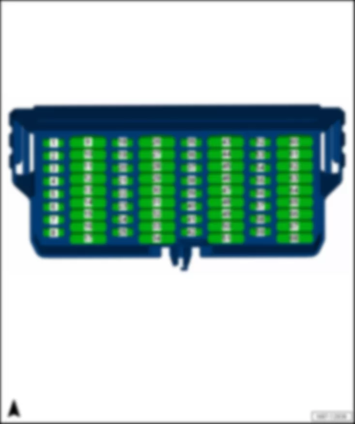
Fuse holder C -SC-(68-pin)
Fitting location
t  driver side dash panel
   
Fuse colours
VW AMAROK 2014 Fuse holder A SA https://portal-diagnostov.com/license.html
https://portal-diagnostov.com/license.html Automotive Electricians Portal FZCO Automotive Electricians Portal FZCO
Получить доступ ко всем электросхемам автомобиляDownload PDF file
40 A -  orange
30 A -  green
25 A -  white
20 A -  yellow
15 A -  blue
10 A -  red
7,5 A -  brown
5 A -  beige
3 A -  purple

Fuse assignment, from July 2013
   
No. Current Flow Diagram designation Nominal value Function/component
1 - Fuse 1 on fuse holder C -SC1- 10A -
Washer pump -V5-
2 - Fuse 2 on fuse holder C -SC2- 15A -
-
-
-
-
-
-
Heater/heat output switch -E16-10)
Sender for front Bitron blower regulation -G462-10)
Climatronic control unit -J255-10)
Air conditioning system control unit -J301-10)
Control unit for vehicle location system -J895-8), 11)
Automatic gearbox control unit -J217-
Onboard supply control unit -J519- (T73b/39) 11)
t  Internal supply
3 - Fuse 3 on fuse holder C -SC3- 15A -
-
-
Ignition/starter switch -D-
Control unit for vehicle location system -J895-8), 10)
Onboard supply control unit -J519- (T73b/39) 10)
t  Internal supply
4 - Fuse 4 on fuse holder C -SC4- 15A -
-
-
Alarm horn -H12-
Terminal 30 voltage supply relay -J317-
Steering column combination switch -E595-
t  Headlight dipper and flasher switch -E4-
5 - Fuse 5 on fuse holder C -SC5- 15A -
Differential lock control unit -J187-
6 - Fuse 6 on fuse holder C -SC6- 15A -
Onboard supply control unit -J519- (T73b/11)
t  Left fog light bulb -L22- (NL) 6) or 5) with 16)
t  Right fog light bulb -L23- (NL) 6) or 5) with 16)
t  Left reversing light bulb -M16- (RFL) 6) or 5) with 9)
t  Right reversing light bulb -M17- (RFL) 6) or 5) with 9)
t  Interface for external use (T10h/2) 6), 17) or 5), 17) with 9), 17)
t  Interface for external use (T17j/2) 6), 18) or 5), 18) with 9), 18)
7 - Fuse 7 on fuse holder C -SC7- 15A -
Onboard supply control unit -J519- (T73a/66)
t  Interior monitoring switch -E183- (30G)
t  Front interior light -W1- (30G)
t  Centre interior light -W7- (30G)
t  Left side light (58L)
t  Right side light (58R)
8 - Fuse 8 on fuse holder C -SC8- 15A -
Trailer detector control unit -J345-
9 - Fuse 9 on fuse holder C -SC9- 40A 10)
30A 11)
-
-
-
-
Headlight relay -J25-6)
Starter motor relay -J53-3)
Current supply relay for Motronic -J271-
Terminal 58b relief relay -J374-5)
10 - Fuse 10 on fuse holder C -SC10- 20A -
Trailer detector control unit -J345-
11 - Fuse 11 on fuse holder C -SC11- 20A -
Trailer detector control unit -J345-
12 - Fuse 12 on fuse holder C -SC12- 30A -
Transfer box control unit -J646-
13 - Fuse 13 on fuse holder C -SC13- 30A -
Driver door control unit -J386-
14 - Fuse 14 on fuse holder C -SC14- 30A -
Front passenger door control unit -J387-
15 - Fuse 15 on fuse holder C -SC15- 20A1) -
-
-
-
Coolant pump relay -J235-17)
Terminal 30 voltage supply relay -J317-17)
Auxiliary coolant heater relay -J493-17)
Auxiliary heater control unit -J364-17)
30A2) -
-
-
-
Fresh air blower relay -J13-17)
Terminal 30 voltage supply relay -J317-17)
Auxiliary coolant heater relay -J493-17)
Auxiliary heater control unit -J364-17)
20A -
Auxiliary heater control unit -J364-18)
16 - Fuse 16 on fuse holder C -SC16- 20A -
Onboard supply control unit -J519- (T73b/13)
t  Signal bulb (terminal 49)
t  Brake light bulb (terminal 54)
17 - Fuse 17 on fuse holder C -SC17- 25A -
-
-
Control unit with display for radio and navigation -J503-3)
Radio -R-3)
8-pin connector -T8c-3)
18 - Fuse 18 on fuse holder C -SC18- 5A -
Dash panel insert -K-4)
19 - Fuse 19 on fuse holder C -SC19- 10A 17)
5A 18)
-
-
-
Rear left fog light bulb -L46-5)
Rear right fog light bulb -L47-5)
Rear fog light warning lamp -K13-5)
20 - Fuse 20 on fuse holder C -SC20- 5A -
Onboard supply control unit -J519- (T73a/45) 5)
21 - Fuse 21 on fuse holder C -SC21- 5A -
-
Left daytime running light bulb -L174-5)
Right daytime running light bulb -L175-5)
22 - Fuse 22 on fuse holder C -SC22- 10A -
-
-
-
-
A7 Positive connection (58 D1) in dash panel wiring harness 5)
B342 Connection 3 (58d) in main wiring harness 5)
B472 Connection 8 in main wiring harness 5)
N2 Connection 1 in wiring harness headlight range control 5), 10)
R14 Connection 1 (on) in wiring harness door wiring driver side 5)
23 - Fuse 23 on fuse holder C -SC23- 5A -
-
-
-
-
-
-
-
-
-
Clutch pedal switch -F36-
Air mass meter -G70-11)
Fuel pump relay -J17-
Automatic glow period control unit -J179-
Coolant pump relay -J235-
Radiator fan control unit -J293-
Terminal 30 voltage supply relay -J317-
Charge pressure control solenoid valve -N75-
Exhaust flap valve -N220-
Exhaust gas recirculation cooler changeover valve -N345-
24 - Fuse 24 on fuse holder C -SC24- 10A -
-
Fuel pressure regulating valve -N276-
Fuel metering valve -N290-
-
-
-
-
-
Charge pressure control solenoid valve -N75-
Activated charcoal filter solenoid valve 1 -N80-
Camshaft control valve 1 -N205-
Turbocharger air recirculation valve -N249-
Intake manifold flap valve -N316-
25 - Fuse 25 on fuse holder C -SC25- 5A -
Continued coolant circulation pump -V51-
15A -
Engine control unit -J623-
26 - Fuse 26 on fuse holder C -SC26- 10A 17)
7.5A 18)
-
-
Interface for external use (T10h/4) 5), 10)
Front left headlight -MX1-5)
t  Left headlight dipped beam bulb -M29-5)
27 - Fuse 27 on fuse holder C -SC27- 10A 13)
15A 14)
-
-
-
-
-
-
-
-
Onboard supply control unit -J519- (T73a/62)
Front left headlight -MX1-12
Front right headlight -MX2-12), 14)
Interface for external use (T10b/1) 17)
Interface for external use (T10h/8) 17)
Interface for external use (T17j/8) 18)
Interface for external use (T17k/1) 18)
Control unit in dash panel insert -J285-
t  Main beam warning lamp -K1-
28 - Fuse 28 on fuse holder C -SC28- 10A -
-
-
-
-
Interface for external use (T10h/4) 5), 11), 17)
Interface for external use (T10h/5) 5), 17)
Interface for external use (T17j/4) 5), 18)
Interface for external use (T17j/5) 5), 18)
Front right headlight -MX2-5)
t  Right headlight dipped beam bulb -M31-5)
29 - Fuse 29 on fuse holder C -SC29- 10A -
Front right headlight -MX2-12), 13)
t  Right headlight main beam bulb -M32-12), 13)
- -
Not assigned14), 17)
10A -
-
-
-
-
-
Tiptronic switch -F189-18)
Tachograph -G24-18)
Ignition key withdrawal lock solenoid -N376-18)
Remote control receiver for auxiliary coolant heater -R149-18)
Diagnostic connection -U31-18)
Steering column combination switch -E595-18)
t  Coil connector -F350-18)
t  Multifunction steering wheel control unit -J453-18)
30 - Fuse 30 on fuse holder C -SC30- 5A -
-
Interface for external use (T10h/2) 6), 17)
Interface for external use (T17j/2) 6), 18)
20A -
-
-
-
Left fog light bulb -L22-5)
Right fog light bulb -L23-5)
Interface for external use (T10h/2) 5), 17)
Interface for external use (T17j/17) 5), 18)
31 - Fuse 31 on fuse holder C -SC31- 30A 13)
15A 14)
-
-
Interface for external use (T6h/3) 17)
Interface for external use (T17j/15) 18)
t  Ignition/starter switch -D-
t  Terminal 15 voltage supply relay -J329-
t  Onboard supply control unit -J519- (T73a/44)
t  Steering column combination switch -E595-
t  Washer pump switch (automatic wash/wipe and headlight washer system) -E44-
32 - Fuse 32 on fuse holder C -SC32- 15A -
-
Lambda probe heater -Z19-
Lambda probe 1 heater after catalytic converter -Z29-
33 - Fuse 33 on fuse holder C -SC33- 15A -
-
-
-
Ignition coil 1 with output stage -N70-
Ignition coil 2 with output stage -N127-
Ignition coil 3 with output stage -N291-
Ignition coil 4 with output stage -N292-
20A -
-
Air mass meter -G70-10)
Engine control unit -J623-
34 - Fuse 34 on fuse holder C -SC34- 20A -
Fuel pump control unit -J538-
t  Fuel system pressurisation pump -G6-
35 - Fuse 35 on fuse holder C -SC35- 5A -
-
Button for left seat heating -E653-
Button for right seat heating -E654-
36 - Fuse 36 on fuse holder C -SC36- 5A -
Mirror adjustment switch -E43-
37 - Fuse 37 on fuse holder C -SC37- 15A -
-
Interface for external use (T10h/1) 17)
Interface for external use (T17j/1) 18)
38 - Fuse 38 on fuse holder C -SC38- 5A -
-
-
-
Tiptronic switch -F189-
Automatic gearbox control unit -J217-Air mass meter -G70-
Engine control unit -J623-
Voltage stabiliser -J532-4)
39 - Fuse 39 on fuse holder C -SC39- 10A -
-
Airbag control unit -J234-
Front passenger side airbag deactivated warning lamp -K145-
40 - Fuse 40 on fuse holder C -SC40- 5A -
-
-
-
-
-
-
Heater/heat output switch -E16-14)
TCS and ESP button -E256-
Driving program button -E598-
ABS control unit -J104-
Alarm system relay 1 -J460-14), 15)
Dash panel insert -K-7)
Steering column combination switch -E595-
t  Steering angle sender -G85-
41 - Fuse 41 on fuse holder C -SC41- 10A -
-
-
-
-
-
-
-
-
Headlight range control regulator -E102-
Trailer detector control unit -J345-
Heater element for crankcase breather -N79-
8-pin connector -T8f-
Automatic anti-dazzle interior mirror -Y7-
Left headlight range control motor -V48-
Right headlight range control motor -V49-
Left washer jet heater element -Z20-
Right washer jet heater element -Z21-
42 - Fuse 42 on fuse holder C -SC42- 10A -
-
-
-
-
-
-
-
-
-
-
-
-
-


-
Start/Stop operation button -E693-4)
Brake light switch -F-
Reversing light switch -F4-
Tachograph -G24-
High-pressure sender -G65-
Air quality sensor -G238-
Oil level and oil temperature sender -G266-
Differential lock control unit -J187-
Parking aid control unit -J446-
Transfer box control unit -J646-
Normal operation warning lamp in transfer box operating unit -K181-
Load area illumination bulb -M53-
Diagnostic connection -U31-
Control unit for vehicle location system -J895-8)
t  Dash panel insert -K-8)

Steering column combination switch -E595-
t  Cruise control system switch -E45-
t  Cruise control system (CCS) SET button -E227-
t  Coil connector -F350-
t  Multifunction steering wheel control unit -J453-
43 - Fuse 43 on fuse holder C -SC43- 25A -
-
Electric socket -U-
Cigarette lighter -U1-
44 - Fuse 44 on fuse holder C -SC44- 20A -
Light switch -E1-5)
45 - Fuse 45 on fuse holder C -SC45- 25A -
Seat heating control unit -J882-
46 - Fuse 46 on fuse holder C -SC46- 25A -
-
12 V socket 2 -U18-
12 V socket 3 -U19-
47 - Fuse 47 on fuse holder C -SC47- 5A -
-

Interface for external use (T6h/5) 17)
Interface for external use (T17k/11) 18)
t  Ignition/starter switch -D-3)
t  Current supply relay -J16-
t  Onboard supply control unit -J519- (T73b/51) 3)
t  Voltage supply relay 2 -J710-3)
t  Heater/heat output switch -E16-11), 13)
48 - Fuse 48 on fuse holder C -SC48- 25A -
-
-
Control unit with display for radio and navigation -J503-4)
Radio -R-4)
8-pin connector -T8c-4)
49 - Fuse 49 on fuse holder C -SC49- 5A -
-
-
Light switch -E1-6)
Starter relay 1 -J906-4)
Starter relay 2 -J907-4)
20A -
Light switch -E1-5)
50 - Fuse 50 on fuse holder C -SC50- 5A -
-
Interface for external use (T10h/9) 17)
Interface for external use (T17j/9) 18)
51 - Fuse 51 on fuse holder C -SC51- 30A -
Starter relay 1 -J906-4)
t  Starter relay 2 -J907-4)
t  Starter -B-4)
52 - Fuse 52 on fuse holder C -SC52- 5A -
-
Interface for external use (T10h/6) 17)
Interface for external use (T17j/6) 18)
53 - Fuse 53 on fuse holder C -SC53- 5A -
-
Control unit for special installations -J980-10)
Load area illumination bulb -M53-10)
15A 17)
10A 18)
-
-
-
-
-
Heater/heat output switch -E16-11)
Tachograph -G24-11), 17)
Sender for front Bitron blower regulation -G462-11)
Climatronic control unit -J255-11)
Air conditioning system control unit -J301-11)
54 - Fuse 54 on fuse holder C -SC54- 5A -
Dash panel insert -K-3)
55 - Fuse 55 on fuse holder C -SC55- 15A -
Onboard supply control unit -J519- (T73a/64)
t  Suppression filter -C10-
t  Heated exterior mirror on driver side -Z4-
t  Heated exterior mirror on front passenger side -Z5-
56 - Fuse 56 on fuse holder C -SC56- 10A -
Reversing camera system control unit -J772-
57 - Fuse 57 on fuse holder C -SC57- 5A -
Engine control unit -J623-
58 - Fuse 58 on fuse holder C -SC58- 5A -
Light switch -E1-6)
59 - Fuse 59 on fuse holder C -SC59- 10A -
-
-
-
-
-
-
-
-
-
-
-
-
-
-
-
Tiptronic switch -F189-17)
Tachograph -G24-10)
Interior monitoring sensor -G273-
Rain and light sensor -G397-
Electric fuel pump 2 relay -J49-
Roof display unit -J702-
Telephone controls control unit -J738-
Ignition key withdrawal lock solenoid -N376-17)
Remote control receiver for auxiliary coolant heater -R149-17)
Diagnostic connection -U31-17)
Control unit for special installations -J980-11)
Load area illumination bulb -M53-11)
Coolant pump relay -J235-18)
Terminal 30 voltage supply relay -J317-18)
Auxiliary coolant heater relay -J493-18)
Steering column combination switch -E595-17)
t  Coil connector -F350-17)
t  Multifunction steering wheel control unit -J453-17)
60 - Fuse 60 on fuse holder C -SC60- 25A -
Onboard supply control unit -J519- (T73a/16)
t  Fuel tank filler flap central locking actuator -F219-
t  Driver side central locking lock unit -F220-
t  Front passenger side central locking lock unit -F221-
t  Rear left central locking lock unit -F222-
t  Rear right central locking lock unit -F223-
61 - Fuse 61 on fuse holder C -SC61- 15A -
Light switch -E1-5)
25A -
Voltage stabiliser -J532-4)
t  Fuse 18 on fuse holder C -SC18-4)
t  Fuse 48 on fuse holder C -SC48-4)
62 - Fuse 62 on fuse holder C -SC62- 30A -
Onboard supply control unit -J519- (T73b/67)
t  heated rear window -Z1-
t  Heated rear window relay -J9-
63 - Fuse 63 on fuse holder C -SC63- 30A -
Onboard supply control unit -J519- (T73a/73)
t  Treble horn -H2-
t  Bass horn -H7-
t  Alarm system horn -H18-14), 15)
t  Alarm system relay 1 -J460-14), 15)
t  Interface for external use (T10b/10) 17)
t  Interface for external use (T17k/15) 18)
64 - Fuse 64 on fuse holder C -SC64- 30A -
Rear left door control unit -J388-
65 - Fuse 65 on fuse holder C -SC65- 30A -
Rear right door control unit -J389-
66 - Fuse 66 on fuse holder C -SC66- 20A -
Onboard supply control unit -J519- (T73a/63) 6)
t  Front left headlight -MX1-6)
67 - Fuse 67 on fuse holder C -SC67- 20A -
Onboard supply control unit -J519- (T73b/68) 6)
t  Front right headlight -MX2-6)
t  Left reversing light bulb -M16- (RFL) 6)
t  Right reversing light bulb -M17- (RFL) 6)
68 - Fuse 68 on fuse holder C -SC68- 30A -
Onboard supply control unit -J519- (T73a/68)
t  Wiper motor control unit -J400-
t  Windscreen wiper motor -V-

  Note:
t  1) Only models with no Climatic
t  2) Only models with Climatic
t  3) Only models with no start/stop system (7L3)
t  4) Only models with start/stop system (7L6)
t  5) Only models with connector, 17-pin -T17- on light switch -E1- (external lighting 7L3/8K0/8K1)
t  6) Only models with connector, 10-pin -T10j- on light switch -E1- (external lighting 7L3/8K3/8K8, 7L6/8K0/8K1/8K3/8K8 or 8IH)
t  7) Only models with no Control unit for vehicle location system -J895-
t  8) Only models with Control unit for vehicle location system -J895-
t  9) Only models with automatic gearbox
t  10) Valid until January 2014
t  11) Valid from January 2014
t  12) Only models with no auxiliary headlamps
t  13) Valid until July 2014
t  14) Valid from July 2014
t  15) Only models with anti-theft alarm system and alarm system horn -H18-
t  16) only vehicles with cornering lights
t  17) Valid until January 2015
t  18) Valid from January 2015
–  Back to overview → Chapter
Fresh air blower fuse 1 -S97- and ABS control unit fuse 1 -S123-
Fitting location
t  on steering column
   
Fuse colours
VW AMAROK 2014 Fuse holder A SA https://portal-diagnostov.com/license.html
https://portal-diagnostov.com/license.html Automotive Electricians Portal FZCO Automotive Electricians Portal FZCO
Получить доступ ко всем электросхемам автомобиляDownload PDF file
40 A -  orange

Fuse assignment, from July 2013
   
No. Current Flow Diagram designation Nominal value Function/component
A - Fresh air blower fuse 1 -S97- 40A -
-
-
Heater/heat output switch -E16-
Air conditioning system control unit -J301-
Fresh air blower -V2-
- ABS control unit fuse 1 -S123- 40A -
ABS control unit -J104-

–  Back to overview → Chapter


VW AMAROK 2014 Coupling station in engine compartment, front left, on the radiator hood

Coupling station in engine compartment, front left, on the radiator hood
Pfeil  -  4-pin connector -T4bj- , black, in engine compartment, front left, on the radiator hood
 
VW AMAROK 2014 Coupling station in engine compartment, front left, on the radiator hood https://portal-diagnostov.com/license.html
https://portal-diagnostov.com/license.html Automotive Electricians Portal FZCO Automotive Electricians Portal FZCO
Получить доступ ко всем электросхемам автомобиляDownload PDF file
Radiator fan control unit -J293- with higher fan power
VW AMAROK 2014 Coupling station in engine compartment, front left, on the radiator hood https://portal-diagnostov.com/license.html
https://portal-diagnostov.com/license.html Automotive Electricians Portal FZCO Automotive Electricians Portal FZCO
Получить доступ ко всем электросхемам автомобиляDownload PDF file
A -  Radiator fan control unit -J293-
  Note
Only models with higher fan power
Connector:
B -  4-pin connector -T4bj- , black

   
Radiator fan control unit -J293- with low or medium fan power
VW AMAROK 2014 Coupling station in engine compartment, front left, on the radiator hood https://portal-diagnostov.com/license.html
https://portal-diagnostov.com/license.html Automotive Electricians Portal FZCO Automotive Electricians Portal FZCO
Получить доступ ко всем электросхемам автомобиляDownload PDF file
A -  Radiator fan control unit -J293-
  Note
Only models with low or medium fan power
Connector:
B -  4-pin connector -T4bj- , black

–  Back to overview → Chapter


VW AMAROK 2014 Coupling station on lock carrier

Coupling station on lock carrier
Pfeil -  2-pin connector -T2bq- , black, on shock absorver, top centre
–  Back to overview → Chapter


VW AMAROK 2014 Centre station in front right of engine compartment, near air filter box

Centre station in front right of engine compartment, near air filter box
 
VW AMAROK 2014 Centre station in front right of engine compartment, near air filter box https://portal-diagnostov.com/license.html
https://portal-diagnostov.com/license.html Automotive Electricians Portal FZCO Automotive Electricians Portal FZCO
Получить доступ ко всем электросхемам автомобиляDownload PDF file
Fit. loc. for diesel motors
Pfeil A -  2-pin connector -T2q- , black, in front right of engine compartment, near air filter box
Pfeil B -  2-pin connector -T2r- , orange, in front right of engine compartment, near air filter box 1)
Pfeil C -  2-pin connector -T2s- , brown, in front right of engine compartment, near air filter box 1)
Pfeil D -  6-pin connector -T6t- , black, in front right of engine compartment, near air filter box 1)
  Note
1) - only for exhaust standard Euro 5
–  Back to overview → Chapter
 
VW AMAROK 2014 Centre station in front right of engine compartment, near air filter box https://portal-diagnostov.com/license.html
https://portal-diagnostov.com/license.html Automotive Electricians Portal FZCO Automotive Electricians Portal FZCO
Получить доступ ко всем электросхемам автомобиляDownload PDF file
Fit. loc. for gasoline motors
Pfeil A -  6-pin connector -T6q- , black, in​ engine​ compart., right​
–  Back to overview → Chapter
 
VW AMAROK 2014 Centre station in front right of engine compartment, near air filter box https://portal-diagnostov.com/license.html
https://portal-diagnostov.com/license.html Automotive Electricians Portal FZCO Automotive Electricians Portal FZCO
Получить доступ ко всем электросхемам автомобиляDownload PDF file


VW AMAROK 2014 Coupling station in​ engine​ compart., right​, behind the air filter box

Coupling station in​ engine​ compart., right​, behind the air filter box
Pfeil -  4-pin connector -T4f- , brown, in​ engine​ compart., right​, behind the air filter box
–  Back to overview → Chapter
 
VW AMAROK 2014 Coupling station in​ engine​ compart., right​, behind the air filter box https://portal-diagnostov.com/license.html
https://portal-diagnostov.com/license.html Automotive Electricians Portal FZCO Automotive Electricians Portal FZCO
Получить доступ ко всем электросхемам автомобиляDownload PDF file


VW AMAROK 2014 Coupling station in plenum chamber

Coupling station in plenum chamber
VW AMAROK 2014 Coupling station in plenum chamber https://portal-diagnostov.com/license.html
https://portal-diagnostov.com/license.html Automotive Electricians Portal FZCO Automotive Electricians Portal FZCO
Получить доступ ко всем электросхемам автомобиляDownload PDF file
A -  2-pin connector -T2cj- , black, central in plenum chamber

–  Back to overview → Chapter


VW AMAROK 2014 Coupling station in right rear of engine compartment, on the wheel arch

Coupling station in right rear of engine compartment, on the wheel arch
Pfeil -  8-pin connector -T8f- , black, in right rear of engine compartment, on the wheel arch
–  Back to overview → Chapter
 
VW AMAROK 2014 Coupling station in right rear of engine compartment, on the wheel arch https://portal-diagnostov.com/license.html
https://portal-diagnostov.com/license.html Automotive Electricians Portal FZCO Automotive Electricians Portal FZCO
Получить доступ ко всем электросхемам автомобиляDownload PDF file


VW AMAROK 2014 Coupling station behind the glove compartment

Coupling station behind the glove compartment
Pfeil A -  Single connector -T1z- , black, behind the glove compartment 1)
Pfeil B -  17-pin connector -T17a- , black, behind the glove compartment 2)
  Note
t  1) only for vehicles with Climatic and auxiliary water heater
t  2) only for vehicles with Climatic or Climatronic
–  Back to overview → Chapter
 
VW AMAROK 2014 Coupling station behind the glove compartment https://portal-diagnostov.com/license.html
https://portal-diagnostov.com/license.html Automotive Electricians Portal FZCO Automotive Electricians Portal FZCO
Получить доступ ко всем электросхемам автомобиляDownload PDF file


VW AMAROK 2014 Coupling stations on right A-pillar and in front right door

Coupling stations on right A-pillar and in front right door
VW AMAROK 2014 Coupling stations on right A-pillar and in front right door https://portal-diagnostov.com/license.html
https://portal-diagnostov.com/license.html Automotive Electricians Portal FZCO Automotive Electricians Portal FZCO
Получить доступ ко всем электросхемам автомобиляDownload PDF file
A -  2-pin connector -T2o- , black, in right A-pillar
B -  2-pin connector -T2aw- , blue, in the front passenger door
C -  2-pin connector -T2ax- , yellow, in the front passenger door
D -  6-pin connector -T6aa- , blue, in the front passenger door 1)
D -  10-pin connector -T10p- , black, in the front passenger door 2)
E -  28-pin connector -T28b- , black, in right A-pillar

  Note
t  1) valid until June 2013
t  2) valid starting July 2013
–  Back to overview → Chapter


VW AMAROK 2014 Front passenger seat coupling station

Front passenger seat coupling station
A -  3-pin connector -T3l- , yellow, under front right passenger seat
B -  6-pin connector -T6w- , green, under front right passenger seat 1)
B -  2-pin connector -T2bu- , green, under front right passenger seat 2)
  Note
t  1) valid until November 2010
t  2) valid starting December 2010
–  Back to overview → Chapter


VW AMAROK 2014 Coupling station near centre underbody

Coupling station near centre underbody
 
VW AMAROK 2014 Coupling station near centre underbody https://portal-diagnostov.com/license.html
https://portal-diagnostov.com/license.html Automotive Electricians Portal FZCO Automotive Electricians Portal FZCO
Получить доступ ко всем электросхемам автомобиляDownload PDF file
Fitting location up to June 2012
Pfeil -  42-pin connector -T42- , black, under the centre console, near handbrake lever
–  Back to overview → Chapter
 
VW AMAROK 2014 Coupling station near centre underbody https://portal-diagnostov.com/license.html
https://portal-diagnostov.com/license.html Automotive Electricians Portal FZCO Automotive Electricians Portal FZCO
Получить доступ ко всем электросхемам автомобиляDownload PDF file
Fit. location start. July 2012
VW AMAROK 2014 Coupling station near centre underbody https://portal-diagnostov.com/license.html
https://portal-diagnostov.com/license.html Automotive Electricians Portal FZCO Automotive Electricians Portal FZCO
Получить доступ ко всем электросхемам автомобиляDownload PDF file
A -  17-pin connector -T17e- , red, under the centre console, near handbrake lever
B -  17-pin connector -T17f- , blue, under the centre console, near handbrake lever
C -  10-pin connector -T10m- , brown, under the centre console, near handbrake lever
D -  2-pin connector -T2cl- , grey, under the centre console, near handbrake lever
E -  17-pin connector -T17g- , black, under the centre console, near handbrake lever

–  Back to overview → Chapter


VW AMAROK 2014 Coupling station B-pillar, rear right door

Coupling station B-pillar, rear right door
VW AMAROK 2014 Coupling station B-pillar, rear right door https://portal-diagnostov.com/license.html
https://portal-diagnostov.com/license.html Automotive Electricians Portal FZCO Automotive Electricians Portal FZCO
Получить доступ ко всем электросхемам автомобиляDownload PDF file
A -  28-pin connector -T28c- ,black, in right door B-pillar

–  Back to overview → Chapter


VW AMAROK 2014 Coupling station on rear left longitudinal member

Coupling station on rear left longitudinal member
Pfeil A -  6-pin connector -T6bi- , black, on rear left longitudinal member
–  Back to overview → Chapter
 
VW AMAROK 2014 Coupling station on rear left longitudinal member https://portal-diagnostov.com/license.html
https://portal-diagnostov.com/license.html Automotive Electricians Portal FZCO Automotive Electricians Portal FZCO
Получить доступ ко всем электросхемам автомобиляDownload PDF file


VW AMAROK 2014 Coupling station on rear left longitudinal member

Coupling station on rear left longitudinal member
VW AMAROK 2014 Coupling station on rear left longitudinal member https://portal-diagnostov.com/license.html
https://portal-diagnostov.com/license.html Automotive Electricians Portal FZCO Automotive Electricians Portal FZCO
Получить доступ ко всем электросхемам автомобиляDownload PDF file
A -  2-pin connector -T2cz- , white, on rear left longitudinal member
B -  14-pin connector -T14- , black, on rear left longitudinal member
C -  2-pin connector -T2ck- , black, on rear left longitudinal member

–  Back to overview → Chapter


VW AMAROK 2014 Coupling station on left rear wheel housing

Coupling station on left rear wheel housing
Pfeil A -  2-pin connector -T2am- , black, on rear left wheel housing
Pfeil B -  2-pin connector -T2al- , black, on rear left wheel housing
–  Back to overview → Chapter
 
VW AMAROK 2014 Coupling station on left rear wheel housing https://portal-diagnostov.com/license.html
https://portal-diagnostov.com/license.html Automotive Electricians Portal FZCO Automotive Electricians Portal FZCO
Получить доступ ко всем электросхемам автомобиляDownload PDF file


VW AMAROK 2014 Coupling station on rear left roof frame

Coupling station on rear left roof frame
A -  2-pin connector -T2cm- , black, on rear left roof frame
–  Back to overview → Chapter
 
VW AMAROK 2014 Coupling station on rear left roof frame https://portal-diagnostov.com/license.html
https://portal-diagnostov.com/license.html Automotive Electricians Portal FZCO Automotive Electricians Portal FZCO
Получить доступ ко всем электросхемам автомобиляDownload PDF file


VW AMAROK 2014 Coupling station B-pillar, rear left door

Coupling station B-pillar, rear left door
VW AMAROK 2014 Coupling station B-pillar, rear left door https://portal-diagnostov.com/license.html
https://portal-diagnostov.com/license.html Automotive Electricians Portal FZCO Automotive Electricians Portal FZCO
Получить доступ ко всем электросхемам автомобиляDownload PDF file
A -  28-pin connector -T28- ,black, in rear left door B-pillar

–  Back to overview → Chapter


VW AMAROK 2014 Driver seat coupling station

Driver seat coupling station
A -  6-pin connector -T6u- , red, under front left driver seat 1)
B -  6-pin connector -T6v- , green, under front left driver seat 1)
C -  3-pin connector -T3k- , yellow, under front left driver seat 1)
A -  2-pin connector -T2bs- , black, under front left driver seat 2)
B -  2-pin connector -T2bt- , green, under front left driver seat 2)
C -  3-pin connector -T3k- , yellow, under front left driver seat 2)
  Note
t  1) valid until November 2010
t  2) valid starting December 2010
–  Back to overview → Chapter
 
VW AMAROK 2014 Driver seat coupling station https://portal-diagnostov.com/license.html
https://portal-diagnostov.com/license.html Automotive Electricians Portal FZCO Automotive Electricians Portal FZCO
Получить доступ ко всем электросхемам автомобиляDownload PDF file


VW AMAROK 2014

Contact assignment Harness connector, 41-pin -T41- , grey, on steering column switch
1 -  T41/1 not assigned
2 -  T41/2 steering angle sensor -G85- (CAN Low)
3 -  T41/3 steering angle sensor -G85- (CAN High)
4 -  T41/4 steering angle sensor -G85- (31)
5 -  T41/5 steering angle sensor -G85- (30)
6 -  T41/6 steering angle sensor -G85- (15)
7 -  T41/7 igniter for driver side airbag -N95- (+)
8 -  T41/8 igniter for driver side airbag -N95- (-)
9 -  T41/9 control module for multifunction steering wheel -J453- (15)
10 -  T41/10 control module for multifunction steering wheel -J453- (LIN)
11 -  T41/11 signal horn actuation -H- (71a)
12 -  T41/12 signal horn actuation -H- (31)
13 -  T41/13 not assigned
14 -  T41/14 not assigned
15 -  T41/15 wiper switch -E- (53b, 2nd stage)
16 -  T41/16 wiper switch -E- (53, 1st stage)
17 -  T41/17 intermittent wiper switch -E22-
18 -  T41/18 memory switch for multifunction display -E109- (MFA - Reset)
19 -  T41/19 washer pump switch (automatic wash/wipe and headlight washer system) -E44- (31)
20 -  T41/20 washer pump switch (automatic wash/wipe and headlight washer system) -E44- (53c)
21 -  T41/21 washer pump -V5-
22 -  T41/22 wiper switch -E- , Interittent wiper switch -E22- and / washer pump switch (automatic wash/wipe and headlight washer system) -E44- (15)
23 -  T41/23 call-up button for multifunction display -E86- (MFA -)
24 -  T41/24 call-up button for multifunction display -E86- (MFA+I)
25 -  T41/25 not assigned
26 -  T41/26 cruise control switch -E45- (I/O)
27 -  T41/27 cruise control switch -E45- (CANCEL)
28 -  T41/28 cruise control switch -E45- und cruise control SET button -E227- (15)
29 -  T41/29 cruise control switch -E45- (I/O)
30 -  T41/30 cruise control SET button -E227- (SET)
31 -  T41/31 cruise control SET button -E227- (Resume)
32 -  T41/32 turn signal switch -E2- (R)
33 -  T41/33 turn signal switch -E2- (31)
34 -  T41/34 turn signal switch -E2- (L)
35 -  T41/35 not assigned
36 -  T41/36 not assigned
37 -  T41/37 not assigned
38 -  T41/38 Headlight dipper and flasher switch -E4- (30)
39 -  T41/39 Headlight dipper and flasher switch -E4- (56a)
40 -  T41/40 not assigned
41 -  T41/41 Headlight dipper and flasher switch -E4- (56)
–  Back to overview → Chapter
 
VW AMAROK 2014 https://portal-diagnostov.com/license.html
https://portal-diagnostov.com/license.html Automotive Electricians Portal FZCO Automotive Electricians Portal FZCO
Получить доступ ко всем электросхемам автомобиляDownload PDF file


VW AMAROK 2014 Coupling station blocking diode

Coupling station blocking diode
Pfeil A -  Single connector -T1e- , red, under front left dash panel, behind the dash panel insert -K-
Pfeil B -  Single connector -T1d- , red, under front left dash panel, behind the dash panel insert -K-
–  Back to overview → Chapter
 
VW AMAROK 2014 Coupling station blocking diode https://portal-diagnostov.com/license.html
https://portal-diagnostov.com/license.html Automotive Electricians Portal FZCO Automotive Electricians Portal FZCO
Получить доступ ко всем электросхемам автомобиляDownload PDF file


VW AMAROK 2014 Coupling stations on left A-pillar and in front left door

Coupling stations on left A-pillar and in front left door
VW AMAROK 2014 Coupling stations on left A-pillar and in front left door https://portal-diagnostov.com/license.html
https://portal-diagnostov.com/license.html Automotive Electricians Portal FZCO Automotive Electricians Portal FZCO
Получить доступ ко всем электросхемам автомобиляDownload PDF file
A -  2-pin connector -T2m- , black, in left of A-pillar
B -  2-pin connector -T2au- , naturally cloudy, in driver door
C -  6-pin connector -T6ae- , blue, in the driver door 1)
C -  10-pin connector -T10o- , black, in the driver door 2)
D -  2-pin connector -T2dc- , pink, in driver door
E -  2-pin connector -T2dd- , purple, in driver door
F -  28-pin connector -T28a- , black, in left door A-pillar

  Note
t  1) valid until June 2013
t  2) valid starting July 2013
–  Back to overview → Chapter


VW AMAROK 2014 Coupling station in centre console

Coupling station in centre console
Pfeil -  3-pin connector -T3h- , white, in centre console
–  Back to overview → Chapter
 
VW AMAROK 2014 Coupling station in centre console https://portal-diagnostov.com/license.html
https://portal-diagnostov.com/license.html Automotive Electricians Portal FZCO Automotive Electricians Portal FZCO
Получить доступ ко всем электросхемам автомобиляDownload PDF file


VW AMAROK 2014 Coupling station on relay carrier

Coupling station on relay carrier
A -  6-pin connector -T6d- , grey, on relay carrier
B -  9-pin connector -T9- , yellow, on relay carrier
C -  21-pin connector -T21a- , brown, on relay carrier
D -  21-pin connector -T21- , blue, on relay carrier
  Note
valid until June 2012
–  Back to overview → Chapter
 
VW AMAROK 2014 Coupling station on relay carrier https://portal-diagnostov.com/license.html
https://portal-diagnostov.com/license.html Automotive Electricians Portal FZCO Automotive Electricians Portal FZCO
Получить доступ ко всем электросхемам автомобиляDownload PDF file


VW AMAROK 2014 Coupling station under left dash panel, near steering column

Coupling station under left dash panel, near steering column
A -  10-pin connector -T10l- , blue, near steering column 1), 2)
B -  17-pin connector -T17d- , red, near steering column 1), 2)
C -  17-pin connector -T17b- , brown, near steering column 1), 2)
D -  17-pin connector -T17c- , black, near steering column 1), 2)
A -  17-pin connector -T17c- , white, near steering column 3)
B -  17-pin connector -T17b- , brown, near steering column 3)
C -  17-pin connector -T17d- , red, near steering column 3)
D -  17-pin connector -T17h- , blue, near steering column 3)
  Note
t  1) valid starting July 2012
t  2) valid until December 2012
t  3) valid starting January 2013
–  Back to overview → Chapter
 
VW AMAROK 2014 Coupling station under left dash panel, near steering column https://portal-diagnostov.com/license.html
https://portal-diagnostov.com/license.html Automotive Electricians Portal FZCO Automotive Electricians Portal FZCO
Получить доступ ко всем электросхемам автомобиляDownload PDF file


VW AMAROK 2014 Coupling station in​ engine​ compart., left, near the battery

Coupling station in​ engine​ compart., left, near the battery
Pfeil A -  14-pin connector -T14b- ,black, near battery
Pfeil B -  3-pin connector -T3e- , black, on rear left in engine compartment, behind battery 1)
Pfeil B -  10-pin connector -T10i- , black, on rear left in engine compartment, behind battery 2)
  Note
t  1) only for vehicles without start/stop system
t  2) only for vehicles with start/stop system
–  Back to overview → Chapter
 
VW AMAROK 2014 Coupling station in​ engine​ compart., left, near the battery https://portal-diagnostov.com/license.html
https://portal-diagnostov.com/license.html Automotive Electricians Portal FZCO Automotive Electricians Portal FZCO
Получить доступ ко всем электросхемам автомобиляDownload PDF file


VW AMAROK 2014 Coupling stations in​ engine​ compart., left, near main brake cylinder

Coupling stations in​ engine​ compart., left, near main brake cylinder
Pfeil A -  18-pin connector -T18a- , grey, in engine compartment, front left
Pfeil B -  18-pin connector -T18- , black, in engine compartment, front left
–  Back to overview → Chapter
 
VW AMAROK 2014 Coupling stations in​ engine​ compart., left, near main brake cylinder https://portal-diagnostov.com/license.html
https://portal-diagnostov.com/license.html Automotive Electricians Portal FZCO Automotive Electricians Portal FZCO
Получить доступ ко всем электросхемам автомобиляDownload PDF file


VW AMAROK 2014 Coupling station in​ engine​ compart., left, on brake light switch F

Coupling station in​ engine​ compart., left, on brake light switch -F-
Fitting location without air supply for timing belt drive
VW AMAROK 2014 Coupling station in​ engine​ compart., left, on  brake light switch F https://portal-diagnostov.com/license.html
https://portal-diagnostov.com/license.html Automotive Electricians Portal FZCO Automotive Electricians Portal FZCO
Получить доступ ко всем электросхемам автомобиляDownload PDF file
A -  4-pin connector -T4c-

   
Fitting location with air supply for timing belt drive
VW AMAROK 2014 Coupling station in​ engine​ compart., left, on  brake light switch F https://portal-diagnostov.com/license.html
https://portal-diagnostov.com/license.html Automotive Electricians Portal FZCO Automotive Electricians Portal FZCO
Получить доступ ко всем электросхемам автомобиляDownload PDF file
Pfeil A -  4-pin connector -T4c-

–  Back to overview → Chapter


VW AMAROK 2014 Coupling station near diesel injector valves

Coupling station near diesel injector valves
VW AMAROK 2014 Coupling station near diesel injector valves https://portal-diagnostov.com/license.html
https://portal-diagnostov.com/license.html Automotive Electricians Portal FZCO Automotive Electricians Portal FZCO
Получить доступ ко всем электросхемам автомобиляDownload PDF file
A -  8-pin connector -T8m- ,black, near injector valves
B -  14-pin connector -T14a- ,black, near injector valves

–  Back to overview → Chapter


VW AMAROK 2014 Coupling station in left front of engine compartment

Coupling station in left front of engine compartment
Pfeil -  3-pin connector -T3r- , black, In engine compartment, front left, next to dip stick
–  Back to overview → Chapter
 
VW AMAROK 2014 Coupling station in left front of engine compartment https://portal-diagnostov.com/license.html
https://portal-diagnostov.com/license.html Automotive Electricians Portal FZCO Automotive Electricians Portal FZCO
Получить доступ ко всем электросхемам автомобиляDownload PDF file


VW AMAROK 2014 Coupling station behind front bumper on left

Coupling station behind front bumper on left
-1 -  6-pin connector -T6bh- , black, behind front bumper on left
–  Back to overview → Chapter
 
VW AMAROK 2014 Coupling station behind front bumper on left https://portal-diagnostov.com/license.html
https://portal-diagnostov.com/license.html Automotive Electricians Portal FZCO Automotive Electricians Portal FZCO
Получить доступ ко всем электросхемам автомобиляDownload PDF file


VW AMAROK 2014 Earth points, in engine compartment

Earth points, in engine compartment
VW AMAROK 2014 Earth points, in engine compartment https://portal-diagnostov.com/license.html
https://portal-diagnostov.com/license.html Automotive Electricians Portal FZCO Automotive Electricians Portal FZCO
Получить доступ ко всем электросхемам автомобиляDownload PDF file
   3 Ground point, engine - body, behind the right headlamp
q   Tightening torque -20±2 Nm-
   12 Earth point in​ engine​ compart., left
q   Tightening torque -20±2 Nm-
   15 Earth point on cylinder head, on motor, rear side
q   Tightening torque -9±1 Nm-
   624 Earth point next to starter battery
q   Tightening torque -9±1 Nm-
   655 Earth​ point​ on​ left​ headlight​
q   Tightening torque -9±1 Nm-
   656 Earth point on right headlight
q   Tightening torque -9±1 Nm-

  Note
A vehicle with a gasoline engine is illustrated. The view of the diesel engine can be extrapolated from this.
   
Earth points in interior
VW AMAROK 2014 Earth points, in engine compartment https://portal-diagnostov.com/license.html
https://portal-diagnostov.com/license.html Automotive Electricians Portal FZCO Automotive Electricians Portal FZCO
Получить доступ ко всем электросхемам автомобиляDownload PDF file
   42 Earth point, next to steering column
q   Tightening torque -5±1 Nm-
   43 Earth point, lower part of right A-pillar
q   Tightening torque -9±1 Nm-
   44 Earth point on lower part of left A-pillar
q   Tightening torque -9±1 Nm-
   61 On left C-pillar, behind the trim
q   Tightening torque -2,5 Nm-
q   Only models with double cab
   79 On left B-pillar, behind the trim
q   Tightening torque -2,5 Nm-
q   Only models with single cab
   605 Earth point on top end of steering column
q   Tightening torque -9 Nm-
   670 Earth point 2, on left A-pillar
q   Tightening torque -9±1 Nm-
   689 Earth point at centre front of roof, behind the trim
q   Tightening torque -2,5 Nm-
   734 Earth point in front left door
q   Tightening torque-9 Nm-
   735 Earth point in front right door
q   Tightening torque -9 Nm-
q   The representation in the graphic is for the left door. Please extrapolate from this for the right door.
   740 Earth point 2 in front left door
q   Tightening torque -9 Nm-
   743 Earth point 2 in front right door
q   Tightening torque -9 Nm-
q   The representation in the graphic is for the left door. Please extrapolate from this for the right door.

   
Earth points in front, view from below
VW AMAROK 2014 Earth points, in engine compartment https://portal-diagnostov.com/license.html
https://portal-diagnostov.com/license.html Automotive Electricians Portal FZCO Automotive Electricians Portal FZCO
Получить доступ ко всем электросхемам автомобиляDownload PDF file
   652 Earth point, engine and gearbox earth
q   Tightening torque -20±2 Nm-

   
Massepunkte vorn, Ansicht von unten
VW AMAROK 2014 Earth points, in engine compartment https://portal-diagnostov.com/license.html
https://portal-diagnostov.com/license.html Automotive Electricians Portal FZCO Automotive Electricians Portal FZCO
Получить доступ ко всем электросхемам автомобиляDownload PDF file
   68 Earth point, on left of rear cross member
q   Tightening torque -9±1 Nm-