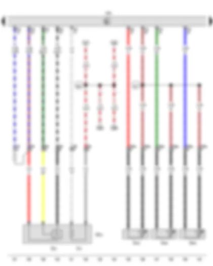
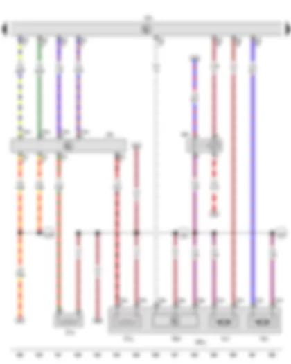
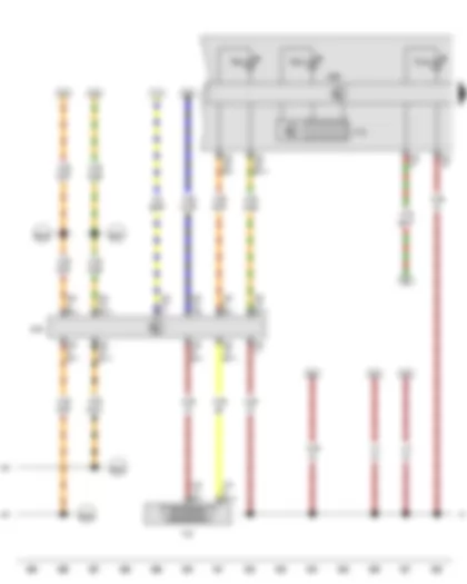
Wiring Diagram VW CADDY 2017 - Battery - Starter - Alternator - Battery monitor control unit - Onboard supply control unit - Fuse holder A - Fuse holder C

| A | Battery |
| B | Starter |
| C | Alternator |
| C1 | Voltage regulator |
| J367 | Battery monitor control unit |
| J519 | Onboard supply control unit |
| SA | Fuse holder A |
| SA1 | Fuse 1 in fuse holder A |
| SA5 | Fuse 5 in fuse holder A |
| SC | Fuse holder C |
| SC43 | Fuse 43 on fuse holder C |
| T2 | 2-pin connector, black |
| T2ai | 2-pin connector, black |
| T8o | 8-pin connector, near left headlight, black |
| T52a | 52-pin connector, black |
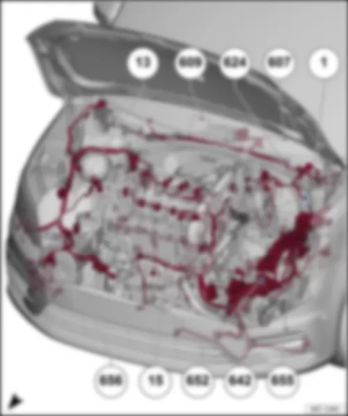
| 1 | Earth strap, battery - body |
| 508 | Threaded connection (30) on E-box |
| A209 | Connection 1 (LIN bus) in dash panel wiring harness |
| B319 | Positive connection 5 (30a) in main wiring harness |
| * | Only models with 110 A alternator |
| *2 | Only models with 140 A/ 180 A alternator |
| *3 | Only models with start/stop system |
| *4 | Only right-hand drive models |
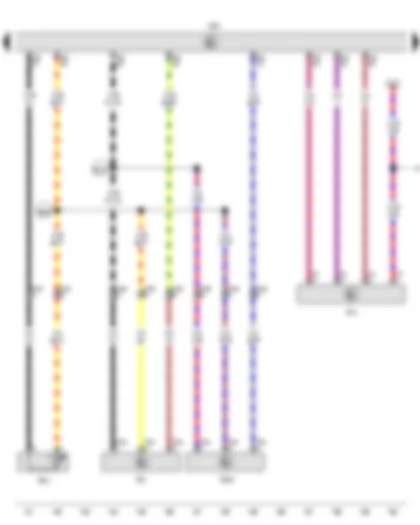
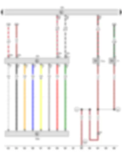
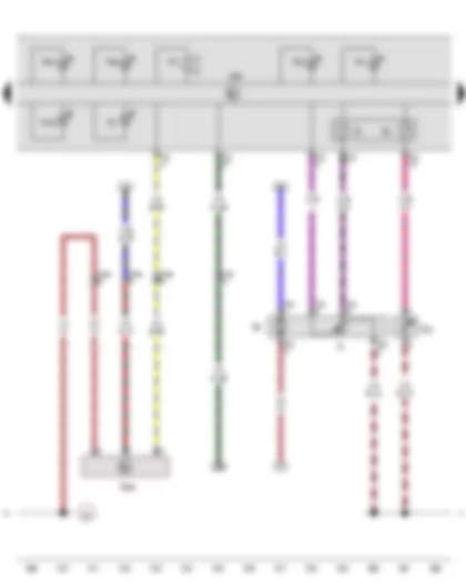
Wiring Diagram VW CADDY 2017 - Onboard supply control unit - Fuse holder C
| J519 | Onboard supply control unit |
| SC | Fuse holder C |
| SC10 | Fuse 10 on fuse holder C |
| SC13 | Fuse 13 on fuse holder C |
| SC14 | Fuse 14 on fuse holder C |
| SC16 | Fuse 16 on fuse holder C |
| SC21 | Fuse 21 on fuse holder C |
| 508 | Threaded connection (30) on E-box |
| A167 | Positive connection 3 (30a) in dash panel wiring harness |
| A192 | Positive connection 3 (15a) in dash panel wiring harness |
| A201 | Positive connection 6 (15a) in dash panel wiring harness |
| B135 | Connection 1 (15a), in interior wiring harness |
| B163 | Positive connection 1 (15), in interior wiring harness |
| * | Only models with crankcase breather heater element |
| *2 | Only models with flexible service interval display |
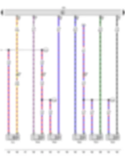
Wiring Diagram VW CADDY 2017 - Terminal 15 voltage supply relay - Onboard supply control unit - Voltage stabiliser - Starter relay 1 - Starter relay 2 - Fuse holder B
| J329 | Terminal 15 voltage supply relay |
| J519 | Onboard supply control unit |
| J532 | Voltage stabiliser |
| J906 | Starter relay 1 |
| J907 | Starter relay 2 |
| SB | Fuse holder B |
| SB7 | Fuse 7 on fuse holder B |
| SB8 | Fuse 8 on fuse holder B |
| T12c | 12-pin connector, black |
| T40 | 40-pin connector, black |
| T52b | 52-pin connector, white |
| T52c | 52-pin connector, brown |
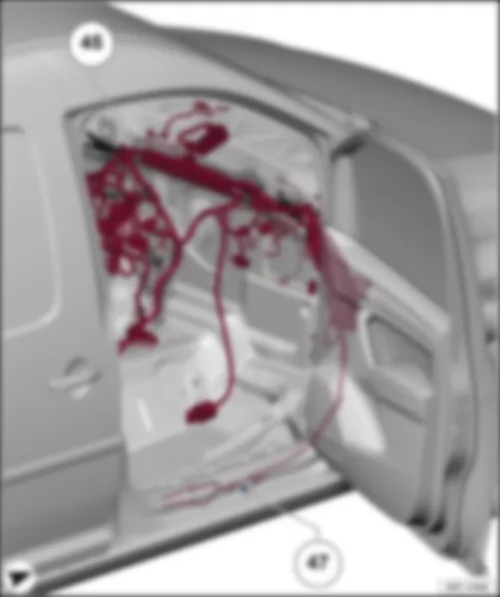
| 47 | Earth point, in front right footwell |
| 373 | Earth connection 8, in main wiring harness |
| 377 | Earth connection 12, in main wiring harness |
| 508 | Threaded connection (30) on E-box |
| B135 | Connection 1 (15a), in interior wiring harness |
| B163 | Positive connection 1 (15), in interior wiring harness |
| B660 | Connection (diagnosis terminal 50), in main wiring harness |
| * | Only right-hand drive models |
| *2 | Only left-hand drive models |
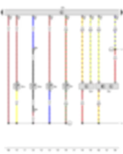
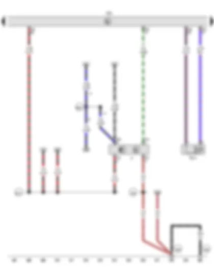
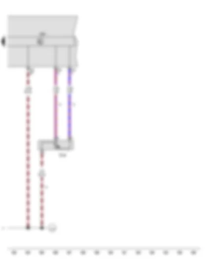
Wiring Diagram VW CADDY 2017 - Onboard supply control unit - Fuse holder B - Push-in bridge
| J519 | Onboard supply control unit |
| SB | Fuse holder B |
| SB1 | Fuse 1 on fuse holder B |
| SB3 | Fuse 3 on fuse holder B |
| SB14 | Fuse 14 on fuse holder B |
| SB15 | Fuse 15 on fuse holder B |
| SB20 | Fuse 20 on fuse holder B |
| SB23 | Fuse 23 on fuse holder B |
| SB24 | Fuse 24 on fuse holder B |
| SB27 | Fuse 27 on fuse holder B |
| TV23 | Push-in bridge |
| T40 | 40-pin connector, black |
| * | Only right-hand drive models |
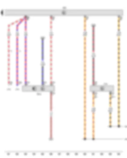
Wiring Diagram VW CADDY 2017 - Fuel pump relay - Onboard supply control unit - Fuel supply relay - Engine component current supply relay - Fuse holder B
| J17 | Fuel pump relay |
| J519 | Onboard supply control unit |
| J643 | Fuel supply relay |
| J757 | Engine component current supply relay |
| SB | Fuse holder B |
| SB10 | Fuse 10 on fuse holder B |
| SB13 | Fuse 13 on fuse holder B |
| SB21 | Fuse 21 on fuse holder B |
| SB22 | Fuse 22 on fuse holder B |
| T40 | 40-pin connector, black |
| T52b | 52-pin connector, white |
| B150 | Positive connection 2 (30a), in interior wiring harness |
| B350 | Positive connection 1 (87a) in main wiring harness |
| D78 | Positive connection 1 (30a), in engine compartment wiring harness |
| D183 | Connection 4 (87a) in engine compartment wiring harness |
| * | Only models with auxiliary heating |
| *2 | Only models with dual clutch gearbox (DSG) |
| *3 | Only models with manual gearbox |
Wiring Diagram VW CADDY 2017 - Onboard supply control unit - Steering column electronics control unit
| J519 | Onboard supply control unit |
| J527 | Steering column electronics control unit |
| T16a | 16-pin connector, black |
| T52a | 52-pin connector, black |
| T52b | 52-pin connector, white |
| T52c | 52-pin connector, brown |
| 372 | Earth connection 7, in main wiring harness |
| 375 | Earth connection 10, in main wiring harness |
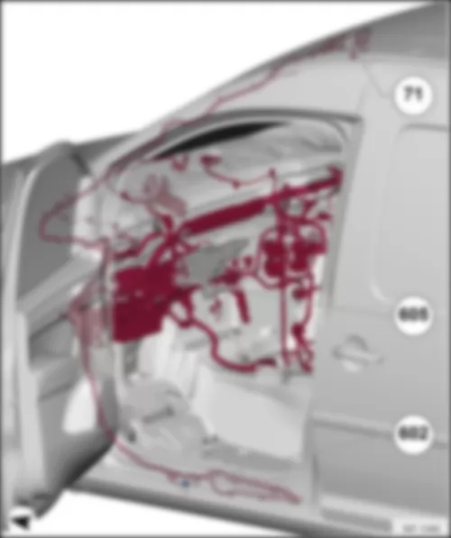
| 602 | Earth point, in front left footwell |
| 605 | Earth point, on top end of steering column |
| B273 | Positive connection (15), in main wiring harness |
| * | Only right-hand drive models |
| *2 | Only left-hand drive models |
Wiring Diagram VW CADDY 2017 - Steering column electronics control unit - Engine control unit
| J527 | Steering column electronics control unit |
| J623 | Engine control unit, central in plenum chamber |
| T16a | 16-pin connector, black |
| T94 | 94-pin connector, black |
| 131 | Earth connection 2, in engine compartment wiring harness |
| 607 | Earth point, on left in plenum chamber |
| D182 | Connection 3 (87a) in engine compartment wiring harness |
| * | Only models with manual gearbox |
Wiring Diagram VW CADDY 2017 - Cylinder 3 combustion chamber pressure sender - Automatic glow period control unit - Engine control unit - Heater element for crankcase breather - Glow plug 1 - Glow plug 2 - Glow plug 3 - Glow plug 4
| G679 | Cylinder 3 combustion chamber pressure sender |
| J179 | Automatic glow period control unit, on left under E-box |
| J623 | Engine control unit, central in plenum chamber |
| N79 | Heater element for crankcase breather |
| Q10 | Glow plug 1 |
| Q11 | Glow plug 2 |
| Q12 | Glow plug 3 |
| Q13 | Glow plug 4 |
| T4az | 4-pin connector, black |
| T11 | 11-pin connector, black, green |
| T14f | 14-pin connector, near left headlight, grey |
| T60 | 60-pin connector, black |
| T94 | 94-pin connector, black |
| 131 | Earth connection 2, in engine compartment wiring harness |
| * | Only models with crankcase breather heater element |
Wiring Diagram VW CADDY 2017 - Start/Stop operation button - Accelerator position sender - Accelerator position sender 2 - Engine control unit
| E693 | Start/Stop operation button |
| G79 | Accelerator position sender |
| G185 | Accelerator position sender 2 |
| J623 | Engine control unit, central in plenum chamber |
| K259 | Start/Stop operation warning lamp |
| L76 | Button illumination bulb |
| T6l | 6-pin connector, blue |
| T6y | 6-pin connector, black |
| T94 | 94-pin connector, black |
| A199 | Positive connection 4 (15a) in dash panel wiring harness |
| B340 | Connection 1 (58d), in main wiring harness |
Wiring Diagram VW CADDY 2017 - Lambda probe - Exhaust gas temperature sender 2 - Exhaust gas temperature sender 3 - Exhaust gas temperature sender 4 - Engine control unit
| GX10 | Lambda probe 1 before catalytic converter |
| G39 | Lambda probe |
| G448 | Exhaust gas temperature sender 2 |
| G495 | Exhaust gas temperature sender 3 |
| G648 | Exhaust gas temperature sender 4 |
| J623 | Engine control unit, central in plenum chamber |
| T2bp | 2-pin connector, in rear of engine compartment, brown |
| T2bq | 2-pin connector, in rear of engine compartment, light brown |
| T2cm | 2-pin connector, in rear of engine compartment, black |
| T6r | 6-pin connector, in rear of engine compartment, black |
| T94 | 94-pin connector, black |
| Z19 | Lambda probe heater |
| 327 | Earth connection (sender earth), in engine compartment wiring harness |
| E30 | Connection (87a), in engine wiring harness |
| * | Only models with auxiliary air heater |
Wiring Diagram VW CADDY 2017 - Charge pressure sender - Air mass meter - Exhaust gas pressure sensor 1 - Charge air temperature sender after charge air cooler - Engine control unit
| G31 | Charge pressure sender |
| G70 | Air mass meter |
| G450 | Exhaust gas pressure sensor 1 |
| G811 | Charge air temperature sender after charge air cooler |
| J623 | Engine control unit, central in plenum chamber |
| T3ai | 3-pin connector, black |
| T3bx | 3-pin connector, black |
| T4i | 4-pin connector, black |
| T10t | 10-pin connector, black |
| T14f | 14-pin connector, near left headlight, grey |
| T94 | 94-pin connector, black |
| B369 | Connection 1 (5V), in main wiring harness |
| B370 | Connection 2 (5V), in main wiring harness |
| D197 | Connection 5 (87a) in engine compartment wiring harness |
Wiring Diagram VW CADDY 2017 - Engine control unit - Charge pressure control solenoid valve - Camshaft control valve 1 - Fuel pressure regulating valve - Fuel metering valve - Valve for oil pressure control - Coolant valve for cylinder head
| J623 | Engine control unit, central in plenum chamber |
| N75 | Charge pressure control solenoid valve |
| N205 | Camshaft control valve 1 |
| N276 | Fuel pressure regulating valve |
| N290 | Fuel metering valve |
| N428 | Valve for oil pressure control |
| N489 | Coolant valve for cylinder head |
| T14f | 14-pin connector, near left headlight, grey |
| T60 | 60-pin connector, black |
| D189 | Connection (87a) in engine prewiring harness |
| D196 | Connection 2 (87a) in engine prewiring harness |
| D197 | Connection 5 (87a) in engine compartment wiring harness |
Wiring Diagram VW CADDY 2017 - Engine speed sender - Coolant temperature sender - Fuel temperature sender - Exhaust gas temperature sender 1 - Fuel pressure sender - Charge air temperature sender before charge air cooler - Engine control unit
| G28 | Engine speed sender |
| G62 | Coolant temperature sender |
| G81 | Fuel temperature sender |
| G235 | Exhaust gas temperature sender 1 |
| G247 | Fuel pressure sender |
| G810 | Charge air temperature sender before charge air cooler |
| J623 | Engine control unit, central in plenum chamber |
| T2bo | 2-pin connector, in rear of engine compartment, black |
| T60 | 60-pin connector, black |
| 220 | Earth connection (sender earth), in engine wiring harness |
| 474 | Earth connection (sender earth) in engine prewiring harness |
| D141 | Connection (5V) in engine prewiring harness |
Wiring Diagram VW CADDY 2017 - Throttle valve potentiometer - Throttle valve drive for electric throttle - Exhaust gas recirculation potentiometer 2 - Throttle valve module - Engine control unit - Exhaust gas recirculation control motor 2
| GX3 | Throttle valve module |
| GX5 | Exhaust gas recirculation valve 1 |
| GX6 | Exhaust gas recirculation valve 2 |
| G69 | Throttle valve potentiometer |
| G186 | Throttle valve drive for electric throttle |
| G212 | Exhaust gas recirculation potentiometer |
| G466 | Exhaust gas recirculation potentiometer 2 |
| J338 | Throttle valve module |
| J623 | Engine control unit, central in plenum chamber |
| T5x | 5-pin connector, black |
| T5y | 5-pin connector, black |
| T6cs | 6-pin connector, grey |
| T60 | 60-pin connector, black |
| T94 | 94-pin connector, black |
| V338 | Exhaust gas recirculation control motor |
| V339 | Exhaust gas recirculation control motor 2 |
| 220 | Earth connection (sender earth), in engine wiring harness |
| D141 | Connection (5V) in engine prewiring harness |
Wiring Diagram VW CADDY 2017 - Pressure differential sender - Gearbox neutral position sender - Engine control unit - Exhaust flap control unit
| G505 | Pressure differential sender |
| G701 | Gearbox neutral position sender |
| J623 | Engine control unit, central in plenum chamber |
| J883 | Exhaust flap control unit |
| T3aj | 3-pin connector, black, brown |
| T3by | 3-pin connector, black |
| T5w | 5-pin connector, black |
| T10t | 10-pin connector, black |
| T94 | 94-pin connector, black |
| 316 | Earth connection (sender earth 2) in engine wiring harness |
| D103 | Connection 3 in engine compartment wiring harness |
| D106 | Connection 4 in engine compartment wiring harness |
| D195 | Connection 1 (5V) in engine compartment wiring harness |
| * | Only models with manual gearbox |
Wiring Diagram VW CADDY 2017 - Hall sender - Position sender for charge pressure positioner - Engine control unit - Injector - cylinder 1 - Injector - cylinder 2 - Injector - cylinder 3 - Injector - cylinder 4
| G40 | Hall sender |
| G581 | Position sender for charge pressure positioner |
| J623 | Engine control unit, central in plenum chamber |
| N30 | Injector, cylinder 1 |
| N31 | Injector, cylinder 2 |
| N32 | Injector, cylinder 3 |
| N33 | Injector, cylinder 4 |
| T3am | 3-pin connector, black |
| T60 | 60-pin connector, black |
| 843 | Earth connection 2 (sender earth) in engine wiring harness |
| D174 | Connection 2 (5V) in engine prewiring harness |
Wiring Diagram VW CADDY 2017 - Engine control unit - Charge air cooling pump - Auxiliary pump for heating
| E16 | Heater/heat output switch |
| J359 | Low heat output relay |
| J360 | High heat output relay |
| J623 | Engine control unit, central in plenum chamber |
| T4x | 4-pin connector, on radiator fan, bottom left, black |
| T8o | 8-pin connector, near left headlight, black |
| T10s | 10-pin connector, near left headlight, black |
| T10t | 10-pin connector, black |
| T20c | 20-pin connector, black |
| T60 | 60-pin connector, black |
| T94 | 94-pin connector, black |
| V188 | Charge air cooling pump |
| V488 | Auxiliary pump for heating |
| D180 | Connection (87a), in engine compartment wiring harness |
| * | Radiator fan connection |
| *2 | Only models with no air conditioning system |
| *3 | Only models with auxiliary air heater |
Wiring Diagram VW CADDY 2017 - Delivery unit for reducing agent metering system - Reducing agent level sender - Engine control unit - Control unit for reducing-agent heater - Relay for reducing agent metering system - Pump for reducing agent - Reducing agent return flow pump - Heater for reducing-agent tank (heater circuit 1) - Heater for reducing-agent line (heater circuit 2)
| GX19 | Delivery unit for reducing agent metering system, front left in engine compartment |
| G697 | Reducing agent level sender |
| J623 | Engine control unit, central in plenum chamber |
| J891 | Control unit for reducing-agent heater, on right in plenum chamber |
| J963 | Relay for reducing agent metering system |
| T4ba | 4-pin connector, black |
| T4bb | 4-pin connector, black |
| T5aa | 5-pin connector, black |
| T5z | 5-pin connector, black |
| T94 | 94-pin connector, black |
| V437 | Pump for reducing agent |
| V561 | Reducing agent return flow pump |
| Z102 | Heater for reducing-agent tank (heater circuit 1) |
| Z104 | Heater for reducing-agent line (heater circuit 2) |
| 363 | Earth connection 8, in engine compartment wiring harness |
| D188 | Positive connection 3 (30a), in engine compartment wiring harness |
| E78 | Connection 2 (87a) in engine wiring harness |
Wiring Diagram VW CADDY 2017 - Oil pressure switch - Oil pressure switch for reduced oil pressure - NOx sender - Control unit for NOx sender - Engine control unit
| F1 | Oil pressure switch |
| F378 | Oil pressure switch for reduced oil pressure |
| G295 | NOx sender |
| J583 | Control unit for NOx sender, on left in engine compartment |
| J623 | Engine control unit, central in plenum chamber |
| T5ab | 5-pin connector, black |
| T8j | 8-pin connector, black |
| T14f | 14-pin connector, near left headlight, grey |
| T60 | 60-pin connector, black |
| T94 | 94-pin connector, black |
| 281 | Earth point 1, engine prewiring harness |
| 317 | Earth connection 7, in engine compartment wiring harness |
| 640 | Earth point 2, left in engine compartment |
| * | Sheathed cable, black |
Wiring Diagram VW CADDY 2017 - Brake light switch - Engine control unit - Injector for reducing agent
| F | Brake light switch |
| J623 | Engine control unit, central in plenum chamber |
| N474 | Injector for reducing agent |
| T4w | 4-pin connector, black |
| T94 | 94-pin connector, black |
| 209 | Earth connection 6, in engine compartment wiring harness |
| 652 | Earth point, engine and gearbox earth |
| 655 | Earth point, on left headlight |
| B131 | Connection (54), in interior wiring harness |
| B351 | Positive connection 2 (87a) in main wiring harness |
| * | Only models with dual clutch gearbox (DSG) |
| *2 | Only models with manual gearbox |
Wiring Diagram VW CADDY 2017 - Clutch position sender - Engine control unit
| G476 | Clutch position sender |
| J104 | ABS control unit |
| J623 | Engine control unit, central in plenum chamber |
| J743 | Mechatronic unit for dual clutch gearbox |
| T5m | 5-pin connector, black |
| T20e | 20-pin connector, black |
| T25 | 25-pin connector, black |
| T38 | 38-pin connector, brown |
| T94 | 94-pin connector, black |
| B383 | Connection 1 (powertrain CAN bus, high), in main wiring harness |
| B390 | Connection 1 (powertrain CAN bus, low), in main wiring harness |
| * | Only models with manual gearbox |
| *2 | Only models with dual clutch gearbox 02E |
| *3 | Only models with dual clutch gearbox 0AM |
Wiring Diagram VW CADDY 2017 - Multifunction indicator - Control unit in dash panel insert - Data bus diagnostic interface - Diagnostic connection
| J119 | Multifunction indicator |
| J285 | Control unit in dash panel insert |
| J533 | Data bus diagnostic interface |
| K83 | Exhaust emissions warning lamp |
| K132 | Electronic power control fault lamp |
| K327 | Reducing agent level warning lamp |
| T16 | 16-pin connector, purple |
| T20 | 20-pin connector, red |
| T32 | 32-pin connector, blue |
| U31 | Diagnostic connection |
| 367 | Earth connection 2, in main wiring harness |
| B383 | Connection 1 (powertrain CAN bus, high), in main wiring harness |
| B390 | Connection 1 (powertrain CAN bus, low), in main wiring harness |
| B397 | Connection 1 (convenience CAN bus, high), in main wiring harness |
| B406 | Connection 1 (convenience CAN bus, low), in main wiring harness |
Wiring Diagram VW CADDY 2017 - Fuel gauge sender - Fuel gauge - Coolant temperature gauge - Fuel system pressurisation pump - Coolant shortage indicator sender - Oil level and oil temperature sender - Control unit in dash panel insert - Glow period warning lamp - Diesel particulate filter warning lamp
| G | Fuel gauge sender |
| G1 | Fuel gauge |
| G3 | Coolant temperature gauge |
| G6 | Fuel system pressurisation pump |
| G32 | Coolant shortage indicator sender |
| G266 | Oil level and oil temperature sender |
| H3 | Buzzer and gong |
| J285 | Control unit in dash panel insert |
| K3 | Oil pressure warning lamp |
| K29 | Glow period warning lamp |
| K31 | Cruise control system warning lamp |
| K38 | Oil level warning lamp |
| K105 | Reserve fuel warning lamp |
| K231 | Diesel particulate filter warning lamp |
| T5a | 5-pin connector, black |
| T10s | 10-pin connector, near left headlight, black |
| T14f | 14-pin connector, near left headlight, grey |
| T32 | 32-pin connector, blue |
| 367 | Earth connection 2, in main wiring harness |
| 410 | Earth connection 1 (sender earth) in main wiring harness |
| * | Only models with flexible service interval display |
Wiring Diagram VW CADDY 2017 - Fuel gauge sender 2 - Control unit in dash panel insert
| G169 | Fuel gauge sender 2 |
| J285 | Control unit in dash panel insert |
| T32 | 32-pin connector, blue |
| 410 | Earth connection 1 (sender earth) in main wiring harness |
| * | see applicable current flow diagram for all-wheel drive |
| *2 | Only models with all-wheel drive |
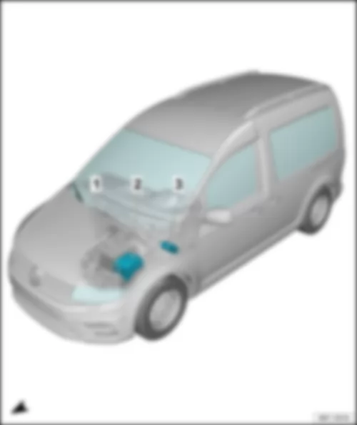
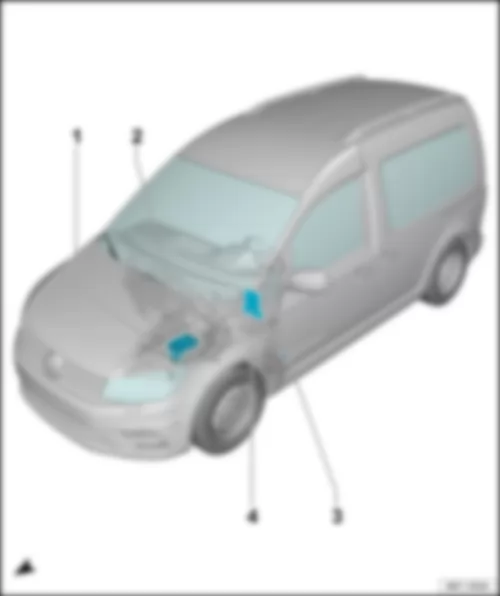
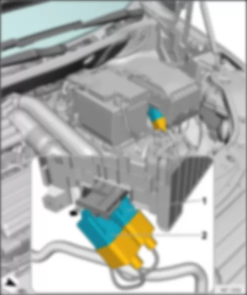
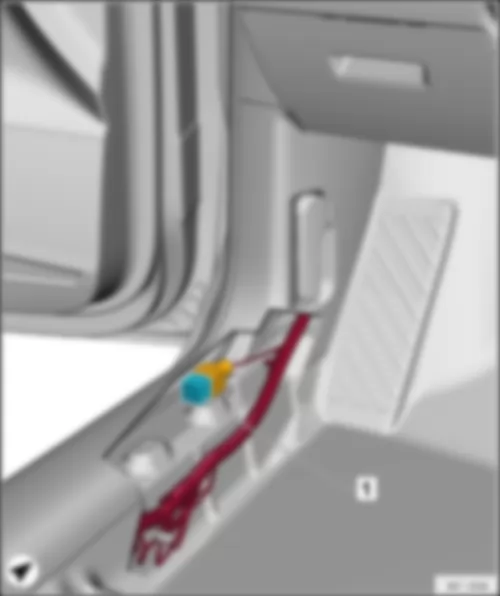
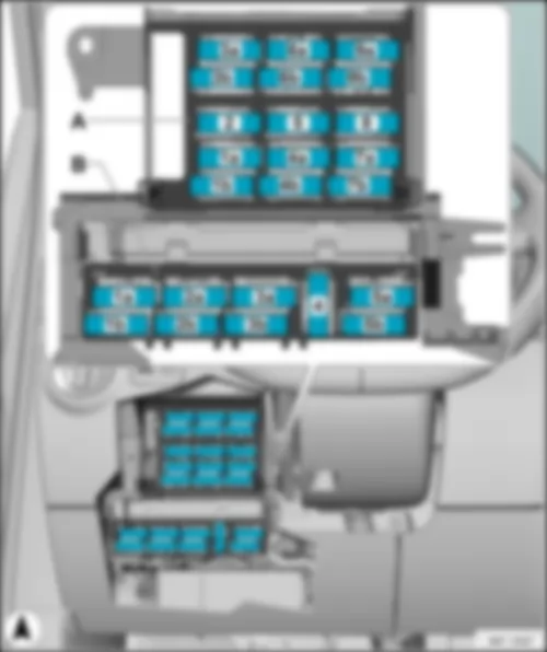
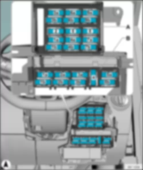
VW CADDY 2017 Overview of fuses
| Overview of fuses |
| 1 - | Fuses (SA) on fuse holder A |
| q | Fitting location → Chapter |
| q | Fuse assignment, from June 2015 → Chapter |
| 2 - | Fuses (SB) on fuse holder B |
| q | Fitting location → Chapter |
| q | Fuse assignment, from June 2015 → Chapter |
| 3 - | Fuses (SC) on fuse holder C |
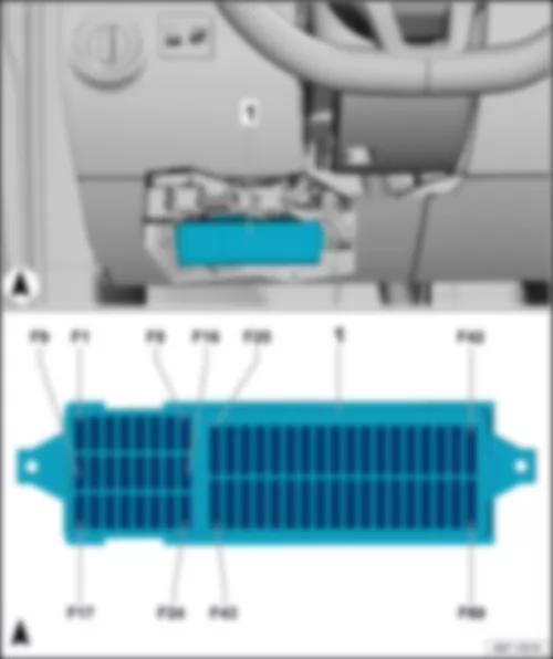
| q | Fitting location left-hand drive → Chapter |
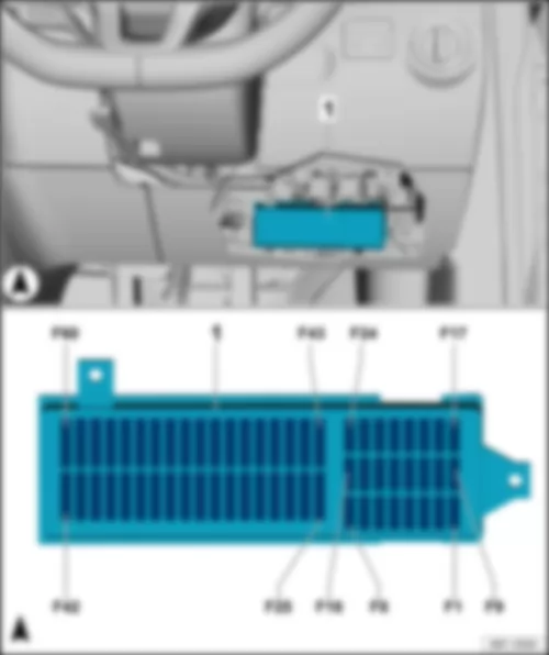
| q | Fitting location right-hand drive → Chapter |
| q | Fuse assignment, from June 2015 → Chapter |
|
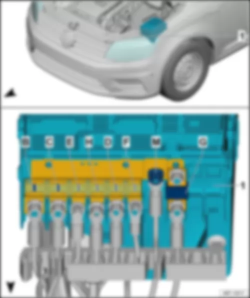
| 1 - | Fuse holder A -SA- |
| Fuse colours for MIDI strip fuse: |
| t | 200 A - purple |
| t | 150 A - grey |
| t | 125 A - pink |
| t | 100 A - blue |
| t | 80 A - white / transparent |
| t | 70 A - brown |
| t | 60 A - yellow |
| t | 50 A - red |
| t | 40 A - green |
| t | 30 A - orange |
Note:
|
| Fuse assignment in fuse holder A, from June 2015 |
| Item | Wiring diagram designation | Nominal value | Function/ component | Terminal | ||||||
| B | - | Fuse 1 on fuse holder A -SA1- | 200 A | - | Alternator -C- , with 110 A | 30 | ||||
| 400 A | - | Alternator -C- , with 140 A/ 180 A | 30 | |||||||
| C | - | Fuse 2 on fuse holder A -SA2- | 80 A | - | Power steering control unit -J500-
| 30 | ||||
| E | - | Fuse 3 on fuse holder A -SA3- | 50 A | - | Radiator fan control unit -J293-
| 30 | ||||
| H | - | Fuse 4 on fuse holder A -SA4- | 80 A | - | X-contact relief relay -J59-1)
| 30 | ||||
| D | - | Fuse 5 on fuse holder A -SA5- | 80 A | - | Fuse holder C -SC- (-SC20- to -SC24- and -SC43- to -SC53- ) | 30 | ||||
| F | - | Fuse 6 on fuse holder A -SA6- | 40 A | - | Low heat output relay -J359-
| 30 | ||||
| M | - | Threaded connection (30) on E-box -508- | - | Fuse holder A -SA- Fuse holder B -SB- | 30 | |||||
| G | - | Fuse 7 on fuse holder A -SA7- | 80 A | - | High heat output relay -J360-
| 30 |
| t | 1) Only models with Climatronic |
|
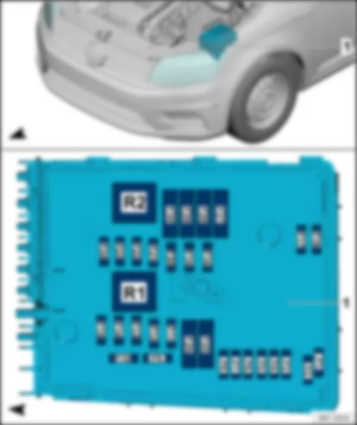
| 1 - | Fuse holder B -SB- |
| Fuse colours for ATO flat fuse: |
| t | 40 A - orange |
| t | 35 A - green-blue |
| t | 30 A - light green |
| t | 25 A - transparent |
| t | 20 A - yellow |
| t | 15 A - light blue |
| t | 10 A - red |
| t | 7.5 A - brown |
| t | 5 A - light brown |
| t | 1 A - black |
| Fuse colours for Maxi ATO flat fuse: |
| t | 60 A - blue |
| t | 50 A - red |
| t | 40 A - orange |
| t | 30 A - light green |
| t | 20 A - yellow |
|
| Fuse assignment on fuse holder B, from June 2015 |
| Item | Wiring diagram designation | Nominal value | Function/ component | Terminal | ||||||||||||||||||||||||||||||
| F1 | - | Fuse 1 on fuse holder B -SB1- | 30 A | - | Control unit for reducing-agent heater -J891- | 30 | ||||||||||||||||||||||||||||
| F2 | - | Fuse 2 on fuse holder B -SB2- | 30 A | - | Mechatronics unit for dual clutch gearbox -J743- | 30 | ||||||||||||||||||||||||||||
| F3 | - | Fuse 3 on fuse holder B -SB3- | 5 A | - | Battery monitor control unit -J367- Onboard supply control unit -J519- (T52a/24) | 30 | ||||||||||||||||||||||||||||
| F4 | - | Fuse 4 on fuse holder B -SB4- | 20 A | - | ABS control unit -J104- ABS hydraulic unit -N55- | 30 | ||||||||||||||||||||||||||||
| F5 | - | Fuse 5 on fuse holder B -SB5- | 15 A | - | Mechatronics unit for dual clutch gearbox -J743- | 30 | ||||||||||||||||||||||||||||
| F6 | - | Fuse 6 on fuse holder B -SB6- | 5 A | - | Control unit in dash panel insert -J285-2) Steering column electronics control unit -J527-2) | 30 | ||||||||||||||||||||||||||||
| F7 | - | Fuse 7 on fuse holder B -SB7- | 40 A | - | Terminal 15 voltage supply relay -J329-
| 30 | ||||||||||||||||||||||||||||
| F8 | - | Fuse 8 on fuse holder B -SB8- | 15 A | - | Control unit with display for radio and navigation -J503-2) Control unit 1 for information electronics -J794-2) Radio -R-2) USB hub -R293-2) Voltage stabiliser -J532-1)
| 30 | ||||||||||||||||||||||||||||
| F9 | - | Fuse 9 on fuse holder B -SB9- | 20 A | - | All-wheel drive control unit -J492- | 30 | ||||||||||||||||||||||||||||
| F10 | - | Fuse 10 on fuse holder B -SB10- | 5 A | - | Engine control unit -J623- Engine component current supply relay -J757- | 30 | ||||||||||||||||||||||||||||
| F11 | - | Fuse 11 on fuse holder B -SB11- | 20 A | - | Auxiliary heater control unit -J364- | 30 | ||||||||||||||||||||||||||||
| F12 | - | Fuse 12 on fuse holder B -SB12- | 5 A | - | Data bus diagnostic interface -J533- | 30 | ||||||||||||||||||||||||||||
| F13 | - | Fuse 13 on fuse holder B -SB13- | 15 A | - | Engine control unit -J623- (petrol engine) | 87 | ||||||||||||||||||||||||||||
| 30 A | - | Engine control unit -J623- (diesel) | 87 | |||||||||||||||||||||||||||||||
| F14 | - | Fuse 14 on fuse holder B -SB14- | 10 A | - | Camshaft control valve 1 -N205- (diesel with exhaust standard Euro 6) Fuel pressure regulating valve -N276- (diesel with exhaust standard Euro 6) Fuel metering valve -N290- (diesel with exhaust standard Euro 6) | 87 | ||||||||||||||||||||||||||||
| 15 A | - | Fuel pressure regulating valve -N276- (diesel with exhaust standard Euro 5, Euro 4) Fuel metering valve -N290- (diesel with exhaust standard Euro 5, Euro 4) | 87 | |||||||||||||||||||||||||||||||
| 20 A | - | Ignition transformer -N152- Ignition coil 1 with output stage -N70- Ignition coil 2 with output stage -N127- Ignition coil 3 with output stage -N291- Ignition coil 4 with output stage -N292- | 87 | |||||||||||||||||||||||||||||||
| F15 | - | Fuse 15 on fuse holder B -SB15- | 5 A | - | Fuel pump relay -J17- Electric fuel pump 2 relay -J49- Automatic glow period control unit -J179- | 87 | ||||||||||||||||||||||||||||
| 10 A | - | Lambda probe heater -Z19- Lambda probe 1 heater after catalytic converter -Z29- | 87 | |||||||||||||||||||||||||||||||
| 15 A | - | Low heat output relay -J359- High heat output relay -J360- Control unit for NOx sender -J583- Lambda probe heater -Z19- | 87 | |||||||||||||||||||||||||||||||
| F16 | - | Fuse 16 on fuse holder B -SB16- | 30 A | - | Onboard supply control unit -J519- (T52c/42)
| 30 | ||||||||||||||||||||||||||||
| F17 | - | Fuse 17 on fuse holder B -SB17- | 15 A | - | Horn relay -J413-
| 30 | ||||||||||||||||||||||||||||
| F18 | - | Fuse 18 on fuse holder B -SB18- | 30 A | - | Special vehicle control unit -J608- | 30 | ||||||||||||||||||||||||||||
| F19 | - | Fuse 19 on fuse holder B -SB19- | 30 A | - | Wiper motor control unit -J400-
| 30 | ||||||||||||||||||||||||||||
| F20 | - | Fuse 20 on fuse holder B -SB20- | 10 A | - | Fuel tank shut-off valve 1 -N361- Fuel tank shut-off valve 2 -N362- Fuel tank shut-off valve 3 -N363- Fuel tank shut-off valve 4 -N429- Fuel tank shut-off valve 5 -N430- | 30 | ||||||||||||||||||||||||||||
| F21 | - | Fuse 21 on fuse holder B -SB21- | 10 A | - | Fuel pump relay -J17- (diesel with exhaust standard Euro 6) Automatic glow period control unit -J179- (diesel with exhaust standard Euro 6) Low heat output relay -J359- (diesel with exhaust standard Euro 5, Euro 4) High heat output relay -J360- (diesel with exhaust standard Euro 5, Euro 4) Lambda probe heater -Z19- (diesel with exhaust standard Euro 5, Euro 4) | 30 | ||||||||||||||||||||||||||||
| 15 A | - | Fuel pump control unit -J538- (petrol engine) | 87 | |||||||||||||||||||||||||||||||
| F22 | - | Fuse 22 on fuse holder B -SB22- | 5 A | - | Brake light switch -F- Clutch position sender -G476- | 87 | ||||||||||||||||||||||||||||
| F23 | - | Fuse 23 on fuse holder B -SB23- | 10 A | - | Air mass meter -G70- Charge pressure control solenoid valve -N75- Exhaust gas recirculation cooler changeover valve -N345- Valve for oil pressure control -N428- Coolant valve for cylinder head -N489- | 87 | ||||||||||||||||||||||||||||
| 15 A | - | Additional coolant pump relay -J496- High-pressure valve for gas mode -N372- Charge air cooling pump -V188- | 87 | |||||||||||||||||||||||||||||||
| F24 | - | Fuse 24 on fuse holder B -SB24- | 10 A | - | Radiator fan control unit -J293- Relay for reducing agent metering system -J963-
Camshaft control valve 1 -N205- Gas injection valve 1 -N366- Gas injection valve 2 -N367- Gas injection valve 3 -N368- Gas injection valve 4 -N369- Valve for oil pressure control -N428- Coolant circulation pump 2 -V178- Charge air cooling pump -V188- Heater support pump -V488- | 87 | ||||||||||||||||||||||||||||
| F25 | - | Fuse 25 on fuse holder B -SB25- | 40 A | - | ABS control unit -J104- ABS hydraulic pump -V64- | 30 | ||||||||||||||||||||||||||||
| F26 | - | Fuse 26 on fuse holder B -SB26- | 30 A | - | Onboard supply control unit -J519- (T52a/1)
| 30 | ||||||||||||||||||||||||||||
| F27 | - | Fuse 27 on fuse holder B -SB27- | 50 A | - | Automatic glow period control unit -J179- | 30 | ||||||||||||||||||||||||||||
| F28 | - | Fuse 28 on fuse holder B -SB28- | 40 A | - | Fuse 56 on fuse holder C -SC56-
| 30 | ||||||||||||||||||||||||||||
| 60 A | - | Heated windscreen relay -J47-
| 30 | |||||||||||||||||||||||||||||||
| F29 | - | Fuse 29 on fuse holder B -SB29- | 30 A | - | Special vehicles
| 30 | ||||||||||||||||||||||||||||
| 50 A | - | Special vehicles
| 30 | |||||||||||||||||||||||||||||||
| F30 | - | Fuse 30 on fuse holder B -SB30- | 50 A | - | Trailer coupling
| 30 |
| t | 1) Only models with start/stop system |
| t | 2) Only models with no start/stop system |
|
| 1 - | Fuse holder C -SC- |
| Fuse colours for ATO flat fuse: |
| t | 40 A - orange |
| t | 35 A - green-blue |
| t | 30 A - light green |
| t | 25 A - transparent |
| t | 20 A - yellow |
| t | 15 A - light blue |
| t | 10 A - red |
| t | 7.5 A - brown |
| t | 5 A - light brown |
| t | 1 A - black |
|
| Fuse assignment on fuse holder C, from June 2015 |
| Item | Wiring diagram designation | Nominal value | Function/ component | Terminal | ||||||||||||
| 1 | - | Fuse 1 on fuse holder C -SC1- | - | |||||||||||||
| 2 | - | Fuse 2 on fuse holder C -SC2- | - | |||||||||||||
| 3 | - | Fuse 3 on fuse holder C -SC3- | - | |||||||||||||
| 4 | - | Fuse 4 on fuse holder C -SC4- | - | |||||||||||||
| 5 | - | Fuse 5 on fuse holder C -SC5- | - | |||||||||||||
| 6 | - | Fuse 6 on fuse holder C -SC6- | - | |||||||||||||
| 7 | - | Fuse 7 on fuse holder C -SC7- | - | |||||||||||||
| 8 | - | Fuse 8 on fuse holder C -SC8- | - | |||||||||||||
| 9 | - | Fuse 9 on fuse holder C -SC9- | 10 A | - | Special vehicles
| 15a | ||||||||||
| 10 | - | Fuse 10 on fuse holder C -SC10- | 5 A | - | Voltage stabiliser -J532- Data bus diagnostic interface -J533- Engine control unit -J623- Starter relay 1 -J906- Starter relay 2 -J907- | 15a | ||||||||||
| 11 | - | Fuse 11 on fuse holder C -SC11- | 5 A | - | Parking aid control unit -J446- Park assist steering control unit -J791- | 15a | ||||||||||
| 12 | - | Fuse 12 on fuse holder C -SC12- | 5 A | - | Special vehicles
| 15a | ||||||||||
| 20 A | - | Special vehicles
| 15a | |||||||||||||
| 13 | - | Fuse 13 on fuse holder C -SC13- | 7.5 A | - | Headlight range control regulator -E102- Button for TCS and electronic stabilisation program -E256- Selector lever -E313- Tyre pressure loss indicator button -E492- Start/Stop operation button -E693- ABS control unit -J104- Trailer detector control unit -J345- Adaptive cruise control unit -J428- All-wheel drive control unit -J492- Power steering control unit -J500- Mechatronics unit for dual clutch gearbox -J743- DC/AC converter with socket, 12 V-230 V -U13- Left headlight range control motor -V48- Right headlight range control motor -V49- | 15a | ||||||||||
| 14 | - | Fuse 14 on fuse holder C -SC14- | 10 A | - | Reversing light switch -F4- Air mass meter -G70- Auxiliary heater operation relay -J485- Control unit in dash panel insert -J285- Heater element for crankcase breather -N79- Diagnostic connection -U31-Connector, 16-pin -T16- , Pin 1 | 15a | ||||||||||
| 15 | - | Fuse 15 on fuse holder C -SC15- | 5 A | - | Airbag control unit -J234- Front passenger airbag deactivated warning lamp -K145- | 15a | ||||||||||
| 16 | - | Fuse 16 on fuse holder C -SC16- | 5 A | - | Light switch -E1- Heater/heat output switch -E16- High-pressure sender -G65- Air quality sensor -G238- Oil level and oil temperature sender -G266- Automatic anti-dazzle interior mirror -Y7- | 15a | ||||||||||
| 17 | - | Fuse 17 on fuse holder C -SC17- | - | |||||||||||||
| 18 | - | Fuse 18 on fuse holder C -SC18- | 5 A | - | Special vehicles
| 30a | ||||||||||
| 10 A | - | Special vehicles
| BLL | |||||||||||||
| 19 | - | Fuse 19 on fuse holder C -SC19- | 10 A | - | Special vehicles
| 30a | ||||||||||
| 10 A | - | Special vehicles
| BLR | |||||||||||||
| 20 | - | Fuse 20 on fuse holder C -SC20- | 20 A | - | Cigarette lighter -U1- | 30a | ||||||||||
| 21 | - | Fuse 21 on fuse holder C -SC21- | 10 A | - | Light switch -E1- Heater/heat output switch -E16- Interior illumination switch -E599- (camper) Selector lever -E313- Rain and light sensor -G397- Heated rear window relay -J9- Heated windscreen relay -J47- Climatronic control unit -J255- A/C control module -J301- Horn relay -J413- Relay for reducing agent metering system -J963- 2-way signal amplifier for mobile radio -J984- Radio receiver for auxiliary water heater -R149- Rearview camera -R189- Coupling antenna for Bluetooth mobile phone -R309- Diagnostic connection -U31-Connector, 16-pin -T16- , Pin 16 Rear interior light -W43- (camper) | 30a | ||||||||||
| 22 | - | Fuse 22 on fuse holder C -SC22- | 10 A | - | Onboard supply control unit -J519- (T52b/42)
| 30a | ||||||||||
| 23 | - | Fuse 23 on fuse holder C -SC23- | 5 A | - | Special vehicles
| 30a | ||||||||||
| 10 A | - | Special vehicles
| 30a | |||||||||||||
| 24 | - | Fuse 24 on fuse holder C -SC24- | 5 A | - | Interior monitoring sensor -G273- Vehicle inclination sender -G384- Anti-theft alarm sensor -G578- Alarm horn -H12- Onboard supply control unit -J519- (T52c/1) | 30a | ||||||||||
| 25 | - | Fuse 25 on fuse holder C -SC25- | 5 A | - | Control unit in dash panel insert -J285- | 15a | ||||||||||
| 26 | - | Fuse 26 on fuse holder C -SC26- | - | 15a | ||||||||||||
| 27 | - | Fuse 27 on fuse holder C -SC27- | - | 15a | ||||||||||||
| 28 | - | Fuse 28 on fuse holder C -SC28- | 20 A | - | 12 V socket 3 -U19- , in storage compartment | 75a | ||||||||||
| 29 | - | Fuse 29 on fuse holder C -SC29- | 15 A | - | Rear window wiper motor -V12- | 75a | ||||||||||
| 30 | - | Fuse 30 on fuse holder C -SC30- | - | 75a | ||||||||||||
| 31 | - | Fuse 31 on fuse holder C -SC31- | 5 A | - | Heater/heat output switch -E16- Left washer jet heater element -Z20- Right washer jet heater element -Z21- | 75a | ||||||||||
| 32 | - | Fuse 32 on fuse holder C -SC32- | - | 75a | ||||||||||||
| 33 | - | Fuse 33 on fuse holder C -SC33- | 30 A | - | Auxiliary heater operation relay -J485- (vehicles with auxiliary heater)
| 75a | ||||||||||
| 34 | - | Fuse 34 on fuse holder C -SC34- | - | |||||||||||||
| 35 | - | Fuse 35 on fuse holder C -SC35- | - | |||||||||||||
| 36 | - | Fuse 36 on fuse holder C -SC36- | - | |||||||||||||
| 37 | - | Fuse 37 on fuse holder C -SC37- | - | |||||||||||||
| 38 | - | Fuse 38 on fuse holder C -SC38- | - | |||||||||||||
| 39 | - | Fuse 39 on fuse holder C -SC39- | 30 A | - | Special vehicles
| 30a | ||||||||||
| 40 | - | Fuse 40 on fuse holder C -SC40- | 20 A | - | Trailer detector control unit -J345- | 30a | ||||||||||
| 41 | - | Fuse 41 on fuse holder C -SC41- | 20 A | - | Trailer detector control unit -J345- | 30a | ||||||||||
| 42 | - | Fuse 42 on fuse holder C -SC42- | 20 A | - | Trailer detector control unit -J345- | 30a | ||||||||||
| 43 | - | Fuse 43 on fuse holder C -SC43- | 15 A | - | Fuel pump relay -J17- Fuel supply relay -J49- Electric fuel pump 2 relay -J643- | 30a | ||||||||||
| 20 A | - | Fuel pump relay -J17- (diesel with exhaust standard Euro 6) Electric fuel pump 2 relay -J643- (diesel with exhaust standard Euro 6) | 30a | |||||||||||||
| 44 | - | Fuse 44 on fuse holder C -SC44- | 40 A | - | Fresh air blower control unit -J126-
| 30a | ||||||||||
| 45 | - | Fuse 45 on fuse holder C -SC45- | 20 A | - | Headlight washer system relay -J39-
| 30a | ||||||||||
| 46 | - | Fuse 46 on fuse holder C -SC46- | 10 A | - | Driver door control unit -J386- (convenience system without electric window regulators) | 30a | ||||||||||
| 30 A | - | Driver door control unit -J386- (convenience system with electric window regulators) | 30a | |||||||||||||
| 47 | - | Fuse 47 on fuse holder C -SC47- | 40 A | - | X-contact relief relay -J59-2)
| 30a | ||||||||||
| 48 | - | Fuse 48 on fuse holder C -SC48- | 30 A | - | Heated front seats control unit -J774- | 30a | ||||||||||
| 49 | - | Fuse 49 on fuse holder C -SC49- | 10 A | - | Front passenger door control unit -J387- (convenience system without electric window regulators) | 30a | ||||||||||
| 30 A | - | Front passenger door control unit -J387- (convenience system with electric window regulators) | 30a | |||||||||||||
| 50 | - | Fuse 50 on fuse holder C -SC50- | 20 A | - | Onboard supply control unit -J519-
| 30a | ||||||||||
| 51 | - | Fuse 51 on fuse holder C -SC51- | 15 A | - | Trailer voltage supply relay -J941-
| 30a | ||||||||||
| - | 30 A | - | Special vehicles
| 30a | ||||||||||||
| 52 | - | Fuse 52 on fuse holder C -SC52- | 25 A | - | Heated rear window relay -J9-
| 30a | ||||||||||
| 53 | - | Fuse 53 on fuse holder C -SC53- | 20 A | - | 12 V socket -U5- , in rear centre console 12 V socket 2 -U18- , in rear left side panel | 30a | ||||||||||
| 54 | - | Fuse 54 on fuse holder C -SC54- | 15 A | - | Special vehicles
| 30a | ||||||||||
| 55 | - | Fuse 55 on fuse holder C -SC55- | 15 A | - | Special vehicles
| 30a | ||||||||||
| 56 | - | Fuse 56 on fuse holder C -SC56- | 30 A | - | DC/AC converter with socket, 12 V - 230 V -U13- | 30a | ||||||||||
| 57 | - | Fuse 57 on fuse holder C -SC57- | 5 A | - | Control unit in dash panel insert -J285-1) Steering column electronics control unit -J527-1) | 30a | ||||||||||
| 58 | - | - | ||||||||||||||
| 59 | - | Fuse 59 on fuse holder C -SC59- | 5 A | - | Special vehicles
| 30a | ||||||||||
| 60 | - | Fuse 60 on fuse holder C -SC60- | 30 A | - | Special vehicles
| 30a |
| t | 1) Only models with start/stop system |
| t | 2) Only models with Climatronic |
|

 Deutsch
 English
 English
 Español
 Français
 Nederlands

