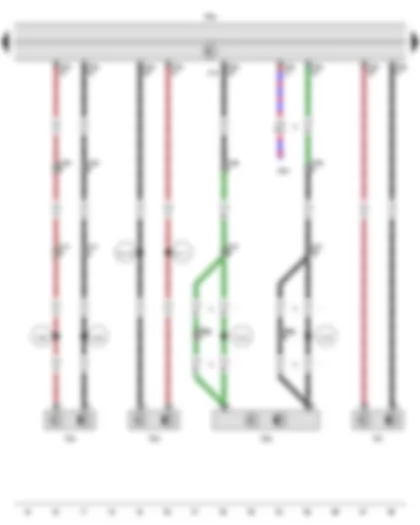
| A | Battery |
| F | Brake light switch |
| G294 | Brake servo pressure sensor |
| J104 | ABS control unit |
| J187 | Differential lock control unit |
| J623 | Engine control unit |
| N55 | ABS hydraulic unit |
| SA | Fuse holder A |
| SA4 | Fuse 4 in fuse holder A |
| SA5 | Fuse 5 in fuse holder A |
| SB6 | Fuse 6 on fuse holder B, in E-box |
| SB16 | Fuse 16 on fuse holder B |
| T3c | 3-pin connector, black |
| T10 | 10-pin connector, black, in E-box in engine compartment |
| T10f | 10-pin connector, green, in E-box in engine compartment |
| T38a | 38-pin connector, black |
| 12 | Earth point, on left in engine compartment |
| 14 | Earth point, on gearbox |
| 131 | Earth connection 2, in engine compartment wiring harness |
| 624 | Earth point, starter battery |
| 640 | Earth point 2, left in engine compartment |
| B131 | Connection (54), in interior wiring harness |
| D50 | Positive connection (30), in engine compartment wiring harness |
| * | see applicable current flow diagram for engine |
| *2 | Only models with start/stop system |
| *3 | Only models with petrol engine |
| *4 | Only models with rear differential lock |
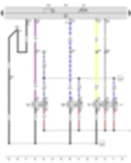
| G44 | Rear right speed sensor |
| G45 | Front right speed sensor |
| G46 | Rear left speed sensor |
| G47 | Front left speed sensor |
| J104 | ABS control unit |
| J500 | Power steering control unit |
| N55 | ABS hydraulic unit |
| T8ag | 8-pin connector, black, behind lower section of left D-pillar trim |
| T10k | 10-pin connector, purple, in E-box in engine compartment |
| T17f | 17-pin connector, brown, under driver seat |
| T38a | 38-pin connector, black |
| D111 | Connection 9 in engine compartment wiring harness |
| D112 | Connection 10 in engine compartment wiring harness |
| W23 | Connection 1 (sensor), in rear wiring harness |
| W24 | Connection 2 (sensor), in rear wiring harness |
| W75 | Connection 3 (sensor), in rear wiring harness |
| W76 | Connection 4 (sensor), in rear wiring harness |
| * | Only models with double cab/ dropside and models with no all-wheel drive |
| *2 | Only models with power assisted steering |
| *3 | Only models with all-wheel drive, not for models with double cab/ dropside |
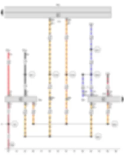
| E256 | Button for TCS and electronic stabilisation program |
| E492 | Tyre Pressure Loss Indicator button |
| E618 | Hill descent control button |
| G201 | Brake pressure sender 1 |
| J104 | ABS control unit |
| K250 | Warning lamp for hill descent control |
| L76 | Button illumination bulb |
| N55 | ABS hydraulic unit |
| SB17 | Fuse 17 on fuse holder B |
| T6e | 6-pin connector, red |
| T6f | 6-pin connector, red |
| T6g | 6-pin connector, black |
| T10k | 10-pin connector, purple, in E-box in engine compartment |
| T38a | 38-pin connector, black |
| V64 | ABS hydraulic pump |
| 368 | Earth connection 3, in main wiring harness |
| B282 | Positive connection 6 (15a) in main wiring harness |
| B342 | Connection 3 (58d), in main wiring harness |
| * | According to equipment |
| *2 | Only models with electronic stabilisation program (ESP) and traction control system (TCS) |
| *3 | Only models with Tyre Pressure Monitoring System |
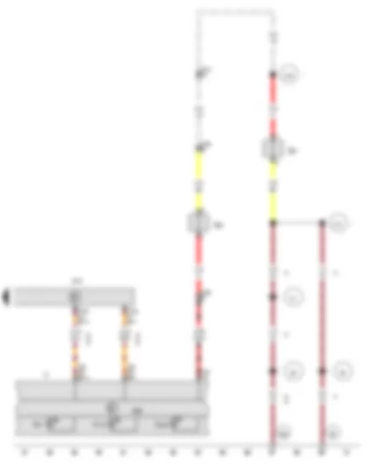
| E20 | Switch and instrument illumination regulator |
| G85 | Steering angle sender |
| J104 | ABS control unit |
| J519 | Onboard supply control unit, behind dash panel, left |
| N55 | ABS hydraulic unit |
| SC32 | Fuse 32 on fuse holder C |
| SC51 | Fuse 51 on fuse holder C |
| T6ac | 6-pin connector, black |
| T10d | 10-pin connector, blue, in E-box in engine compartment |
| T38a | 38-pin connector, black |
| T41 | 41-pin connector, grey |
| T73a | 73-pin connector, black |
| T73b | 73-pin connector, white |
| 368 | Earth connection 3, in main wiring harness |
| 636 | Earth point, onboard supply control unit |
| B277 | Positive connection 1 (15a) in main wiring harness |
| B340 | Connection 1 (58d), in main wiring harness |
| B341 | Connection 2 (58d), in main wiring harness |
| B383 | Connection 1 (powertrain CAN bus, high), in main wiring harness |
| B390 | Connection 1 (powertrain CAN bus, low), in main wiring harness |
| D159 | Connection (high bus), in engine compartment wiring harness |
| D160 | Connection (low bus), in engine compartment wiring harness |
| * | Only models with no dimmable instrument illumination |
| *2 | Only models with dimmable instrument illumination |
| G34 | Front left brake pad wear sender |
| G37 | Rear right brake pad wear sender |
| J285 | Control unit in dash panel insert |
| J519 | Onboard supply control unit, behind dash panel, left |
| K | Dash panel insert |
| K47 | ABS warning lamp |
| K118 | Brake system warning lamp |
| K155 | Warning lamp for electronic stabilisation program and TCS |
| T10j | 10-pin connector, dark brown, in E-box |
| T17f | 17-pin connector, brown, under driver seat |
| T32 | 32-pin connector, blue |
| T73a | 73-pin connector, black |
| 68 | Earth point, on left of rear cross member |
| 86 | Earth connection 1, in rear wiring harness |
| 87 | Earth connection 2, in rear wiring harness |
| 654 | Earth point, on right D-pillar |
| W31 | Connection 1 (brake pad wear indicator), in rear wiring harness |
| W32 | Connection 2 (brake pad wear indicator), in rear wiring harness |
| * | Only models with warning function for brake pad wear |
| *2 | Not for models with double cab/ dropside |
| *3 | Cross-section 6.0 possible |
| *4 | Only models with double cab/ dropside |
| *5 | Coming home with no rain sensor |
| *6 | Only models with no tachograph |
| *7 | Only models with no start/stop system |


